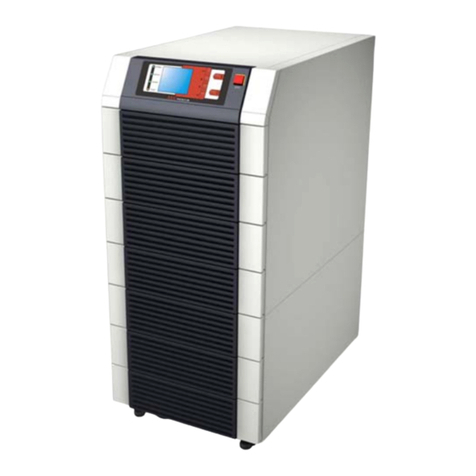
WÄRTSILÄ JOVYSTAR-DELTA User manual

Operating manual
Wärtsilä JOVYSTAR –DELTA
40 –150kVA
BAX 4647E

Wärtsilä JOVYSTAR –DELTA 40 –150kVA BAX 4647E - 2 -
Index
Date
Name
Status
1
2014-06-17
D. Busboom
First Edition
2
2014-06-25
D. Busboom
14/392
3
2017-02-20
D. Busboom
17/063
Important Notice
Read this operating manual carefully
This operating manual consists of safety-rules and rules for installation and operation as well, to help you
to maximize your benefit on this product. It has to be read carefully prior to mounting and installing this
product. It has to be placed at disposal for the installer as well as for the operator of this product.
Keep this document in a safe manner
It consists of several rules and hints for using this product, as well as also hints in cases of any questions and
problems.
Validity
Our goods and services are subject to the general delivery terms for products of the electrical industry and
our general sales conditions. We reserve the right to change the contents of information with respect to
technical data, operation, weights and dimensions. This operating instruction comprises the current tech-
nical specification of the UPS at the time of publication. The contents is informational only and do not con-
stitute a subject of contract.
WÄRTSILÄ JOVYATLAS EUROATLAS GmbH reserves the right to make any necessary changes to the
contents and technology described in this operating manual without having to make an announcement to
this effect. Wärtsilä JOVYATLAS EUROATLAS GmbH cannot be held responsible for any errors or im-
proper information in this operating manual since there is no duty upon the company to update this operat-
ing manual on an ongoing basis.
Claim
Claims are to be submitted to the vendor within eight days after delivery of this product.
Copyright
Any passing on, duplication and/or transfer by means of electronic or mechanical means, also extracts
thereof, of this operating manual, requires express prior written permission from Wärtsilä JOVYATLAS
EUROATLAS GmbH.
Copyright WÄRTSILÄ JOVYATLAS EUROATLAS GmbH. All rights reserved.

Wärtsilä JOVYSTAR –DELTA 40 –150kVA BAX 4647E - 3 -
Table Of Contents
1Technical Data 4
2General Notes 6
2.1 Description Of The System 7
2.2 Why Using A UPS? 7
2.3 General Description of A UPS 8
3Installation 12
3.1Reception 12
3.2 Transport 12
3.3 Electrical Connection 13
4Operation 17
4.1 Setting Up 17
4.2 Shut-down Procedure 17
4.3 Parallel Redundant System Start 18
4.4 Parallel Redundant System Stop 18
4.5 Manual Bypass 18
4.6 Front Panel 20
5Options 29
5.1 Temperature Compensation 29
5.2 Parallel Redundant System 29
5.3 Battery Symmetry Monitoring 30
5.4 Remote Operating Panel 31
5.5 SNMP-Adaptor 31
5.6 Relay PCB 31
5.7 Shut-down Software 32
6Maintenance and Troubleshooting 32
6.1 Maintenance 32
6.2 Visual checks 32
6.3 Functional Test 33
6.4 Inspection of Battery 33
7Troubleshooting 34
7.1 Fault Recovery 34
8Customer service 36
9Spare parts 37
10 Appendix 39
10.1 Dimensional Drawings 39
10.2 Circuit Diagrams 39
10.3 Additional Wiring Diagrams 39
Notes 40

Wärtsilä JOVYSTAR –DELTA 40 –150kVA BAX 4647E - 4 -
1 Technical Data
Wärtsilä JOVYSTAR DELTA
Online UPS-Type
40 kVA
60 kVA
80 kVA
Output
Output apparent power (cos φ= 0,8)
40 kVA
60 kVA
80 kVA
Output active power (cos φ= 1)
32 kW
48 kW
64 kW
Rated output voltage
- Tolerance static, symmetric load
- Tolerance static, asymmetric load
- Tolerance dynamic load (0 % → 100 % → 0 %)
- Correction time after load step
3 x 400/230 V
±1 %
±2 %
±8 %
< 40 ms
Rated output frequency
- Tolerance at free running quartz oscillator
- Tolerance at inverter-synchronization with mains
50/60 Hz
±0,001 Hz
±2 Hz
Rated output current (cos φ= 0,8)
58 A
87 A
116 A
Rated output current (cos φ= 1,0)
46 A
70 A
93 A
THDU (according to IEC EN 62040-3)
- Linear load
- Non linear load
< 2 %
< 10 %
Input
Input voltage
3 x 400/230 V ±10 %
Input frequency
50 or 60 Hz ±5 %
Input current (at 100 % load, without battery charging)
66 A
100 A
133 A
Input current (at 100 % load, max. battery current)
79 A
116 A
149 A
Input power factor (at 100 % load)
> 0,8
Input current THD (at 100 % load)
< 32 %
Battery
Number of battery cells
192
Compensation charging voltage
436 V (2,27 V/Z)
Cut-off voltage
326 V (1,70 V/Z)
Max. battery charging current (at 100 % load)
13 A
16 A
16 A
Battery charging characteristic
IU (DIN 41773)
Overload capability/Output short circuit characteristic
Overload capability inverter
>100 % to 125 % for 10 min
> 125 % to 150 % for 1 min
> 150 % to 199 % for 100 ms
Overload capability static bypass
150 % steady
200 % for 1 min
2000 % for 1 cycle
Short circuit current limitation
92 A
110 A
186 A
Short circuit characteristic
1. Current limitation to 200 % for 100 ms
2. Current limitation to 125 % for another 5 s
3. Shutdown of the inverter for 30 min
Design/Conformity
Dimensions (W x H x D)
690 x 1345 x 865 mm
815 x 1670 x 820 mm
Weight (without battery)
450 kg
450 kg
813 kg
Paint
RAL 5026 / RAL 9006
Noise level
< 62 dB
EMV-class according to IEC EN 62040-2
C3
Class of protection according to IEC EN 62040-3
1
International protection
IP 20
Other data
Efficiency normal mode (at 100 % load)
> 90 %
Efficiency battery mode (at 100 % load)
> 93 %
Max. crest factor without power reduction
3 : 1
Heat dissipation
(at 100 % load and rated input voltage)
3,55 kW
3,55 kW
7,11 kW
Requirements to the installation position
Max. installation altitude without power reduction
< 1000 m
Power derating for installation at altitudes higher than
1000m according to IEC EN 62040-3
1 % each 100 m > 1000 m up to max.. 5000 m
Minimum distance between UPS and wall
100 mm
Required air cooling volume
1200 m³/h
1500 m³/h
2100 m³/h
UPS operating ambient temperature
0 to +40 °C
UPS storage temperature
-10 to +70 °C
Battery ambient temperature
(recommended battery ambient temperature,
see also battery operating instruction)
0 to +25 °C
+20 °C
Battery storage temperature
0 to +25 °C
Relative humidity (non condensing)
< 95 %

Wärtsilä JOVYSTAR –DELTA 40 –150kVA BAX 4647E - 5 -
Wärtsilä JOVYSTAR DELTA
Online UPS-Type
100 kVA
125 kVA
150 kVA
Output
Output apparent power (cos φ= 0,8)
100 kVA
125 kVA
150 kVA
Output active power (cos φ= 1)
80 kW
100 kW
120 kW
Rated output voltage
- Tolerance static, symmetric load
- Tolerance static, asymmetric load
- Tolerance dynamic load (0 % → 100 % → 0 %)
- Correction time after load step
3 x 400/230 V
±1 %
±2 %
±5 %
< 40 ms
Rated output frequency
- Tolerance at free running quartz oscillator
- Tolerance at inverter-synchronization with mains
50/60 Hz
±0,001 Hz
±2 Hz
Rated output current (cos φ= 0,8)
145 A
181 A
231 A
Rated output current (cos φ= 1,0)
116 A
145 A
185 A
THDU (according to IEC EN 62040-3)
- Linear load
- Non linear load
< 2 %
< 5 %
Input
Input voltage
3 x 400/230 V ±10 %
Input frequency
50 or 60 Hz ±5 %
Input current (at 100 % load, without battery charging)
160 A
200 A
256 A
Input current (at 100 % load, max. battery current)
200 A
250 A
325 A
Input power factor (at 100 % load)
> 0,8
Input current THD (at 100 % load)
< 30 %
Battery
Number of battery cells
192
Compensation charging voltage
436 V (2,27 V/Z)
Cut-off voltage
326 V (1,70 V/Z)
Max. battery charging current (at 100 % load)
40 A
40 A
50 A
Battery charging characteristic
IU (DIN 41773)
Overload capability/Output short circuit characteristic
Overload capability inverter
>100 % to 125 % for 10 min*
> 125 % to 150 % for 1 min
> 150 % to 200 % for 100 ms
*150 kVA: >100 % to 125 % for 2 min 30 s
Overload capability static bypass
150 % steady
200 % for 1 min
Short circuit current
232 A
290 A
290 A
Short circuit characteristic
1. Current limitation to 200 % for 100 ms
2. Current limitation to 125 % for another 5 s
3. Shutdown of the inverter for 30 min
Design/Conformity
Dimensions (W x H x D)
815 x 1670 x 820 mm
Weight (without battery)
813 kg
853 kg
905 kg
Paint
RAL 5026 / RAL 9006
Noise level
< 59 dB
EMV-class according to IEC EN 62040-2
C3
Class of protection according to IEC EN 62040-3
1
International protection
IP 20
Other data
Efficiency normal mode (at 100 % load)
> 92 %
Efficiency battery mode (at 100 % load)
> 94 %
Max. crest factor without power reduction
3 : 1
Heat dissipation
(at 100 % load and rated input voltage)
6,9 kW
5934 kcal/h
8,7 kW
7482 kcal/h
11,1 kW
9546 kcal/h
Requirements to the installation position
Max. installation altitude without power reduction
< 1000 m
Power derating for installation at altitudes higher than
1000m according to IEC EN 62040-3
1 % each 100 m > 1000 m up to max.. 5000 m
Minimum distance between UPS and wall
100 mm
Required air cooling volume
2500 m³/h
2500 m³/h
3300 m³/h
UPS operating ambient temperature
0 to +40 °C
UPS storage temperature
-10 to +70 °C
Battery ambient temperature
(recommended battery ambient temperature,
see also battery operating instruction)
0 to +25 °C
+20 °C
Battery storage temperature
0 to +25 °C
Relative humidity (non condensing)
< 95 %

Wärtsilä JOVYSTAR –DELTA 40 –150kVA BAX 4647E - 6 -
2 General Notes
It is mandatory to fulfil al works and safety requirements according to rules and instructions described herein for protect-
ing the personnel working at the UPS as well as maintaining optimal duty-cycles of the UPS. All personnel installing/de-
installing, starting up, and maintaining the unit must be familiar with and observe these safety regulations. Only qualified
personnel may carry out the described work with suitable and intact tools, equipment, test equipment and materials.
Important instructions are highlighted by "CAUTION:", "ATTENTION:", "NOTE:" and indented text.
CAUTION:
This symbol identifies all working and operational procedures requiring absolute compliance to avoid
any danger to personnel.
ATTENTION:
This symbol identifies all working and operational procedures requiring absolute compliance to prevent
any damage to the UPS or some of its components.
i
NOTE:
This symbol identifies technical requirements and additional information requiring the operator's atten-
tion.

Wärtsilä JOVYSTAR –DELTA 40 –150kVA BAX 4647E - 7 -
2.1 Description Of The System
Congratulations for chosen a UPS out of the JOVYSTAR series! This type of static UPS incorporates the latest state of
technology in power electronics and digital signal processing. The UPS offers the optimal solution for problems in power
supply of computer-systems.
UPS of this series are capable to communicate with different computer operating systems through a standardized
RS232-interface. The necessary software as well as additional hardware like SNMP-Agent, MODEM etc. for remote
control of the UPS is available as an option.
JOVYSTAR UPS are real online systems (UPS-classification VFI SS 111 acc. IEC 62040-3), which prevents the at-
tached loads from mains disturbances like spikes, blackouts and voltage variations. The products are screened by an
effective quality management system. Therefore the JOVYSTAR offers a perfect solution for various power supply prob-
lems.
The reliability of the product is our major goal since over 60 years of experience in secured power supply and tech-
niques.
The scope of this manual is to describe the UPS and to guide the installer and the user through the correct installation.
The installer and the user will have to read this manual with care and attention and correctly carry-out the instructions
provided, especially those relevant to security according to the local standards and regulations.
i
NOTE:
The manufacturer declines all responsibility for damages to people or equipment deriving from non-
fulfilment of the instructions mentioned in this manual.
2.2 Why Using A UPS?
The reliable power supply is one of the major issues when installing computer-based process controlling systems. The
main reasons of all disturbances are:
- Spikes, produced by switching devices in the mains distribution
- High frequency superposition caused by welding machines, fluorescence radiation, copy machines and other,
- Voltage variations, due to load variations of big inductive consumers, such as lifts, transformers, machines
and others,
- Voltage breakdown, due to disturbances in the mains,
- Frequency variations, caused by using separate power supply units.
The range of disturbances for the attached loads begins with data errors or storing-loss and extends to hardware failure
or even production blackouts. Therefore the quality of power supply is an important factor for the reliability of electronic
data processing equipment or any other sensitive loads.
The best solution for a secure and safe power supply of critical loads is the use of an Uninterruptible Power Supply
(UPS). The UPS:
- Generates a constant voltage supply and frequency,
- Filters, respective suppresses mains disturbances down to a negligible value,
- Guarantees an uninterruptible power supply of the attached loads during a mains
failure for a specified period.
The UPS of the series JOVYSTAR is a system, is being connected between the mains and the load. It always guaran-
tees a secure power supply to the load over a specified period of time. In comparison to conventional power sources
(mains, motor aggregates, generators) the main advantages of the JOVYSTAR series are as follows:
-Optimal quality of the output voltage,
-Prevention from spikes, superposition, transient over-voltages etc.,
- Prevention from voltage variations and mains failures,

Wärtsilä JOVYSTAR –DELTA 40 –150kVA BAX 4647E - 8 -
~=~
=~
~
~
~
Netz
(USV+Bypass) Ausgang
BCB
RCB
SBCB
MBCB
Batterie
OCB
(Gleichrichter) (Wechselrichter)
(Statischer Schalter)
(Manueller Bypass)
-Prevention from frequency variations,
-Low noise,
-Small, compact design,
-Remote control facility by PC (option),
-Remote control by modem (option).
2.3 General Description of A UPS
UPS of this series are true on-line, double conversion UPS (classification-code VFI-SS-111); the inverter supplies the
load under normal operating conditions, whether mains is available or not (according to the battery autonomy time).
ATTENTION:
The UPS output is energized even during mains failure, therefore in compliance with the prescriptions of
EN 62040, the installer must label the outlets, plugs or lines supplied by the UPS, making the user aware
of this fact.
This true online concept guarantees great advantage to the user, as it supplies clean, continuously regulated power and
guarantees a stabilized voltage. Thanks to the double conversion principle, the load will be protected from micro-
interruptions due to excessive mains variation. It prevents damage to the critical load.
Block diagram
Legend of the block diagram:
- Input UPS Input terminals (1L1, 1L2, 1L3, PE.)
- Input Bypass Bypass input terminals (2L1, 2L2, 2L3, 2N, PE.)
- RCB Rectifier Circuit Breaker
- SBCB Static Bypass Circuit Breaker
- MBCB Manual Bypass Circuit Breaker
- BCB Battery Circuit Breaker or battery fuses. In case of an external battery terminals
+B and –B will be provided instead of the internal BCB, as well as an external bat-
tery circuit breaker
- OCB Output Circuit Breaker
- UPS Output Output terminals (3L1, 3L2, 3L3, 3N, PE.)
(Manual bypass)
(Inverter)
(Rectifier)
(Static switch)
Battery
Mains
(UPS+Bypass)
Output

Wärtsilä JOVYSTAR –DELTA 40 –150kVA BAX 4647E - 9 -
- Rectifier The rectifier converts the input AC-voltage into a regulated DC-voltage supplying the
inverter and charging the batteries.
- Inverter The inverter converts the DC-voltage delivered by the rectifier or by the battery into
an AC-voltage, regulated by Pulse-Width-Modulation. The output of the inverter is
short circuit proof by electronic short-circuit-protection.
With an output current> 100% of rated current or a failure of the inverter the power
supply is switched without interruption on the bypass through the internal static
switch.
- Static Switch The static bypass consists of a thyristor-switch. It switches the mains over to the
UPS output. During normal operation the inverter output is switched to the UPS out-
put while the bypass is blocked. During overload at the UPS output or an inverter
failure the attached loads will be supplied immediately by the bypass.
- Manual Bypass The manual bypass feeds the load in case of maintenance or disturbances of the
UPS. The manual bypass is to be used only by qualified personnel under considera-
tion of the described instructions in this manual!
ATTENTION:
A handling error of the internal or (if applicable) any external manual bypass could lead
to a total blackout at the output of the UPS!
2.3.1 Rectifier
The rectifier converts the three phase voltage of the mains into a DC voltage. It uses a 6 pulse fully-controlled thyristors
bridge. The rectifier is designed to supply both the inverter at full load and the battery at the maximum recharge current.
The system offers very low ripple content during the charging cycle.
2.3.1.1 Twelve-Pulse Rectifier (Option)
The twelve-pulse technology is used to reduce the distortion of the current absorbed from the mains (THD) to a value
<12%. This ensures that the rectifier does not distort the mains above these limits. A higher distortion could be an issue
for other loads. It also avoids overloading of cables due to the harmonics circulation. This system is highly recommend-
ed for high power equipment, where the current distortion caused by the rectifier might affect other loads connected to
the mains.
The twelve-pulse rectifier can be provided both, with or without galvanic isolation. It is built by either a choke together
with an isolating transformer or by a transformer with two secondary windings.
twelve-pulse rectifier without galvanic isolation twelve-pulse rectifier with galvanic isolation
2.3.2 Inverter
It converts the DC-voltage delivered by the rectifier or battery into alternating, stabilized voltage. The control circuitry is
completely digitally. Due to the fast regulation it generates an excellent output sine-wave, which has a very low distortion
even in presence of loads having high crest factor currents.
RCB
Inverter
Battery
Mains
Rectifier
Master
Rectifier
Slave
RCB
Inverter
Battery
Mains
Rectifier
Master
Rectifier
Slave

Wärtsilä JOVYSTAR –DELTA 40 –150kVA BAX 4647E - 10 -
~=~
=~
~
~
~
Ausgang
BCB
RCB
SBCB
MBCB
Batterie
OCB
(Gleichrichter) (Wechselrichter)
(Statischer Schalter)
(Manueller Bypass)
Netz
(USV+Bypass)
~=~
=~
~
~
~
Ausgang
BCB
RCB
SBCB
MBCB
Batterie
OCB
(Gleichrichter) (Wechselrichter)
(Statischer Schalter)
(Manueller Bypass)
Netz
(USV+Bypass)
2.3.3 Battery and Battery Charger
The battery is placed inside the UPS up to 32KVA in case of small autonomy times. It is placed in an external battery
cabinet for higher UPS ratings and/or autonomy times. The control-electronic for the rectifier includes the circuits for the
battery charger too. The battery operates in stand-by parallel operation to the rectifier. For obtaining the maximum life-
time of the battery it is charged in trickle-mode according to DIN 41773.
2.3.4 Static Bypass
It serves to transfer the load between INVERTER and MAINS, and vice-versa, without interruption, and uses SCR’s as
power commutation elements.
2.3.5 Manual Bypass
It provides a solution of bypassing the UPS by itself, supplying the load directly by the mains in case of maintenance or
serious failure.
ATTENTION:
The sequence of switching to bypass must be carried out with respect to the procedure
indicated on the UPS and in the chapter “Operating the UPS”. The manufacturer cannot
accept responsibility for damages arising from incorrect operation.
2.3.6 Front Panel
The front panel of the UPS, consists of a double row alphanumeric display including 5 function keys, allows the com-
plete monitoring of the UPS status. The mimic diagram helps to understand the operating status of the UPS. For more
information see the chapter “Operation”.
2.3.7 Operating Status
2.3.7.1 Normal Operation
The inverter is supplied by the rectifier. The load is supplied directly by the inverter via the static switch.
Normal operation
2.3.7.2 Inverter Fault
The load is transferred to bypass through the static switch; the transfer is carried out without interruption.
Load supplied by bypass
(Manual bypass)
(Inverter)
(Rectifier)
(Static switch)
Battery
Mains
(UPS+Bypass)
Output
(Manual bypass)
(Inverter)
(Rectifier)
(Static switch)
Battery
Mains
(UPS+Bypass)
Output

Wärtsilä JOVYSTAR –DELTA 40 –150kVA BAX 4647E - 11 -
~=~
=~
~
~
~
Ausgang
BCB
RCB
SBCB
MBCB
Batterie
OCB
(Gleichrichter) (Wechselrichter)
(Statischer Schalter)
(Manueller Bypass)
Netz
(USV+Bypass)
~=~
=~
~
~
~
Ausgang
BCB
RCB
SBCB
MBCB
Batterie
OCB
(Gleichrichter) (Wechselrichter)
(Statischer Schalter)
(Manueller Bypass)
Netz
(USV+Bypass)
2.3.7.3 Rectifier- Or Mains Failure
The inverter is supplied by the battery for the autonomy time specified by the battery. The load is supplied directly by the
inverter via the static switch.
Rectifier- or mains failure
2.3.7.4 Manual Bypass
The load is supplied by the mains through the manual bypass. Maintenance or repair can be carried out safely on the
UPS.
Manual bypass
(Manual bypass)
(Inverter)
(Rectifier)
(Static switch)
Battery
Mains
(UPS+Bypass)
Output
(Manual bypass)
(Inverter)
(Rectifier)
(Static switch)
Battery
Mains
(UPS+Bypass)
Output

Wärtsilä JOVYSTAR –DELTA 40 –150kVA BAX 4647E - 12 -
3 Installation
3.1 Reception
After reception of the UPS, unpack immediately and carry-out an accurate visual check for any transport-damages.
i
IMPORTANT:
In case of objections relating to damage incurred during transport these must be immediately notified to
the transportation company after reception of the product.
When the UPS is not installed immediately it must be stored carefully in vertical position, as indicated on
the packing and conserved in a dry and sheltered room in its box so that it is protected from dust.
3.2 Transport
Before positioning the UPS, in order to avoid risks of turnover, it is recommended to move the system only while mount-
ed on the wood pallet. Before the positioning in the final location, remove the pallet from the UPS. The UPS can be lifted
and handled using a pallet truck or a forklift.
3.2.1 Setting Up and Installation
The UPS must be installed in a clean and dry room, preferably not dusty. The user must ensure a proper air conditioning
for cooling the equipment. If the UPS contains the batteries internally the air exchange with the external ambient must
comply with EN 62040, annex N.
3.2.2 Ground Plan
Ground Plan
Designation
40-60kVA |80-150kVA
L1 - mm
660 | 775
P1 - mm
825| 750
L2 - mm
50 | 100
L2
P1
L1

Wärtsilä JOVYSTAR –DELTA 40 –150kVA BAX 4647E - 13 -
3.2.3 Dimensions And Wall System Distance
Dimensions and wall system distance
Designation
40-60kVA | 80-150kVA
L –mm
690 | 815
P –mm
865 | 825
H –mm
1340 | 1670
X (min.) –mm
50 | 50
Y (min.) –mm
500 | 500
Additional cabinet
Twelve-pulse rectifier (option)
L1 –mm
690 | 815
3.3 Electrical Connection
ATTENTION:
Even with switched off mains there is a dangerous high battery voltage inside the UPS. All installations
and connections may only be carried out by qualified technicians. The technician must familiarize himself
with the special features of this UPS by carefully reading and understanding this manual.
Please observe the special notices for connections of a parallel-system.
The work for electrical connection is a part of an electrician who installs the whole electric installation. It is not part of the
UPS manufacturer. For this reason, the following recommendations are only an indication, as the UPS manufacturer is
not responsible for the electrical installation.
In any case we recommend carrying out the installation and the electrical connections to the UPS in accordance to the
local rules and standards.
During the electrical installation make sure a right phase rotation at the three-phase input terminals of the UPS.
In case of strong electromagnetic fields emission it is recommended to use a shielded cable between UPS and the load.
In accordance to EN 62040-1 a mains-feed-back protection has to be provided for the UPS, preventing a current flow
from the output of the UPS back into mains at a single fault of the system. Therefore both the lines for the main input
and the bypass lines have to be fed via a contactor, which opens in case of a mains blackout.
For improving the quality of connection of the UPS flexible cables are recommended. A cable clamp must be provided
by the end-user directly at the structure of the frame or right below the UPS cabinet.
The wire diameters given in technical data refer to a distance of 50m between load and UPS. These values are recom-
mendations only. They have to be recalculated particularly considering the actual environment conditions!
At larger distances the permissible voltage drop, the environmental temperature and the cable grounding have to be
dimensioned according to VDE or local rules. Local rules for the protection ground-wires have to be considered.
The suitable diameters of cables and the sizes of the fuses are to be designed with regard to the environmental temper-
ature, the cable grouping and length of cables according to the local rules and according to VDE.
The terminals are positioned at the lower part of the UPS and they can be accessed by opening the front door.
H
P
L1
X
Y
Additional cabinet
(12 pulse rectifier)
L
UPS
UPS
Additional cabinet
(12 pulse rectifier)
H
P
L1
X
Y
Additional cabinet
(12 pulse rectifier)
L
UPS
UPS
Additional cabinet
(12 pulse rectifier)

Wärtsilä JOVYSTAR –DELTA 40 –150kVA BAX 4647E - 14 -
ATTENTION:
The input lines to the UPS must be fuse protected. The use of residual current switches in the line sup-
plying the UPS is not recommended. The leakage current due to the RFI filters is rather high and it can
cause spurious tripping of the protection device.
If any residual-current-switch has to be used, it is recommended the use of a device with short-time
delay for differential currents higher than 300mA.
The following table represents a summary about the current carrying capacity acc. DIN VDE- and EN-rules at an envi-
ronmental temperature of 30°C.
The necessary diameters of cable and the sizes of the fuses are to be designed with regard to the environmental tem-
perature, the cable grouping and length of cables according to the local rules and according to VDE.
The given values of cable diameters do not reflect the required diameters of the protective earth cable! They have to be
calculated in accordance to VDE 0100 part 540 or an applicable local rule.
Designation
40 kVA | 60 kVA | 80kVA | 100kVA | 125kVA | 150kVA
Input fuses [AgL]
Rectifier
3 x 80 | 3 x 125 | 3 x 160 | 3 x 200 | 3 x 250 | 3 x 315
Bypass
| 3 x 160 | 3 x 200 | 3 x 315
Input cables (mm²)
Rectifier
4 x 35 | 4 x 70 | 4 x 95 | 4 x 120 | 4 x 120 | 4 x 150
Bypass
| 4 x 95 | 4 x 120 | 4 x 150
Output cables (mm²)
4 x 25 | 4 x 50 | 4 x 70 | 4 x 95 | 4 x 120 | 4 x 150
Battery cables (mm²)
2 x 70 | 2 x 95 | 2 x 120 | 2 x 150 | 2 x 150 | 2 x 240
External battery cabinet, required fuses [AgL]*)
2 x 125 | 2 x 160 | 2 x 250 | 2 x 320 | 2 x 320 | 2 x 400
*) Note: Suitable for DC-current applications
3.3.1 Terminal Board
WARNING:
The UPS requires the neutral of the bypass input only. When using the neutral of the main input too,
both neutrals have to be connected together.
40-60 KVA (Bars with mounting hole)
Note.: L1-L3 and N = Hole for screw M8. PE Terminal: Bolt M10
ATTENTION:
For ensuring the selectivity all fuses should have the utilization category “gL”. In this case selectivity is
existent for fuses up to 16AgL. When using higher fuse ratings or automatic cutout a selectivity calcula-
tion must be carried out according to the local requirements. For the battery fuses a suitable breaking
capability must be ensured.
1-L1 1-L2 1-L3
EINGANG
GLEICHRICHTER
3-L1 3-L2 3-L3
AUSGANG
3-N +B -B
BATTERIE
2-L1 2-L2 2-L3
EINGANG BYPASS
2-N
Bac1
Bac2
SICHERUNGS-
ÜBERWACHUNG
(OPTION)
1-L2
1-L1
1-L3
1-N
Input Bypass
+ Rectifier
Output
Battery
Fuse monitoring
(option)

Wärtsilä JOVYSTAR –DELTA 40 –150kVA BAX 4647E - 15 -
80-150 kVA (Bars with mounting hole)
Note.: L1-L3 and N = Hole for screw M10. PE Terminal: Bolt M10
3.3.2 External Battery
i
IMPORTANT:
Prior to connecting to any external battery the standard EN62040, par. 4.5 must be observed. For ensur-
ing the maximum lifetime for the battery, according to the statements of the battery manufacturer, the
operating temperature of the battery must be held between 20°C and 25°C. Otherwise the lifetime will be
reduced drastically, even in the case that the battery can work at temperatures of up to 40°C. For pre-
venting of forming explosive gases of hydrogen/oxygen mixtures a suitable air-ventilation has to be
installed according to EN62040, Annex N).
It is recommended install the battery, either internal or external, only if the UPS will be able to recharge it. Consider that
a battery which is not being charged within 2-3 months can be irreversibly damaged.
i
IMPORTANT:
A battery must be maintained periodically. Observe the instruction manual of the battery manufacturer. It
will be found in the annex of this manual.
WARNING:
After switching off the UPS, please remove the Battery Fuses. In other case, the power supply consume
a little current from the Battery. After a couple of hour, the battery is damaged.
Please contact our Service department after a failure. Jovyatlas does not take over any liability for late
error reports.
3.3.2.1 Connections External Battery Cabinets
Depending on the autonomy time, the external battery will be mounted in different cabinets.
Type of battery cabinet
B10E
B11E
B12
B13
Dimensions Width [mm]
Height [mm]
Depth [mm]
511
1200
790
511
1340
790
910
1620
810
910
1820
810
Weight of cabinet without batteries [kg]
70
80
125
140
Protection degree
IP 20 according to DIN 40050
Protection class
1 according to VDE 0106 / part 1
For information about the connection of a row of battery cabinets please refer to the circuit diagram Y8901000.SP3 in
annex.
1-L1 1-L2 1-L3
Rectifier input
3-L1 3-L2 3-L3
Output
3-N +B -B
Battery
2-L1 2-L2 2-L3
Bypass input
2-N
Bac1
Fuse monitoring
(option)
Bac2

Wärtsilä JOVYSTAR –DELTA 40 –150kVA BAX 4647E - 16 -
3.3.2.2 Battery Connection in Internal Battery Shelf
Battery connection in internal battery shelf
BOTTOM
BATTERY DRAWER NO.
TOP
TO BCB
REAR
FRONT
+
-
+
-
+
-
+
-
-B
+
+
-
+
-
-
+
+
-
+
-
-
+
+
-
+
-
-
+
+
-
+
-
-
+B
1 2 3 4 5
- - - -
+ + + +
+
+
-
+
-
-
+
+
-
+
-
-
+
+
-
+
-
-
6 7 8
- - -
+ + +

Wärtsilä JOVYSTAR –DELTA 40 –150kVA BAX 4647E - 17 -
4 Operation
Prior to carrying out whatever procedure described in this chapter, read carefully the instructions, in order to avoid pos-
sible damages to persons or the UPS due to wrong maneuvers.
4.1 Setting Up
i
NOTE:
The battery circuit breaker BCB may be switched only when the rectifier is running. Otherwise the rectifier
could be damaged. This is also true for inserting battery fuses! The BCB is installed inside the UPS. When
using a UPS with an external battery a fuse circuit breaker will be mounted externally instead of BCB.
Procedure:
Close RCB and wait until display is coming up. Follow the instructions shown on the display to close the circuit breaker /
isolator switches as indicated. If the start-up procedure has been carried out correctly, the display will show:
4.2 Shut-down Procedure
For the UPS shut-down, proceed as follow.
1. Open OCB
2. Open BCB
3. Open SBCB
4. Open RCB
INV START UP
WAIT PLEASE
START UP
WAIT PLEASE
BYP START UP
CLOSE SBCB
BATTERY START UP
CLOSE BCB
START UP END
CLOSE OCB
START UP END
WAIT PLEASE
Remark (not displayed):
Close also external battery fuses!
JOVY-M XXX KVA
XXX ZZZ YYY KVA
BATTERY START UP
WAIT PLEASE
BYP START UP
WAIT PLEASE

Wärtsilä JOVYSTAR –DELTA 40 –150kVA BAX 4647E - 18 -
CAUTION:
Even at switched off input mains, a dangerous high voltage is still present inside the UPS!
CAUTION:
The circuit breaker in the external battery cabinet may only be operated without current flow. Observe
the switch off procedure! The load on the output of the UPS has to be switched off prior to operating the
battery circuit breaker.
4.3 Parallel Redundant System Start
At commissioning of UPS units in parallel-redundant operation the SLAVE-UPS(s) have to be started first exactly in the
same manner it is described for a single unit. The last UPS to be started is the master-UPS.
4.4 Parallel Redundant System Stop
All instructions also apply for parallel-redundant operation.
4.5 Manual Bypass
ATTENTION:
Switching the MBCB in a wrong sequence could lead to a blackout for the loads. The use of the
manual bypass is only designated for qualified personnel. Please consult our service department or your
dealer before using the manual bypass!
4.5.1 Manual Bypass (Single System) Initiation
ATTENTION:
We strongly point out that the load is not supplied with a secure power-supply when using either the inter-
nal or an external bypass. A mains blackout could lead to an interruption of the power-supply to the load.
For initiating the manual bypass the UPS must be synchronized to the mains. This is accomplished it the status mes-
sage S5 is active!
- Switch over the service switch (near the RS 232 interface) from “Normal” into “Bypass” position.
- Now following alarms will appear on the display:
A16 BYP feeds load
A22 BYP switch
- Confirm these alarms by pressing the buzzer key on the operating panel.
i
NOTE:
Proceed only if no other alarm message appears!
- Close the MBCB in the UPS.
- Close the external manual bypass, if available.
- Following alarms will be appear on the display:
A13 INV OUT TOL (inverter out of tolerance)
A18 MBYP closed (manual bypass closed)
- Confirm these alarms by pressing the buzzer key again.
- Open OCB. Now the load is disconnected from the UPS system.
- Open BCB.
- Open SBCB.
- Open RCB

Wärtsilä JOVYSTAR –DELTA 40 –150kVA BAX 4647E - 19 -
CAUTION:
Even at switched off input mains, a dangerous high voltage is still present inside the UPS!
i
NOTE:
The load is powered now by the mains. Any blackout in the mains will lead to a blackout for the loads.
4.5.2 Manual Bypass (Parallel Redundant Operation) Initiation
The procedure must be carried out at every UPS unit:
- Set the service switch into Bypass position, wait and acknowledge the alarm as described for a single UPS
- Close MBCB, wait and acknowledge the alarms as described for a single UPS operation
- Open OCB.
- Open BCB.
- Open SBCB.
- Open RCB
4.5.3 Manual Bypass (Single system) Switch Off
Conditions:
- The UPS system is switched off, the manual bypass MBCB is active.
- The service switch is set in bypass position.
Procedure:
- Close the RCB.
- Close the SBCB.
- Close the BCB (also external battery fuses).
- Close the OCB.
- Open the external manual bypass, if available.
- Open the MBCB.
- Switch over the service switch from “Bypass” to “Normal” position.
4.5.4 Manual Bypass (Parallel Redundant Operation) Switch Off
Conditions:
- The UPS system is already switched off, the manual bypass MBCB is active.
- The service switch is set in bypass position.
Procedure:
… in SLAVE-UPS: - Close the RCB.
after request on the display - Close the SBCB.
after request on the display - Close the BCB.
after request on the display - Close the OCB.
… in both UPS
after request on the display - Open MBCB.
after request on the display - Service switch on “Normal” position.
…(in MASTER-UPS) -Close the RCB.
after request on the display - Close the SBCB.
after request on the display - Close the BCB.
after request on the display - Close the OCB.

Wärtsilä JOVYSTAR –DELTA 40 –150kVA BAX 4647E - 20 -
4.6 Front Panel
The front panel of a UPS consists of a double row alphanumeric display plus 5 function keys. It allows the complete
monitoring of the UPS status. The mimic flow helps to understand the operating status of the UPS.
4.6.1 Front Panel LED
LED 1
Lit-up green
Mains present at the rectifier input.
Otherwise off.
LED 2
Lit-up green
Emergency line (bypass-line) present and phase sequence correct.
Otherwise off.
LED 3
Lit-up green
Rectifier feeding correctly.
Lit-up red
Rectifier output voltage out of tolerance.
LED 4
Lit-up green
Battery OK.
Green flashing
Battery discharging or battery in test.
Orange flashing
BCB open.
Lit-up red
Battery test aborted.
LED 5
Lit-up green
Inverter static switch closed.
Otherwise off.
LED 6
Lit-up orange
Emergency line static switch closed.
Otherwise off.
LED 7
Lit-up green
Voltage present on the load.
Lit-up orange
OCB circuit breaker open.
LED 8
Lit-up orange
Manual bypass closed.
Otherwise off.
LED 9
Lit-up red
EPO push-button pressed
~=~
=
~
~
EPO
RESET
JOVYATLAS
1
2
3
8
47
5
6
9
This manual suits for next models
1
Table of contents
Other WÄRTSILÄ UPS manuals

WÄRTSILÄ
WÄRTSILÄ JOVYATLAS POWERMASTER S 6000-P User manual

WÄRTSILÄ
WÄRTSILÄ JOVYCUBE 160 User manual

WÄRTSILÄ
WÄRTSILÄ JOVYSTAR HP 200 kVA User manual

WÄRTSILÄ
WÄRTSILÄ JOVYTEC L Series User manual

WÄRTSILÄ
WÄRTSILÄ JOVYTEC P Series User manual

WÄRTSILÄ
WÄRTSILÄ JOVYTEC PMS 2002K User manual

WÄRTSILÄ
WÄRTSILÄ JOVYTEC POWERMASTER PMS 6000 User manual

WÄRTSILÄ
WÄRTSILÄ JOVYREC D600 G120/10 User manual

WÄRTSILÄ
WÄRTSILÄ JOVYSTAR COMPACT S BAX 5452 User manual