WA Library Supplies EG866 User manual

EG866 Instruction Manual
A.
Technical Specifications
Operating voltage : 2 x AA t pe batter or 3.3VDC A/C power suppl
Operating current : Transmitter 750µA
Receiver 750µA
Net weight : Transmitter 90g (inclusive of batter )
Receiver 95g (inclusive of batter )
Dimensions : 68 x 42 x 22 mm per unit
Detection distance : 1m to 8m
Maximum digital count : 999,999
Operating mode : Infrared sensors with remote wireless (433MHz)
connection to computer via USB.
Batter life : not less than 4 months (continuous operation)
Installation : front or side facing
B.
Features
Transmitter (Tx) Receiver (Rx)
1. Infrared sensor, front facing
2. Infrared sensor, side facing
3. On/off switch
4. elector for infrared sensor, left for side and right for front
5. Power LED indicator, when on, flashes once every 4 seconds
6. LCD screen, numerical display
As EG866 uses infra-red sensors, if counter is positioned behind glass doors, there could be
error counts due to reflections. If glass doors are opened one way, it would be best to affix the
counters in the other side to avoid error counts due to reflection.
1
2
3
4
5 6

C.
Operation
1. Fix base plate on either side of the wall or door.(see photo 1)
Photo 1(a): secure base plate to Photo 1(b) Insert EG866 from the Middle, Push inward
fixture by screws, tape or glue. and Slide Up as per Arrow and click to position.
2. Ensure the position of the two base plates on either side are in exactly the same height and
direction so that the Infrared beam can be transmitted and received freely (see photo 2).
Photo 2
3. There are two sensors in each EG866 (front and side), use the selector at the base of the unit to
identify front or side infrared sensors to be used.
4. Transmitter - press and hold button for 2 seconds, Power Indicator (red light) on unit will lit up
for 5 seconds, then flashes once every 4 seconds thereafter. Press and hold button for 2
seconds again, the red light will flash 3 times and the unit will turn off.
5. Receiver - press and hold button for 2 seconds, the LCD screen will turn on. Press and hold
button for 2 seconds again, LCD screen will turn off. If press button in 2 quick successions, the
digital display will return to zero.
6. When power up, the LCB screen will flash with “- - - - - -“ (see photo 3)while it tries to obtain a
code from the transmitter. This may take a few seconds. Once the units are aligned correctly
and codes verified, the LCD screen will show “000000” (see photo 4).
Photo 1(c) To remove, press the
two tabs on either side of the
base plate and slide the EG866
downward.
Tab
Arrow

Photo 3 Photo 4 Photo 5
7. If position is incorrect i.e. the receiver and transmitter not lined up correctly, LCD screen will
show Error (see photo 5). Check front/side sensors are correctly selected and align in position.
8. The units can be connected wirelessly to computer via U B receiver/cable for data analysis
using eGuard’s self proprietary mart Management ystem. Please refer to separate software
manual for details.
U B receiver/cable
9. The transmission from receiver to computer will take place automaticall ever 3 minutes. It
can also be transmitted manuall b pressing the on/off switch in the transmitter once. The
counts will be transmitted right awa . To reset the counter to zero, simpl press the on/off
switch in the receiver in two quick successions.
10. The units can also be connected to power supply (optional and not included in the package). If
power supply is used, the battery will act as back up and come into action when A/C power is
off.

D.
Troubleshooting
i, If LCD screen does not show 000000, check the follows:-
The counter is not placed beyond 6m
The front and side sensors are selected correctly, check selector at base of Tx and Rx
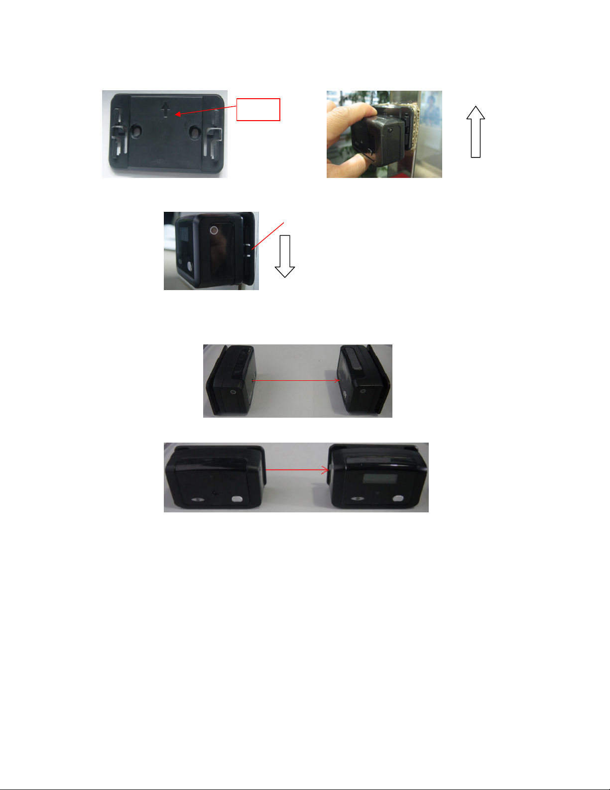
The sensors are align properly in the correct facing and height
ii, After operating normally for a period of time, no transmission between counters:-
Check that there is sufficient battery power, in normal condition the red LED in Tx will flash
every 4 seconds and the LED screen on Rx will only have numbers. If low battery, the LED
on Rx will have a replacement battery sign. The same sign will also show in the “Count”
page in the software.
Check that there has been no damage to the infra-red sensors. Bring the units closer
together to see if operation returns normal. If not, one of the sensor malfunctions and can
identify the damaged sensors by testing with side and front sensors on both units. If
situation allows, reposition the counters with the pair of good sensors.
Check that there is no strong infra red signal in the surrounding area for example alarm
sensors which may overwhelm the signals of the counters.
Iii, Data from counter not received at computer
Check that the light in the front page of the software “COM” and “Counter” are green as an
indication that the connections are in good order. The LED on U B receiver should also
show green.
Every time the on/off switch in Tx is pressed, the latest reading will be transmitted to the
computer. The LED on the U B receiver will change from green to a flash of red then green
again as a sign of receiving reading. The updated count and time will show on the “Count”
page in the software.
If no signal is received, check that the device is within 10m and there are no major
obstacles between counters and U B. Check also for possible interference from other
device using 434MHz.
To enhance transmission in noisy environment or over long distance, it may be necessary to
add one or more 15902TB, receiver booster, to enhance operation. 15902TB should be
placed near the ceiling and as close to Rx (counter with LED screen) as possible.
Table of contents