manuals.online logo
Brands
  1. Home
  2. •
  3. Brands
  4. •
  5. WABCO
  6. •
  7. Radar
  8. •
  9. WABCO OnGuard User manual

WABCO OnGuard User manual

Installation Guide
OnGuard®System Retrofit Kit
Installation Instructions
TP1368
Revised 05.2020
Safety Information
Provisions for a safe work environment:
• Only trained and qualified technicians may carry out
work on the vehicles.
• Read this publication carefully.
• Follow all warnings, notices and instructions to avoid
personal injury and property damage.
• Always abide by the vehicle manufacturer's
specifications and instructions.
• Observe all accident regulations of the respective
company as well as regional and national regulations.
• The workplace should be dry, sufficiently lit and
ventilated.
• Use personal protective equipment if required (safety
shoes, protective goggles, respiratory protection and ear
protectors).
Read and observe all Danger, Warning and Caution hazard
alert messages in this publication. They provide information
that can help prevent serious personal injury, damage to
components, or both.
WARNING
To prevent serious eye injury, always wear safe eye protection
when you preform vehicle maintenance or service.
WARNING
Park the vehicle on a level surface. Block the wheels to prevent
the vehicle from moving. Support the vehicle with safety stands.
Do not work under a vehicle supported only by jacks. Jacks
can slip or fall over. Serious personal injury and damage to
components can result.
WARNING
This product can expose you to chemicals including Nickel,
which is known to the State of California to cause cancer and
birth defects or other reproductive harm. For more information,
go to www.P65Warnings.ca.gov.
WARNING
Release all air from the air systems before you remove any
components. Pressurized air can cause serious personal
injury. Refer to the vehicle manufacturer’s service manual for
instructions.
WARNING
Verify and diagnose all active faults in the system prior to
replacing OnGuard®components. When diagnosing OnGuard®,
TOOLBOX™ Software (11.0 or higher) must be used. Be aware
that diagnostic devices must be connected prior to keying on the
unit to minimize possible OnGuard®faults during diagnosis.
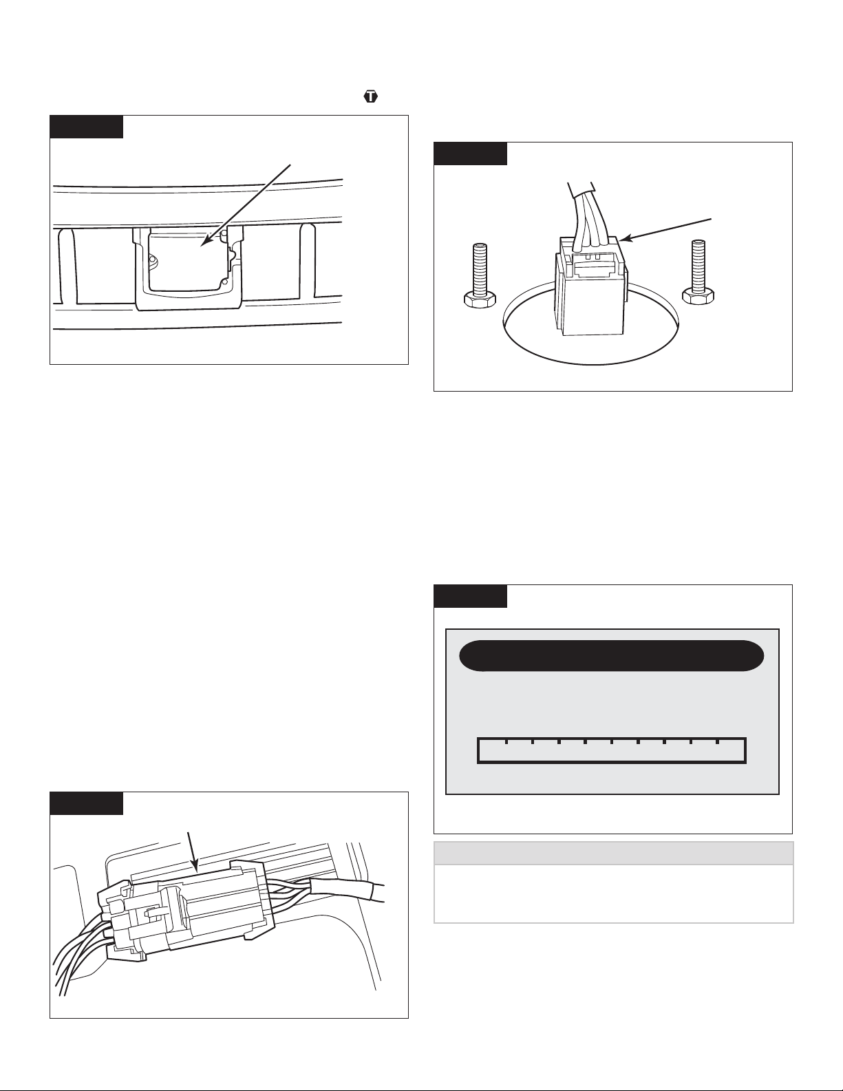
This symbol alerts you to tighten fasteners to a specific
torque value.
How to Obtain Additional Maintenance,
Service and Product Information
Refer to Maintenance Manual MM1306, OnGuard® Collision
Mitigation System. To access and download this publication
along with additional information, visit our Literature Center
at
www.wabco-na.com/literature
If you have any questions about the material covered in this
publications, or for more information about the
WABCO product line, please contact WABCO
Customer Care Center at 855-228-3203, by email at
[email protected], or visit our website:
www.wabco-na.com
How to Obtain Tools, Kits and Supplies
To obtain parts, call WABCO Customer Care Center at
855-228-3203.
TP1368 / Revised 05.2020
Page 2
OnGuard®Collision Mitigation System
(CMS) Kit
This technical bulletin provides procedures for removing
existing OnGuard®parts and installing parts included in the
OnGuard®Collision Mitigation System kit.
The following parts are included in the kit.
• Radar Sensor
• OnGuard Display
• Fascia
• Radar Adapter Harness
• Display Adapter Harness
• Radar Bracket
• Bracket Mounting Bolts
• Fascia M6 Bolts
• Radar M6 Nuts
NOTE
Care should be taken to verify the correct kit part number is
being installed on the vehicle as all CMS radars look alike.
Radar Sensor Assembly and Mounting
Bracket Removal
1. Wear safe eye protection. Park the vehicle on a level
surface. Apply the parking brake. Ensure that the
ignition is turned OFF.
2. Blocks the rear tires to prevent the vehicle from moving.
3. Remove the bumper and accessories from the front of
the tractor to gain clear access to the radar and bracket.
Refer to the vehicle manufacturer’s recommended
procedures for removal of the bumper and accessories.
4. Remove the two fascia mounting bolts and remove the
fascia from the radar sensor. Figure 1.
Figure 1
4010727a
FASCIA
MOUNTING
BOLTS
5. Disconnect the radar sensor connector by depressing
the lock tabs on both sides of the radar connector. It
is not necessary to remove the radar sensor from the
bracket. Push the cable clip out from the hole at the
corner of the bracket.
6. Remove the two 1/2-inch mounting bolts from the radar
sensor bracket and remove the bracket. Figure 2.
Figure 2
4010728a
RADAR
SENSOR
MOUNTING
BOLTS
Radar Bracket Installation
NOTE
Care should be taken to verify the correct kit part number is
being installed on the vehicle as all CMS radars look alike.
1. Verify the mounting position of the radar sensor on
the bracket. Figure 3 shows which holes are used for
mounting the radar unit depending on what type of
bumper is on the vehicle.
(PLASTIC BUMPER ONLY or STEEL BUMPER ONLY).
Figure 3.
Figure 3
4010729a
TP1368 / Revised 05.2020
Page 3
2. Place the radar in position on the bracket. Install the M6
flange nuts provided in the kit and tighten to 61-75 in-
lb (6.9-8.4 N∙m). No movement should occur between
the bracket and the radar sensor after the sensor has
been correctly installed on the mounting bracket. Figure
4.
Figure 4
4010730a
RADAR SENSOR BRACKET
3. Place the new radar sensor and bracket onto the tractor
in the same position as the old bracket and radar
sensor. Make sure the radar sensor and bracket are
mounted with the radar sensor facing outward toward
the front of the vehicle. Install the two 1/2” mounting
bolts provided in the kit and dry tighten to 100 ft-lb
(135 N∙m). Figure 5.
Figure 5
4010731a
Install the 2 mounting bolts
included in the kit.
4. Install the radar adapter harness to the vehicle OEM
radar connector by pushing on the adapter end until it
snaps into the connector. Slide the rubber boot over the
connector. Figure 6.
Figure 6
4010732a
RADAR ADAPTER HARNESS
5. Reconnect the other end of the radar adapter harness
to the new radar unit by pushing on the adapter
connector until it snaps into the radar sensor. Slide the
rubber boot over the connector until the connector is
completely covered by the boot. If required, secure the
harness using a snap clip or tie strap in the hole on the
bracket. Make sure the harness is equipped with a drip
loop and does not rub against any sharp edges. Figure
7.
Figure 7
4010733a
RADAR
SENSOR
CONNECTOR
6. Install the bumper according to the vehicle
manufacturer’s recommended procedure.
7. Verify that there is at least 1/4-inch gap (6.35 mm)
on all four sides of the radar fascia and the bumper.
If there is not a 1/4-inch (6.35 mm) gap, contact the
manufacturer for assistance in adjusting the bumper.
This gap is critical to the correct operation of the
OnGuard Collision Mitigation System.
TP1368 / Revised 05.2020
Page 4
8. Place the fascia in position over the radar sensor. Install
the M6 x 35 mm flange-head bolts included in the kit
and dry tighten to 91 in-lb (10.3 N∙m). Figure 8.
Figure 8
4010734a
FASCIA
OnGuard®Display Removal
1. Verify the ignition switch is in the OFF position.
2. In order to access the OnGuard display mounting
screws, you must remove the instrument panel
according to the vehicle manufacturer’s recommended
procedure.
3. Once the instrument panel is removed, unscrew and
remove the OnGuard display screws, nuts and washers
from the back of the panel. Save the nuts and washers
for reuse during installation of the new display.
4. Disconnect the wiring connector from the OnGuard
display.
5. Remove the OnGuard display from the instrument panel.
OnGuard®Display Installation
1. Connect the OEM display connector to the display
adapter harness by pushing on the connector end until
it snaps into the connector. Figure 9.
Figure 9
4010735a
DISPLAY ADAPTER HARNESS
2. Install the new OnGuard display using the nuts and
washers from previous display.
3. Connect the display adapter harness to the new
OnGuard display. Figure 10.
Figure 10
4010736a
DISPLAY
ADAPTER
HARNESS
4. Reinstall the instrument panel according to the vehicle
manufacturer’s recommended procedure.
5. Turn the ignition to the ON position and perform the
Radar Sensor Service Alignment procedure in this
bulletin.
Radar Sensor Service Alignment
The Radar Not Aligned screen will be displayed as shown in Figure
11.
Figure 11
4010385a
Radar Not Aligned
Start Alignment Process
0%
RADAR ALIGNMENT
NOTE
While the OnGuard system is in Service Alignment mode,
OnGuard will not track vehicles or operate until the Service
Alignment procedure is completed.
1. Before starting the alignment procedure, visually verify
that the radar sensor is not loose. To correctly inspect
the integrity of the radar mounting hardware, hold on to
the radar and wiggle it back and forth. There should not
TP1368 / Revised 05.2020
Page 5
be any physical or visual movement or slack in the radar
or radar mounting bracket. Ensure there is at least 1/4-
inch (6.35 mm) of clearance between the radar sensor
and the bumper in all directions. Contact between the
radar sensor and bumper can cause damage to the
radar sensor.
2. Drive the vehicle on a straight road above 30 mph (48
kph). The road should have telephone poles, signposts
and other non-moving objects along the roadside.
There must also be other traffic on the road, either
on coming or lead vehicles at distances greater than
150 ft. Stopping the vehicle while traveling in traffic
is acceptable but will increase the time needed to
complete the alignment procedure. While in radar
alignment mode, the OnGuard display will show the
progress of the alignment process as shown in Figure
12.
Figure 12
4010386a
Service Alignment
In Progress
20%
RADAR ALIGNMENT
3. Wait until the Radar Aligned screen appears. Figure 13.
This typically takes 10 to 30 minutes of driving time to
complete.
Figure 13
4010388a
Radar Aligned
100%
RADAR ALIGNMENT
4. Once completed, the system will revert to one of the
normal operating screens. This completes the Radar
Sensor Service Alignment procedure. The OnGuard
System should now be aligned.
NOTE
At the completion of the Service Alignment, the engine may
have an active Diagnostic Trouble Code because Adaptive Cruise
Control was inoperable during the alignment. Park the vehicles in
a safe location and turn the ignition switch off for one minute to
reset these trouble codes.
NOTE
If the radar alignment fails, a specific radar alignment error
will appear that indicates the direction in which the sensor
is incorrectly aimed. If this occurs, review the radar sensor
installation, determine if the radar sensor needs to be
repositioned (or in some way serviced) and then re-perform the
Radar Sensor Service Alignment procedure. Contact WABCO
Customer Care Center at 855-228-3203 if the radar service
alignment fault cannot be resolved.
NOTE
As the vehicle continues to be driven following the Radar Sensor
Service Alignment, the OnGuard system performs continuous
adjustments to the radar sensor alignment. Further service
alignments will generally not be required unless the radar sensor
mounting assembly is disturbed, becomes loose or the radar
sensor requires replacement.
WABCO North America LLC
1220 Pacific Drive
Auburn Hills, MI 48326
www.wabco-na.com
This publication is not subject to any update service. Information contained in this publication was in effect at
the time the publication was approved for printing and is subject to change without notice or liability. WABCO
reserves the right to revise the information presented or to discontinue the production of parts described at
any time.
© 2020 WABCO – All Rights Reserved – TP1368 / Revised 05.2020

Other manuals for OnGuard

4

Popular Radar manuals by other brands

SICK safeRS3 operating instructions

SICK

SICK safeRS3 operating instructions

Endress+Hauser Micropilot M FMR231 operating instructions

Endress+Hauser

Endress+Hauser Micropilot M FMR231 operating instructions

JRC JMA-610 Series instruction manual

JRC

JRC JMA-610 Series instruction manual

MALA EasyLocator operating manual

MALA

MALA EasyLocator operating manual

Ainstein WAYV Pro installation instructions

Ainstein

Ainstein WAYV Pro installation instructions

Microbrain Intelligent Technology ITS-AX2 user manual

Microbrain Intelligent Technology

Microbrain Intelligent Technology ITS-AX2 user manual

Elta ELM-2114 installation manual

Elta

Elta ELM-2114 installation manual

Cinside CPR4 user manual

Cinside

Cinside CPR4 user manual

CAME 001SDTEWL manual

CAME

CAME 001SDTEWL manual

Valentine One V1 owner's manual

Valentine One

Valentine One V1 owner's manual

Raven SCS 700 PGM Series installation manual

Raven

Raven SCS 700 PGM Series installation manual

Endress+Hauser Micropilot S FMR540 manual

Endress+Hauser

Endress+Hauser Micropilot S FMR540 manual

Simrad ARGUS FMCW 3G user manual

Simrad

Simrad ARGUS FMCW 3G user manual

GSSI 5103A System Settings and User Notes

GSSI

GSSI 5103A System Settings and User Notes

HIK VISION DS-TDSB00-EKH user manual

HIK VISION

HIK VISION DS-TDSB00-EKH user manual

Blackbe;rry RADAR-L installation guide

Blackbe;rry

Blackbe;rry RADAR-L installation guide

Blackbe;rry ITB100-1 installation guide

Blackbe;rry

Blackbe;rry ITB100-1 installation guide

Griffon TELEPHONICS IN-1502H Component Maintenance Manual

Griffon

Griffon TELEPHONICS IN-1502H Component Maintenance Manual

manuals.online logo
manuals.online logoBrands
  • About & Mission
  • Contact us
  • Privacy Policy
  • Terms and Conditions

Copyright 2025 Manuals.Online. All Rights Reserved.