Wadia di122 User manual

Wadia Digital, LLC. 2 Chambers Street Binghamton, New York 13903-2699 Phone: 607-723-3539 Fax: 607-724-0549 www.wadia.com
di122 digital audio decoder
Owner’s Manual

2
7KHOLJKWQLQJÀDVKZLWKDUURZKHDGZLWKLQDQHTXLODWHUDO
WULDQJOHLVLQWHQGHGWRDOHUWWKHXVHUWRWKHSUHVHQFHRI
XQLQVXODWHG³GDQJHURXVYROWDJH´ZLWKLQWKHSURGXFW¶VHQ-
FORVXUHWKDWPD\EHRIVXI¿FLHQWPDJQLWXGHWRFRQVWLWXWH
DULVNRIHOHFWULFVKRFNWRSHUVRQV
7KHH[FODPDWLRQSRLQWZLWKLQDQHTXLODWHUDOWULDQJOHLV
LQWHQGHGWRDOHUWWKHXVHUWRWKHSUHVHQFHRILPSRUWDQW
RSHUDWLQJDQGPDLQWHQDQFHVHUYLFLQJLQVWUXFWLRQVLQWKH
OLWHUDWXUHDFFRPSDQ\LQJWKHDSSOLDQFH
WARNING - TO REDUCE RISK
OF FIRE OR ELECTRICAL
SHOCK, DO NOT EXPOSE
THIS EQUIPMENT TO RAIN OR
MOISTURE.
NO USER-SERVICEABLE PARTS
INSIDE. REFER SERVICING TO
QUALIFIED PERSONNEL.
To prevent the risk of electric
shock, do not remove cover or
back. No user-serviceable parts
inside.
1. Read these instructions.
2. Keep these instructions.
3. Heed all warnings.
4. Follow all instructions.
5. Do not use this apparatus near water.
6. Clean only with a dry cloth.
7. Do not block any ventilation openings. Install in ac-
cordance with the manufacturer’s instructions.
8. Do not install near any heat sources such as ra-
diators, heat registers, stoves, or other apparatus
LQFOXGLQJDPSOL¿HUVWKDWSURGXFHKHDW
9. Do not defeat the safety purpose of the polarized
or grounding-type plug. A polarized plug has two
blades with one wider than the other. A ground-
ing type plug has two blades and a third ground-
ing prong. The wide blade or the third prong are
provided for your safety. If the provided plug does
QRW¿WLQWR\RXURXWOHWFRQVXOWDQHOHFWULFLDQIRU
replacement of the obsolete outlet.
10. Protect the power cord from being walked on or
pinched particularly at plugs, convenience re-
ceptacles, and the point where they exit from the
apparatus.
2QO\XVHDWWDFKPHQWVDFFHVVRULHVVSHFL¿HGE\WKH
manufacturer.
12. Use only with the cart, stand, tripod, bracket, or
WDEOHVSHFL¿HGE\WKHPDQXIDFWXUHU
or sold with the apparatus. When a
cart is used, use caution when mov-
ing the cart/apparatus combination
to avoid injury from tip-over.
13. Unplug this apparatus during light-
ning storms or when unused for long periods of
time.
5HIHUDOOVHUYLFLQJWRTXDOL¿HGVHUYLFHSHUVRQQHO
Servicing is required when the apparatus has been
damaged in any way, such as power-supply cord or
plug is damaged, liquid has been spilled or objects
have fallen into the apparatus, the apparatus has
been exposed to rain or moisture, does not operate
normally, or has been dropped.
15. Do not expose this equipment to dripping or splash-
LQJDQGHQVXUHWKDWQRREMHFWV¿OOHGZLWKOLTXLGV
such as vases, are placed on the equipment.
16. To completely disconnect this equipment from the
a.c. mains, disconnect the AC / DC Adapter from
the a.c. receptacle.
17. The mains plug of the power supply cord shall
remain readily operable. If the AC /DC Adapter
is provided with a mains power supply cord at-
tachment, the plug of this power supply cord shall
remain readily operable.
18. Do not expose batteries to excessive heat such as
VXQVKLQH¿UHRUWKHOLNH
19. Connect mains power supply cord only to a mains
socket outlet with a protective earthing connection.
IMPORTANT SAFETY
INSTRUCTIONS!
PLEASE READ THEM BEFORE
OPERATING THIS EQUIPMENT.
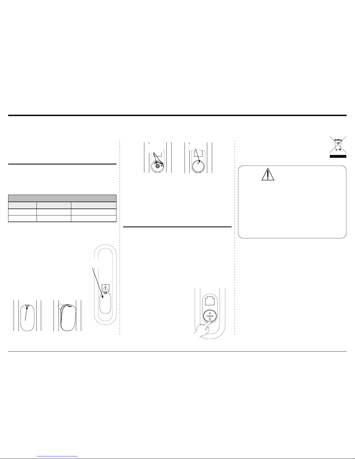
WARNING
DO NOT INGEST BATTERY, CHEMICAL BURN HAZARD
The remote control supplied with this product contains
a coin/button cell battery. If the coin/button cell battery
is swallowed, it can cause severe internal burns in just
2 hours and can lead to death. Keep new and used bat-
teries away from children. If the battery compartment
does not close securely, stop using the product and keep
it away from children. If you think batteries might have
been swallowed or placed inside of the body, seek im-
mediate medical attention.

3
3. Reinstall the Battery Cover.
4. Store the battery in a cool dry place for future use
or dispose of the battery in accordance
with the local regulations for lithium bat-
tery disposal. Batteries should never be
thrown away or incinerated.
The Wadia di122 Remote Control uses a long life Lith-
ium Coin Cell type battery. The di122 may be sup-
plied with a battery depending on the country where
the di122 is purchased. When purchasing a battery for
use in the di122 refer to the following list:
Approved Lithium Batteries
Brand ,(&1R $16,1('$1R
Energizer CR20di122 5004LC1
Panasonic &53$%15004LC1
1CR Lithium Coin Cells contain Perchlorate Material - special handling
may apply. For additional information go to www.dtsc.ca.gov/hazaedous
waste/perchlorate/index.cfm
Access to the recessed battery compartment is located
on the Rear of the Remote Control.
Refer to figure 1.
Perform the following steps to install
the battery:
1. Press the tab towards the bottom
edge of the Remote Control and
lift up on the Battery Cover and
temporarily place it aside. Refer to
figures 2 and 3.
The life of the Lithium Battery used in the Wadia
Remote Control is dependent on the actual amount of
use. It is advisable to remove the battery from the Re-
mote Control when it is not to be used for an extended
period of time. This will help to extend battery life
and avoid possible damage to the Remote Control.
Perform the following steps to remove the battery
from the Remote Control:
1. Press the tab and lift up on the Battery Cover
and temporarily place it aside. Refer to figures 2
and 3.
2. Referring to figure 6,
press on the bottom edge
of the battery to release
the battery from the
molded battery socket.
Then remove the bat-
tery from inside of the
Remote Control.
2. Remove the CR2032 Battery from its packaging.
3. Orient the battery so the + symbol (engraved into
RQHVLGHRIWKHEDWWHU\LVIDFLQJXS
4. Referring to figures 4 and 5, insert the battery
into the socket. Make sure the battery is touching
both contact points and is seated in the socket.
5. Reinstall the Battery Cover.
6. The Remote Control is now ready for operation.
Battery Installation and Replacement
Battery Installation
Battery Removal
CAUTION:
Danger of explosion if the battery is in-
correctly installed. Only install one of the
approved Lithium Batteries listed below.
Figure 1
Battery
Compartment
Figure 2
TAB
Figure 3
LIFT
UP
Figure 5
C
R
2
0
3
2
CR2032
3V
Figure 4
C
R
2
0
3
2
Contact
Points
Battery
WARNING
DO NOT INGEST BATTERY, CHEMICAL BURN HAZARD
The remote control supplied with this product contains
a coin/button cell battery. If the coin/button cell battery
is swallowed, it can cause severe internal burns in just
2 hours and can lead to death. Keep new and used bat-
teries away from children. If the battery compartment
does not close securely, stop using the product and keep
it away from children. If you think batteries might have
been swallowed or placed inside of the body, seek im-
mediate medical attention.
Figure 6

4
All of us at Wadia Digital would like to say thank you,
and congratulations for deciding to own this Wadia
di122 digital audio decoder. We sincerely believe this
Wadia product will bring you many years of musical
enjoyment and satisfaction.
Please take a short time to read the information in this
manual. We want you to be as familiar as possible
with all the features and functions of your new Wadia
Product.
Copyright 2014 © by Wadia Digital, LLC.
Table of ContentsThank You Please Take A Moment
Technical Assistance
If at any time you have questions about your Wadia
product, contact your Wadia Dealer who is familiar
with your Wadia equipment and any other brands that
may be part of your system. If you or your Dealer
wish additional help concerning a suspected problem,
you can receive technical assistance for all Wadia
products at:
Wadia Digital, LLC.
2 Chambers Street
Binghamton, New York 13903
Phone: 607-723-3539
Fax: 607-724-0549
Customer Service
If it is determined that your Wadia product is in need
of repair, you can return it to your Dealer. You can
also return it to the Wadia Service Department. For
assistance on factory repair return procedure, contact
the Wadia Service Department at:
Wadia Digital, LLC.
2 Chambers Street
Binghamton, New York 13903
Phone: 607-723-3539
Fax: 607-724-0549
The serial number, purchase date and Wadia Dealer
name are important to you for possible insurance
claim or future service. The spaces below have been
provided for you to record that information:
Serial Number: _______________________________
Purchase Date: _______________________________
Dealer Name: ________________________________
Safety Instructions ..................................................... 2
Battery Installation and Replacement........................ 3
Thank You and Please Take a Moment...................... 4
Technical Assistance and Customer Service ............. 4
Table of Contents ....................................................... 4
General Information .................................................. 5
Connector and Cable Information ............................. 5
Introduction................................................................ 6
Performance Features ................................................ 6
Dimensions ................................................................ 7
Installation ................................................................. 8
Connections:
AC/DC Adapter and Rear Panel Connections ............ 9
Connecting to a Preamplifier.................................... 10
Connecting to a Power Amplifier..............................11
Remote Control:
Remote Control Push-buttons................................... 12
Front Panel:
Front Panel Displays, Push-buttons .......................... 13
Operation:
How to Operate the di122 .................................... 14-17
Additional Information:
Photos........................................................................ 17
Specifications............................................................ 18
Packing Instruction................................................... 19
Wadia Digital, founded in 1988, is one of the
original companies dedicated to high performance
digital audio reproduction. Wadia is based on the
philosophy of applying advanced technology to
improve the performance of digital audio compo-
nents.
Wadia has consistently raised the standard for
performance of Digital Audio playback. Some of
the technological innovations pioneered by Wadia
include:
'LJL0DVWHUSDWHQWHGDOJRULWKP¿OWHURSWL-
PL]HGIRUUHSURGXFLQJPXVLF
&ORFN/LQNSURSULHWDU\MLWWHUUHGXFWLRQWHFK-
nology
6ZLIW&XUUHQWFXUUHQWWRYROWDJHFRQYHUVLRQ
technology
)LUVWRXWERDUG'LJLWDOWR$QDORJFRQYHUWHU
)LUVWWRDSSO\JODVV¿EHURSWLFVWRKRPHDXGLR
Our designs are born of a delicate balance of
technology shaped by a passion for music. Wadia
FRQWLQXHVWRUHGH¿QHWKHOLPLWVRIGLJLWDOPXVLF
playback.
About Wadia ....

5
1. For additional connection information, refer to the
RZQHU¶VPDQXDOVIRUDQ\FRPSRQHQWVFRQQHFWHG
to the di122 Digital Audio Decoder.
2. The Main AC Power going to the di122 and any
RWKHU:DGLD&RPSRQHQWVVKRXOGQRWEHDSSOLHG
until all the system components are connected
together. Failure to do so could result in mal-
functioning of some or all of the system’s normal
operations. When the di122 and other Wadia Com-
ponents are in their Standby Power Off Mode, the
Microprocessor’s Circuitry inside each component
is active.
3. The Unbalanced Outputs and Balanced Outputs can
be used simultaneously.
4. The di122’s internal Digital to Analog Converter
Circuitry is designed to decode 2-channel PCM
3XOVH&RGH0RGXODWLRQ'LJLWDO6LJQDOSUHVHQWDW
the Coaxial, Optical and USB Digital Inputs. Other
Digital Audio Signal Format Types will cause the
Audio Outputs of the di122 to be muted.
5. When discarding the unit, comply with local rules
or regulations. Batteries should never be
thrown away or incinerated but disposed
of in accordance with the local regulations
concerning battery disposal.
6. For additional information on the di122
and other Wadia Products please visit the Wadia
Web Site at www.wadia.com.
General Information and Connector Information
Connector and Cable Information
XLR Connectors
Below is the Pin configuration for the XLR Balanced
Output Connectors on the di122. Refer to the diagram
for connections:
PIN 1: Shield/Ground
PIN 2: + Output
PIN 3: - Output
Trigger Control Connectors
The Wadia di122 Trigger Input receives an On/Off
signal from +5 to +12 volts.
The Trigger Output will in
turn provide a +12 volt Output
Signal with a total current up to
25mA.
PIN 1 PIN 2
PIN 3
General Information
Trigger
Control
Ground
N/C

6
Introduction
Performance Features
Introduction and Performance Features
The Wadia di122 Digital Audio Decoder is one of the
finest Digital to Analog Processors ever created with
connections for digital sources including USB. The
di122 Outputs have the ability to drive multiple com-
ponents. The di122 reproduction is sonically transpar-
ent and absolutely accurate. The Wadia Sound is “The
Sound of the Music Itself.”
'XDO)XQFWLRQ
Use the Wadia di122 as the Digital Preamplifer
together with Digital Source Components and Power
Amplifier1to form a complete Audio System. Connect
the Wadia di122 to an exisiting Analog Audio System
to provide the latest in Digital-to-Analog Conversion
from digital audio sources.
(OHFWURQLF,QSXW6ZLWFKLQJ
Electronic Input Switching on all Inputs provides reli-
able, noiseless, distortion free switching.
%DODQFHG2XWSXWV
The Balanced Outputs allow the connection of long
cable lengths without a loss in sound quality.
'LJLWDO$XGLR,QSXWV
The di122 has Coaxial, Optical and USB Digital In-
puts to Decode PCM Signals from an external source.
The Coaxial and Optical Inputs process Digital
Signals up to 192kHz with 24Bit resolution. The USB
Input process PCM Digital Signals up to 192kHz with
32Bit resolution, decodes DSD128 Digital Signals and
';'%LWZLWKDVDPSOLQJUDWHRIRU
(66'LJLWDOWR$QDORJ&RQYHUWHU
The patented SABRE32 HyperstreamTM DAC architec-
ture and time Domain Jitter Eliminator is a 8 chan-
nel 32-bit, 192kHz Digital to Analog Converter. This
assures the music is reproduced with a wide dynamic
range and extremely low distortion for all Input
Sources.
3UHFLVLRQ7UDFNLQJ9ROXPH&RQWURO
Volume levels are controlled by a Digitally Controlled
Attenuator System.
$OSKDQXPHULF)OXRUHVFHQW'LVSOD\
The Front Panel Information Display indicates the
Source Selection, Bit Rate/Sampling Frequency and
Volume Level. The display intensity is adjustable.
5HPRWH&RQWURO
The Remote Control provides control of the di122
operating functions.
*ROG3ODWHG&RQQHFWRUV
The Output Connectors Contacts are gold plated for
superior corrosion resistance and high electrical con-
ductivity.
/(')URQW3DQHO,QGLFDWRUV
/RQJOLIH/LJKW(PLWWLQJ'LRGH/('LVXVHGWRLQGL-
cate when the di122 is in the Standby Mode.
'LH&DVW$OXPLQLXP&KDVLVV
Ensures the durability and functional design of the
di122 will be retained for many years.
1Note: The Wadia di122 is designed to be compatible with the
PDMRULW\RI$XGLR3RZHU$PSOL¿HUV+RZHYHUGXHWRD
ZLGHUDQJHRI3RZHU$PSOL¿HU'HVLJQVLWLVLPSRUWDQW
WKHLQSXWVHQVLWLYLW\RIWKHDPSOL¿HUEHDWOHDVW9ROWV
This will assure the playback of most music recordings
DUHUHSURGXFHGZLWKDGHTXDWHG\QDPLFUDQJH
SABRE32 and Hyperstream are registerted trademarks of ESS Technology

7
Dimensions
Dimensions
The following dimensions can assist in determining
the best location for your di122. There is additional
information on the next page pertaining to installing
the di122 into cabinets. Front View of the di122
10"
25.4cm
Rear View of the di122
VOLUME 35%
352.8kHz 3-5/32"
8cm
8"
20.3cm
Side View of the di122
10"
25.4cm
10"
25.4cm
8"
20.3cm

8
Installation
Installation
The di122 is designed to be placed upright on a table
or shelf, standing on its feet. The required ventilation
requirements are shown.
Always provide adequate ventilation for your di122.
Cool operation ensures the longest possible operating
life for any electronic instrument. Do not install the
di122 directly above a heat generating device, such
DVD3RZHU$PSOLILHU$OORZDWOHDVWLQFKHVFP
DERYHWKHWRSLQFKHVFPEHORZWKHERWWRP
DQGLQFKFPRQHDFKVLGHRIWKHGLVRWKDW
DLUIORZLVQRWREVWUXFWHG$OORZLQFKHVFPRI
depth for airflow and cable connections.
di122 Side View
14"
35.6cm
di122 Front View
2"
5.1cm
1"
2.5cm
1"
2.5cm
2"
5.1cm
VOLUME 35%
352.8kHz

9
AC/DC Adapter and Rear Panel Connections
DIGITAL INPUTS Optical Inputs 3
and 4 for source components with a
Digital Audio Optical Output
USB Digital Audio Input
with control signal for
connection to a computer
UNBALanced AUDIO OUTPUTS
analog audio output signals to a Pre-
amplifier or Power Amplifier
BALanced AUDIO OUTPUTS
analog audio output signals to a
Preamplifier or Power Amplifier
DIGITAL INPUTS Coaxial Inputs 1
and 2 for source components with a
Digital Audio Coaxial Output
Connect the supplied
AC/DC Power Adapter
DC Output Connnector
TRIGGER IN receives turn-on
signals from a component and
TRIGGER OUT sends turn-on
signals onto another component
Connect to the DC IN 5V connector
on the Rear Panel of the di122 Digital
Audio Decoder
&RQQHFWWRDOLYH$&RXWOHWDOZD\V2Q
using the supplied AC Power Cord. Re-
fer to information on the power supply
to determine the correct voltage
The AC/DC Power Adapter supplied
with the di122 Digital Audio Decoder

10
Connecting to a Preamplifier
There are two different ways the di122 may be oper-
ated in an audio system. The first way is as a Digital
to Analog Converter with Input Switching. The Audio
Output of the Wadia di122 is connected to an Analog
Input on the Preamplifier (Integrated Amplifier or Re-
FHLYHU7KHVHFRQGZD\LVDVWKH0DLQ$XGLR3UHDP-
plifier connected directly to a Power Amplifier; follow
instructions on the next page.
On this page is an example of a typical audio
system. Your system may vary from this, however the
actual components would be connected in a similar
manner. For additional information refer to “Connec-
tor and Cable Information” on page 5.
1RWH7KH2XWSXW&RQQHFWLRQ%DODQFHGRU8QEDO-
DQFHGPD\EHXVHGVLPXOWDQHRXVO\
$QDORJ$XGLR&RQQHFWLRQV
1. Connect audio cables from the di122 UNBAL-
DQFHG$8',228738765/5LJKWDQG/HIW
connectors to the unbalanced Aux Input Con-
nectors on the Preamplifier (A/V Control Center,
,QWHJUDWHG$PSOLILHURU5HFHLYHU
1RWH7KH%DODQFHG2XWSXWVPD\EHXVHGLQVWHDGRI
WKH8QEDODQFHG2XWSXWV
'LJLWDO$XGLR&RQQHFWLRQV
2. Connect a Digital Optical Cable from the di122
DIGITAL INPUTS OPTICAL 3 connector to the
CD Player Digital Optical Output connector.
3. Connect a Digital Coaxial Cable from the di122
DIGITAL INPUTS COAXIAL 1 connector to the
Server Digital Coaxial Output connector.
&RQQHFWD86%FDEOHZLWKW\SH$WRW\SH%FRQ-
nectors from the di122 DIGITAL AUDIO INPUT
USB connector to the Computer USB connector.
Trigger Control Connections:
5. Connect a Control Cable from the Preamplifier
Trigger Out Jack to the TRIGGER IN Jack on the
Wadia di122.
di122 supplied AC/
DC Power Supply
Connect to a
live AC Outlet
DOZD\V2Q
12 >:/G3@ SERVER
Computer
AUDIO OUTPUT
m
puter
6. Connect a Control Cable from the Wadia di122
TRIGGER OUT Jack to the CD
Player Trigger In Jack.
7. Connect a Control Cable from the
CD Player Trigger Out Jack to the
Server Trigger In Jack.
8. Connect any additional McIntosh
Components in a similar manner, as
outlined in steps 5 thru 8.
$&3RZHU&RUGV&RQQHFWLRQV
9. Connect the di122 AC Power Cord
to a live AC outlet.

11
Connecting to a Power Amplifer
The di122 may also be used as the Main Audio Pre-
amplifier connected directly to a Power Amplifier.
Follow the connection instructions below and diagram
on this page.
This is an example of a typical audio system. Your
system may vary from this, however the actual com-
ponents would be connected in a similar manner. For
additional information refer to “Connector and Cable
Information” on page 5.
1RWHV7KH2XWSXW&RQQHFWLRQ%DODQFHGRU8QEDO-
DQFHGPD\EHXVHGVLPXOWDQHRXVO\
)RUDGGLWLRQDOLQIRUPDWLRQRQ3RZHU$PSOL-
fier requirements when the Wadia di122 is
FRQQHFWHGGLUHFWO\WRD3RZHU$PSOLILHUUHIHU
WRSDJH11RWH
$XGLR&RQQHFWLRQV
1. Connect balanced audio cables from the di122 AU-
',228738765LJKWDQG/HIWFRQQHFWRUVWRWKH
balanced Input connectors on the Power Amplifier.
1RWH,IWZR3RZHU$PSOLILHUVDUHXVHGFRQQHFWWKH
XQEDODQFHG$8',22873876/5WRWKH
XQEDODQFHG,QSXWVRQWKHVHFRQG$PSOLILHU
'LJLWDO$XGLR&RQQHFWLRQV
2. Connect a Digital Optical Cable from the di122
DIGITAL AUDIO INPUTS OPTICAL 1 connector
to the CD Player Digital Optical Output connector.
3. Connect a Digital Coaxial Cable from the di122
DIGITAL AUDIO INPUTS COAXIAL 1 connec-
tor to the Server Digital Coaxial Output connector.
&RQQHFWD86%FDEOHZLWKW\SH$WRW\SH%FRQ-
nectors from the di122 DIGITAL AUDIO INPUT
USB connector to the Computer USB connector.
$&3RZHU&RUGV&RQQHFWLRQV
5. Connect the di122 AC Power Cord to a live AC
outlet.
Connecting to a Power Amplifier
di122 supplied AC/
DC Power Supply
Connect to a
live AC Outlet
DOZD\V2Q
12 >:/G3@ SERVER
Computer
m
put
er
3RZHU$PSOL¿HU

12
Remote Control Push-Buttons
1RWH3XVKEXWWRQVZKRVHIXQFWLRQLVQRWLGHQWLILHGDERYHDUHIRUXVHZLWKRWKHU:DGLD3URGXFWV
3UHVVWKHRUWRDGMXVWWKH
Volume Level Up or Down
Steps thru the Digital Inputs
IRUVRXUFHVHOHFWLRQ
Press MODE to switch
Power On or Off to the
di122
Mutes the audio
Press and hold to change the
Auto Power Off from Enabled
to Disabled
Press DISPLAY to change
from displaying normal
status to a single dot
Press to adjust the
Channel Balance

13
VOLUME 35%
352.8kHz
STANDBY/ON Push-button with indicator,
VZLWFKHVWKHGL21RU2))6WDQGE\,W
will also increase the volume level when the
Volume Adjust Mode is active.
INPUT selection of digital sources for
decoding. VOLumn down is also used
to select the Volume Adjust Mode and
then will decrease the volume level.
Front Panel DISPLAY indicates the Source, Vol-
ume Level Percentage, Sampling Frequency and
Operational Functions.
Front Panel Displays, Controls, Push-buttons and Jack
IR Sensor receives
commands from a
Remote Control
Connection for dynamic
type headphones, for
private listening

14
dicate “VOLUME MUTE”. Refer to figure 54. Press-
ing the MUTE Push-button a second time or adjust the
Volume Level to un-mute the di122.
%DODQFH
Listening balance varies with
different program sources, room
acoustics and listening positions
relative to the Loudspeakers. Use
Balance as needed to achieve ap-
proximately equal listening volume
levels in each Loudspeaker. To
adjust the Balance perform the fol-
lowing:
1. Press and release the Push-
button on the Remote Control
to decrease the volume level of
the Right Channel in one decibel
LQFUHPHQWVXSWRG%³%$/-
ANCE, L:0dB R:-30dB” ap-
pears on the Front Panel Display.
Refer to figures 54, 55 and 58.
9ROXPH/HYHO
To change the Volume Level of the Wadia di122, use
WKH9ROXPH'RZQ3XVKEXWWRQRUWKH
9ROXPH8S3XVKEXWWRQRQWKH5HPRWH&RQWUROIRU
the desired listening level. The Volume Level may also
be changed by using the Volume Adjust Mode and the
Front Panel INPUT / VVOL and STANDBY/ON / U
VOL Push-buttons. To activate Volume Adjust Mode
press and hold in the INPUT / VVOL Push-button.
The Front Panel Display will now show arrows on ei-
ther side of the current volume setting. Refer to figure
53. Then press the VVOL or UVOL Push-buttons to
either increase or decrease the Volume to the desired
level. When the arrows disappear from the Front Panel
Display, the Volume Adjust Mode will be deactivated.
Refer to figures 51, 53 and 58.
0XWH
Press the Remote Control MUTE Push-button to
mute the Audio Outputs. Refer to figure 58. When the
Wadia di122 is muted, the Front Panel Display will in-
3RZHU2QDQG2II
The Red LED above the STANDBY/ON Push-button
lights to indicate the di122 is connected to AC Power.
To switch ON the di122, press the STANDBY/ON
Push-button on the Front Panel or the MODE (Power
2Q3XVKEXWWRQRQWKH5HPRWH&RQWURO7KHGL
will go through a brief startup initialization and
with the Front Panel Display indicating the last used
Volume Level Setting. Refer to figures 50, 51, 52 and
58. To switch OFF the di122 press the STANDBY/ON
Push-button on the Front Panel or the MODE (Power
2II3XVKEXWWRQRQWKH5HPRWH&RQWURO
6RXUFH6HOHFWLRQ
Press the INPUT Push-button on the Front Panel or on
the Remote Control to select the desired source. Refer
to figures 51, 52 and 58.
How to Operate the di122
VOLUME 35%
352.8kHz
Figure 52
Figure 58
How to Operate the di122
Figure 50
VOLUME 35%
___
Figure 53
ÅVOLUME 35% Æ
DSD128
VOLUME MUTE
384kHz
Figure 54
Figure 51
INPUT: 1 (COAX)
___
Figure 55
BALANCE
L:0dB R:0dB
BALANCE
L:0dB R:-30dB
Figure 56

15
Remote Control until the Front Panel Display will
indicate “AUTO POWER OFF, : ENABLE”. Refer
to figure 59.
2. Then press and hold the ENTER Push-button a
second time and the display will then indicate
“AUTO POWER OFF, : DISABLE”. Refer to
figure 60.
3. The Auto Power Off feature is now disabled. To
re-activate the Auto Power Off feature repeat steps
1 and 2.
86%,QSXW2SHUDWLRQDQG'ULYHU,QVWDOODWLRQ
The di122 USB Input provides the capability to play
back music from a computer when the di122 Rear
Panel USB Connector is connected to a computer USB
Connector. Refer to figure 61.
1RWH7KH86%,QSXWLVIRUGLUHFWFRQQHFWLRQWRDFRP-
SXWHURQO\7RSOD\EDFNPXVLFIURPD86%'ULYH
FRQQHFWWKH86%'ULYHWRDQRWKHU86%3RUWRQ
WKHFRPSXWHUDQGVHOHFWWKH86%'ULYHZLWKWKH
0HGLD3OD\EDFN3URJUDP
2. Press and release the Push-button on the
Remote Control to decrease the volume level of
the Left Channel in one decibel increments (up to
G%³%$/$1&(/G%5G%´DSSHDUV
on the Front Panel Display. Refer to figures 57
and 58.
After approximately 3 seconds, the Display returns to
indicate the Volume Level and Sampling Rate.
Note: The di122 will retain any changes made to the
&KDQQHO%DODQFHXQWLOLWLVFKDQJHGDJDLQ
'LVSOD\RI6DPSOLQJ5DWH
The Wadia di122 indicates the digital sampling rate
for all of the Input Sources connected to the Digital
Audio Decoder. Referring to figure 53, the second line
of the Front Panel Display is indicating the di122 is
receiving a DSD128 Digital Signal, via the USB Input.
When there is no digital signal present for the selected
Input Source the Front panel Display will indicate “ - -
-”. Refer to figure 50.
$XWR3RZHU2II
The di122 incorporates an Auto Power Off Feature,
which can automatically place the Digital Audio
Decoder into the Power Saving Standby/Off Mode.
This occurs approximately 2 hours after there has
been an absence of user activity. User activity includes
changes to any of the Operation Functions such as
source selection, volume adjustment, etc. If it is
desirable to disable the Auto Off Power Save Feature
perform the following steps:
1. Press and hold the ENTER Push-button on the
AUTO POWER OFF
: DISABLE
Figure 60
AUTO POWER OFF
: ENABLE
Figure 59
Figure 61
INPUT: USB
192kHz
The di122 USB Input is compatible with PC
&RPSXWHUVXVLQJ0LFURVRIW:LQGRZV9LVWD63
:LQGRZV63DQG:LQGRZV63,WLVDOVRFRP-
patible with Apple® Macintosh® Computers using
OS-10.9 Mavericks or later.
When using a PC Computer with Windows, a spe-
cial Wadia USB Audio Software Driver needs to be
installed on the PC Computer. The driver needs to be
installed before connecting the di122 USB Input to the
USB Port on the computer.
Note: If an Apple Macintosh computer is used with the
GLQRDGGLWLRQDOGULYHULVUHTXLUHG
The Wadia USB Audio Windows Driver is avail-
able for download from the Wadia Web Site:
KWWSZZZ:DGLDFRPHQXVSURGXFWVGL
Under “Products” select “Wadia di122” then
scroll down to the bottom of the Wadia di122 to the
“DOWNLOAD AREA”. Select the “WADIA di122
PC DRIVER SETUP” and download the PC Windows
Driver. Follow the instructions below to install the
Wadia di122 Driver:
3XUSRVH To Install the Wadia USB Audio Windows
Driver for use with Wadia Products with
an USB-Digital Audio Input.
5HTXLUHPHQWV 1. A functioning Wadia Product with
an USB-Digital Audio Input.
2. A PC Computer with aJHQXLQH
Intel Main Processor and a
functioning USB Port.
:LQGRZV9LVWD63:LQGRZV
63RUJUHDWHURU:LQGRZV
63RUJUHDWHU2SHUDWLQJ
System.
4. An USB Cable with Type A to
Type B Connectors.
BALANCE
L:-30dB R:0dB
Figure 57

16
FRPSXWHUDQ
additional
³:DGLD86%
Audio”
playback
GHYLFHZLOO
appear in the
OLVWLQJ0DNH
sure to select
the “Wa-
GLD'LJLWDO
86%'ULYHU
´IURP
DYDLODEOHSOD\EDFNGHYLFHVOLVWHGZKHQXV-
LQJWKLV:DGLD3URGXFWIRU86%$XGLR
86%0XVLF3OD\EDFN
When the USB Input is selected on the Wadia di122,
the Front Panel Display indicates the Sampling Rate
UHIHUWRILJXUHVDQGIRU3&06LJQDOV)LJXUHV
12 and 13 indicate a Sampling Rate of 64 or 128 times
the Sampling Rate of a CD Disc for the incoming
Digital Audio Signal.
nectors between the PC Computer and the Wadia
Product with the USB-Digital Audio Input. An Icon
will appear On-Screen
indicating Windows
has found new hard-
ware. Refer to figure
5. When the driver
has been successfully
installed figure 6 will
appear.
:LQGRZV6RXQG6HWWLQJV
For proper operation of the Wadia Product via the
Computer USB Connection, it is required to make
changes to Windows Sound Settings:
1. Click on the “Sound” (located in the Windows
&RQWURO3DQHOWKHQVHOHFWWKH'LJLWDO2XWSXW
“WADIA DIGITAL USB Driver _._.__” icon.
Using the “Set Default” button to set the just se-
lected Wadia Icon as the default. Refer to figures
7, 8 and 9.
1RWHV:KHQWKH:DGLD86%$XGLR3URGXFWLVQRW
FRQQHFWHGWR\RXUFRPSXWHUWKHSUHYLRXV
GHIDXOW$XGLR'HYLFHZLOOEHVHOHFWHG
,IRWKHU:DGLD3URGXFWVZLWK86%$XGLR
&RQQHFWLRQVDUHDOVRFRQQHFWHGWRWKH
,QVWDOOLQJWKH6RIWZDUH
It is important to first install the downloaded software
on your computer before connecting the Wadia Prod-
uct to the computer. The USB Driver is included in the
downloaded software package.
1RWH%HIRUHLQVWDOOLQJWKLVVRIWZDUHSOHDVHFKHFNWRVHH
LIWKH:DGLD3URGXFWVZLWKWKH86%'LJLWDO$XGLR
,QSXWKDVWKHODWHVWILUPZDUHYHUVLRQLIQRWXSGDWH
WKHILUPZDUHILUVW
1. Unzip the downloaded Wadia Windows USB
Driver Software Package.
2. Run ³:DGLDB86%BGULYHUBBH[H´. Refer to figure 1.
3. Referring to figure 2, check the Always trust soft-
ZDUHIURP³$PDQHUR65.´box and then the Install
button.
4. When the Driver has been installed click on the
“Finish” button. Refer to figures 3 and 4.
86%&RQQHFWLRQ
Connect the USB Cable with Type A to Type B con-
Figure 5
Figure 6
Figure 7 Figure 8
Figure 9
How to Operate the di122, con’t
Figure 10
INPUT: USB
192kHz
Figure 11
VOLUME 35%
352.8kHz
Figure 12
VOLUME 35%
DSD64
Figure 1 Figure 2
Figure 3 Figure 4

17
The Sampling Rate and the Bit Rate is determined by
the original recording and/or the Windows Application
6HWWLQJVIRU2XWSXW)RUPDWZKHQDYDLODEOH
1RWH,QJHQHUDOZKHQWKHRULJLQDOPXVLFLVUHFRUGHG
DWDKLJKHU6DPSOLQJ5DWHWKHUHVXOWLVXVXDOO\
PRUHGHWDLOLQWKHPXVLF+RZHYHUWKLVKLJKHU
rate results in consuming larger amounts of stor-
DJHVSDFH7KH6DPSOH5DWHXVXDOO\VKRXOGEHVHW
WRPDWFKWKH6DPSOH5DWHRIWKHPXVLFUHFRUGLQJ
EHLQJSOD\HGEDFN
There are many third party Windows Applications
EHVLGHV:LQGRZV0HGLD3OD\HUIRUVWHDPLQJPXVLF
from the computer to Wadia di122 USB Input. An
example of just one of the available applications is
“JRiver Media Center”.
How to Operate the di122, con’t and Photos
Figure 13
VOLUME 35%
DSD128

18
Specifications
)UHTXHQF\5HVSRQVH
+/-0.5dB from 20Hz to 20,000Hz
7RWDO+DUPRQLF'LVWRUWLRQ
0.005%
9DULDEOH2XWSXWOHYHO
0 - 4.0Vrms Unbalanced
0- 8.0Vrms Balanced
6LJQDO7R1RLVH5DWLR$:HLJKWHG
105dB
'\QDPLF5DQJH
98dB
2XWSXW,PSHGDQFH
/HVVWKDQRKPV8QEDODQFHGDQG%DODQFHG
Audio Specifications Digital Audio Specifications General Specifications
3RZHU5HTXLUHPHQWV
100-240 Volts, 50/60Hz at 10 Watts
Standby: Less than 0.5 watt
1RWH2QO\XVHWKH$&'&3RZHU$GDSWHUVXSSOLHGZLWK
WKH:DGLDGL
2YHUDOO'LPHQVLRQV
:LGWKLVLQFKHVFP
+HLJKWLVLQFKHVFPLQFOXGLQJIHHW
'HSWKLVLQFKHVFPLQFOXGLQJWKH)URQW3DQHO
and Cables
:HLJKW
SRXQGVNJQHWSRXQGVNJLQVKLSSLQJ
carton
6KLSSLQJ&DUWRQ'LPHQVLRQV
:LGWKLVLQFKHVFP
+HLJKWLVLQFKHVFP
'HSWKLVLQFKHVFP
'LJLWDO,QSXW6LJQDO)RUPDW
Coaxial and Optical Inputs - SPDIF (PCM1
USB Input - PCM1, DSD
'LJLWDO,QSXW6DPSOH5DWH
Coaxial and Optical: 44.1kHz to 192kHz, 24-Bit
86%N+]WRN+]%LW3&0
DSD64, DSD128, DXD352.8kHz, DXD384kHz
'LJLWDO,QSXWV
Coaxial 1 and 2: 0.5V p-p/75 ohms
2SWLFDODQGGEPWRGEP726/LQN
USB: USB Type B Connector
1 3&03XOVH&RGH0RGXODWLRQ'LJLWDO6LJQDOW\SHXVHGIRU
CD Discs, etc.
Trigger Specifications
7ULJJHU,QSXW
5-15VDC, less than 1mA
7ULJJHU2XWSXW
12VDC, 25mA maximum total

19
Packing Instructions
In the event it is necessary to repack the equipment for
shipment, the equipment must be packed exactly as
shown below. It is very important to ensure the proper
equipment location between the bottom and top foam
pads. Failure to do this will result in shipping damage.
Use the original shipping carton and interior parts
only if they are all in good serviceable condition. If
DVKLSSLQJFDUWRQRUDQ\RIWKHLQWHULRUSDUWVDUH
needed, please call or write Customer Service Depart-
ment of Wadia. Refer to page 4. Please see the Part
List for the correct part numbers.
Quantity Part Number Description
1 03456100 Shipping carton only
1 03456200 Top foam pad
1 03456000 Bottom foam pad

The continuous improvement of its products is
the policy of Wadia Digital who reserve the right
to improve design without notice. Printed in the
U.S.A.
Wadia Digital, LLC
2 Chambers Street
Binghamton, NY 13903
www.wadia.com
Wadia Digital Part No. 04152300
Other manuals for di122
1
Table of contents
Other Wadia Media Converter manuals
Popular Media Converter manuals by other brands

Alpha Technologies
Alpha Technologies CXDF 48-24/2kW Installation & operation manual

Trinity
Trinity Silver Reference Series manual

Procon
Procon MelCOMMS MINI installation manual

PCB Piezotronics
PCB Piezotronics 422E16 Installation and operating manual

Miele
Miele Segosoft SegoSerial Industrial Grade... Installation and administration

ANTAIRA
ANTAIRA STF-502C series Quick installation guide