Waeco magic heat MSH-50 User manual

Montage- und Bedienungsanleitung
Installation and Operating Instructions · Instrucciones de montaje y de servicio · Instructions de
montage et de service · Istruzioni di montaggio e d’uso · Montage- en bedieningshandleiding ·
Monterings- og betjeningsvejledning · Monterings- och bruksanvisning · Monterings- og
bruksanvisning · Asennus- ja käyttöohje
MSH-50
✎Symbole 2
DNachrüstbare Sitzheizung 7
GB Retrofittable seat heating 15
Calefacción del asiento como aditamento adicional 23
Chauffage de siège, montage ultérieur 31
Riscaldamento sedili addizionale 39
In te bouwen stoelverwarming 47
Sædevarme til eftermontering 55
Stolvärmeanordning för montering i efterhand 63
Ettermonterbar setevarmer 71
Jälkikäteen asennettava istuinlämmitys 79
E
F
I
NL
DK
S
N
FIN
magic heat
E13
10R-02 1087
msh-50_q4 15/09/03 9:32 Page 1

3
A
B
1
34
1
3
2
- Heizelement Sitzfläche
- heating element, seat
- Heizelement Lehne
- heating element, backrest
- Anschlusskabel mit Relais und Schalter
- connection cable with relay and switch
2
msh-50_q4 15/09/03 9:32 Page 3

4
123
456
8
9
10
13
12
C
14
11
7
msh-50_q4 15/09/03 9:32 Page 4

5
1
D
23
456
789
10 11 12
msh-50_q4 15/09/03 9:32 Page 5

6
1
Masse (31)
Ground (31)
rot/red
orange/orange
schwarz/black
+12 Volt Dauerplus (30)
+12 volts permanent (30)
+12 Volt geschaltetes Plus (15)
+12 volts Ignition (15)
✃
✃
ca. 20 mm
2
E
msh-50_q4 15/09/03 9:32 Page 6

Warnung! Sicherheitshinweis!
Nichtbeachtung kann zu Personen- oder Materialschäden führen.
Die Raute kennzeichnet Einbauschritte, die Sie ausführen müssen.
Damit der Einbau ohne Schwierigkeiten stattfindet, diese Montage-
und Bedienungsanleitung vor Beginn der Montage durchlesen.
Bei einem Besitzwechsel von MSH-50 muss diese Montage- und
Bedienungsanleitung mit übergeben werden.
Sollte die Anleitung nicht alle Ihre Fragen beantworten oder sollten
Montageschritte nicht klar sein, fragen Sie bitte unbedingt unseren
technischen Kundenservice.
WAECO International GmbH
D-48282 Emsdetten
Hollefeldstraße 63
Tel. +49 (0) 25 72/87 91 91
Fax +49 (0) 25 72/87 93 91
www.waeco.de
7
Hinweise zur Benutzung der Einbauanleitung . . . . . . . . . . . . . . . . . 7
Allgemeine Produktbeschreibung . . . . . . . . . . . . . . . . . . . . . . . . . . 7
Hinweise zur Benutzung der Einbauanleitung . . . . . . . . . . . . . . . . . 7
Sicherheits- und Einbauhinweise . . . . . . . . . . . . . . . . . . . . . . . . 8-10
Lieferumfang . . . . . . . . . . . . . . . . . . . . . . . . . . . . . . . . . . . . . . . . . 10
Benötigtes Werkzeug . . . . . . . . . . . . . . . . . . . . . . . . . . . . . . . . . . . 10
Montage der Sitzheizung . . . . . . . . . . . . . . . . . . . . . . . . . . . . . 11-12
Technische Daten . . . . . . . . . . . . . . . . . . . . . . . . . . . . . . . . . . . . . 13
Entsorgungshinweis . . . . . . . . . . . . . . . . . . . . . . . . . . . . . . . . . . . 13
Inhaltsverzeichnis
Hinweise zur Benutzung der Einbauanleitung
◆
Die WAECO magic heat Sitzheizung ist ein Komfortprodukt für den
Einbau in die Fahrzeugsitze. Die Form des Sitzes wird durch die
Heizelemente nicht verändert. Die Bedienung der Sitzheizung erfolgt
über je einen Schalter für den Fahrer und Beifahrersitz. Innerhalb kurzer
Zeit ist die angenehme Wärme spürbar.
Allgemeine Produktbeschreibung
msh-50_q4 15/09/03 9:32 Page 7

Warnung! Unzureichende Leitungsverbindungen können zur Folge
haben, dass durch Kurzschluss:
•Kabelbrände entstehen
•der Airbag ausgelöst wird
•elektronische Steuerungseinrichtungen beschädigt werden
•elektrische Funktionen (Blinker, Bremslicht, Hupe, Zündung,
Licht) ausfallen
Beachten Sie deshalb folgende Hinweise:
Bei Arbeiten an den Leitungen des Fahrzeuges gelten folgende
Klemmenbezeichnungen:
30 (Eingang von Batterie Plus direkt),
15 (Geschaltetes Plus, hinter Batterie)
31 (Rückleitung ab Batterie, Masse)
Bei allen Arbeiten sind die entsprechenden Herstellerangaben zu
beachten.
Bei Fahrzeugen mit Seitenairbags in den Sitzlehnen,
Sitzbelegungserkennung oder Kindersitzerkennung sind die
entsprechenden Herstellerangaben des jeweiligen
Fahrzeugherstellers zu beachten.
8
Sicherheits- und Einbauhinweise
Die sicherste Verbindungsart ist, die Kabelenden miteinander zu
verlöten und anschließend zu isolieren.
Bei wiederlösbaren Verbindungen nur isolierte Kabelschuhe, Stecker
und Flachsteckhülsen verwenden. Keine Quetschverbinder
(Leitungsverbinder) oder Lüsterklemmen verwenden.
Zum Verbinden der Kabel mit Kabelschuhen, Stecker oder
Flachsteckhülsen eine Krimpzange verwenden.
Bei Kabelanschlüssen an 31 (Masse):
Das Kabel mit Kabelschuh und Zahnscheibe an eine fahrzeugeigene
Masseschraube schrauben oder mit Kabelschuh, Blechschraube und
Zahnscheibe an das Karosserieblech schrauben.
Auf gute Masseübertragung achten!
msh-50_q4 15/09/03 9:32 Page 8

Warnung! Wegen Kurzschlussgefahr vor Arbeiten an der
Fahrzeugelektrik immer den Minuspol der Batterie abklemmen.
Bei Fahrzeugen mit Zusatzbatterie ebenfalls den Minuspol
abklemmen.
Achtung! Beim Abklemmen des Minuspols der Batterie verlieren
alle flüchtigen Speicher der Komfort-Elektronik ihre
gespeicherten Daten. Folgende Daten müssen Sie je nach
Fahrzeugausstattung neu eingeben:
Radiocode, Fahrzeuguhr, Zeitschaltuhr, Bordcomputer, Sitzposition
Hinweise zur Einstellung können Sie in der jeweiligen
Bedienungsanleitung nachlesen.
Warnung! Im Fahrzeug montierte Teile des Gerätes müssen so
befestigt werden, dass sie sich unter keinen Umständen
(scharfes Abbremsen, Verkehrsunfall) lösen können und zu
Verletzungen der Fahrzeuginsassen führen können.
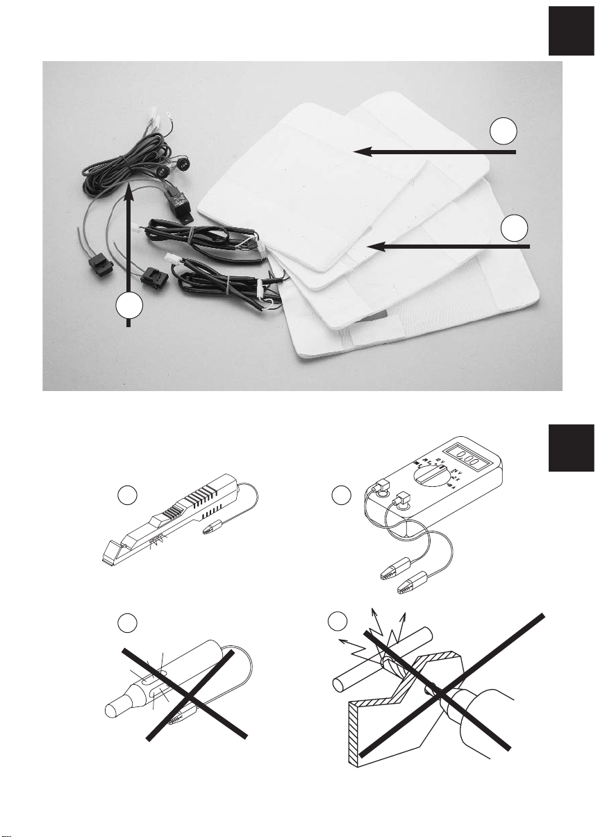
Achtung! Zum Prüfen der Spannung in elektrischen Leitungen
darf nur eine Diodenprüflampe (siehe B 1) oder ein Voltmeter
(siehe B 2) benutzt werden. Prüflampen (siehe B3) mit einem
Leuchtkörper nehmen zu hohe Ströme auf, und die
Fahrzeugelektronik kann beschädigt werden.
Achtung! Um Schäden zu vermeiden, auf ausreichenden
Freiraum für den Bohreraustritt (siehe B4) achten. Jede Bohrung
entgraten und mit Rostschutzmittel behandeln.
9
Spitze und schwere Gegenstände dürfen nicht auf den Sitz gelegt
werden da sonst die Sitzheizung beschädigt werden kann. Bei Personen
mit gestörtem Wärmeempfinden empfiehlt es sich, magic heat nur in der
Stufe I zu betreiben. Bei eingeschalteter Sitzheizung dürfen keine
Wärmedämmenden Gegenstände wie Decken oder Mäntel auf den Sitz
gelegt werden. Die Sitzheizung kann durch verschüttete Flüssigkeiten
auf dem Sitz beschädigt werden. Die Sitzheizung darf niemals im
nassen Zustand eingeschaltet werden.
Sicherheits- und Einbauhinweise
msh-50_q4 15/09/03 9:32 Page 9

Achtung! WAECO International übernimmt keine Haftung für
Schäden, aufgrund folgernder Punkte:
a) Montagefehler
b) Beschädigungen am System durch mechanische Einflüsse
und Überspannungen
c) Veränderungen am Gerät ohne ausdrücklicher Genehmigung
von WAECO International
d) Verwendung für andere als die in der Montageanleitung
beschriebenen Zwecke.
Nr. Menge Bezeichnung Artikel-Nr.
12 Heizelement Sitzfläche (siehe A1) MSH-S-50
22 Heizelement Lehne (siehe A2) MSH-L-50
31 Anschlusskabel (siehe A3) MSH-KA-50
m. Relais u Schalter
44 Doppelseitiges Klebeband
Lieferumfang
Benötigtes Werkzeug
Für Einbau und Montage werden benötigt:
–Maßstab (siehe C 1) – Bohrmaschine (siehe C 5)
–Körner (siehe C 2) – Schraubendreher (siehe C 6)
–Hammer (siehe C 3) – Schraubenschlüssel (siehe C 7)
–Bohrer (siehe C 4)
Für den elektrischen Anschluss und die Überprüfung werden benötigt:
–Diodenprüflampe (siehe C 8) – Heißluftföhn (siehe C 12)
oder Voltmeter (siehe C 9) – Lötkolben (siehe C 13)
–Krimpzange (siehe C 10) – Lötzinn (siehe C 14)
–Isolierband (siehe C 11)
Bedingt durch Ihre individuelle Montage benötigen Sie evtl. zur
Befestigung andere Schrauben, Muttern, Unterlegscheiben,
Blechschrauben und Kabelbinder als die im Lieferumfang enthaltenen.
10
Sicherheits- und Einbauhinweise
msh-50_q4 15/09/03 9:32 Page 10

11
Montage
1. Demontage der Sitze. Das Fahrzeug muss gegen Wegrolle
gesichert werden. Bei Fahrzeugen mit Seitenairbags in der
Sitzlehne müssen die Herstellerangaben zur Demontage der
Sitze und Polster beachtet werden.
Nach der Überprüfung der Einbaubarkeit (anhand dieser
Einbauanleitung und der Herstellerinformation) sollten die
Fahrzeugsitze demontiert werden. Entfernen Sie hierzu die
Befestigungsschrauben und heben Sie den Sitz aus dem
Fahrzeug.
2. Entfernen Sie alle Kunststoffverkleidungen des Sitzes, um die
Befestigungen des Bezugstoffes erreichen zu können.
3.Trennen Sie die Lehne von der Sitzfläche (siehe D 1 und D 2)
4. Öffnen Sie den Sitzbezug der Sitzfläche. Der Bezugsstoff ist
meist mit einer breiten Pappe oder einem Metalldraht in einer
Falz am Untergestell eingeklemmt. Die Befestigungen lassen
sich mit einem Schraubendreher und einer Zange lösen
(siehe D 3 und D 4).
5. Lösen Sie evtl. vorhandene Polsterklammern oder
Querstreben (siehe D 5)
6. Das Heizelement für die Sitzfläche kann nun zwischen
Bezugsstoff und Schaumkern der Sitzfläche eingeführt
werden (siehe D 6).
Zur Überbrückung der Abnähgräben bzw. der Querstreben,
mit denen der Sitzbezug zusätzlich auf dem Schaumkern
befestigt wird, ist an dem Heizelement der Sitzfläche eine
Aussparung vorgesehen. Je nach Sitz kann dieser Bereich
durch den Abnähgraben geführt werden (siehe D 7) oder
durch Einschnitte in den Querstrebentunnel gelegt werden.
Fixieren Sie die Heizelemente mit doppelseitigem Klebeband
gegen Verrutschen auf dem Schaumstoffkern. Es ist darauf
zu achten, dass sich keine Falten oder Knicke bilden.
msh-50_q4 15/09/03 9:32 Page 11

12
10.Elektrischer Anschluss
Suchen Sie einen geeigneten Einbauort für die
Sitzheizungsschalter. Wenn möglich, sollten hierfür
vorhandene Blindkappen benutzt werden. Stellen Sie sicher,
dass hinter der Verkleidung genügend Platz für die Montage
des Schalters vorhanden ist.
Zeichnen Sie den Schalterausschnitt mit der beiliegenden
Schablone an. Sparen Sie den markierten Bereich mit
entsprechendem Werkzeug aus. (siehe E 1)
Verlegen Sie den vorgefertigten Kabelbaum, ohne dass die
Kabel einknicken bzw. durchscheuern können (siehe D 11).
Es ist besonders im Bereich der Sitzschienen auf eine sichere
Verlegung zu achten. Zum elektrischen Anschluss (siehe E 2).
ACHTUNG! Sollte es erforderlich sein, Schnitte in dem
Heizelement vorzunehmen, so ist auf den Verlauf der
Heizleitungen zu achten. Diese Leitungen dürfen nicht
beschädigt und extrem geknickt werden.
7.Der Einbau des Heizelementes in die Lehne verläuft wie der
Einbau in die Sitzfläche.
8. Der Bezug der Lehne kann in dem unteren Bereich geöffnet
werden (siehe D 8).
9. Das Heizelement wird in den Zwischenraum zwischen
Sitzbezug und Sitzpolster eingeschoben und mit
doppelseitigem Klebeband faltenfrei fixiert (siehe D 9)
Die Heizfläche muss nur ca. 30-35 cm über die Sitzfläche
reichen, da sich der Fahrer bei einer normalen Sitzposition
nur in diesem Bereich anlehnt. Sind die Sitze mit
Seitenairbags ausgestattet, so ist der Bezugsstoff mit
Sollbruchstellen versehen. Der Sitzbezug darf daher nicht zu
stark gezogen oder verschoben werden.
Montage
msh-50_q4 15/09/03 9:32 Page 12

13
Betriebsspannung: 12 Volt
Stromaufnahme: 1. Stufe 1,87 A je Sitz
2. Stufe 3,75 A je Sitz
Maße: Sitzelement 400 x 280 mm
Lehnenelement 300 x 280 mm
Technische Daten
Entsorgungshinweis
Beachten Sie bitte, dass elektrische Geräte eine Vielzahl
wiederverwertbarer Materialien sowie umweltschädliche Komponenten
enthalten.
Tragen Sie bitte in Ihrem und im Interesse der Umwelt Sorge dafür, dass
diese Komponenten nur über die vorgesehenen und zugelassenen Wege
entsorgt werden.
msh-50_q4 15/09/03 9:32 Page 13

14
msh-50_q4 15/09/03 9:32 Page 14

Warning! Safety instruction:
Failure to observe these warnings may result in injuries to persons
or damage to material.
The rhombus marks installation steps which you have to
implement.
To ensure a problem-free installation, read these assembly and
operating instructions carefully before starting the installation.
Hand over the assembly and operating instructions when
passing on the MSH-50 to a new proprietor.
If the operating instructions do not answer all your questions, or
if the assembly steps are not clear, please do not hesitate to
contact our customer technical support service.
WAECO UK Ltd.
UK-Broadmayne · Dorset DT2 8LY
Unit G1 · Roman Hill · Business Park
phone: +44-13 05/85 40 00
fax: +44-13 05/85 42 88
www.waeco.com
15
General product description . . . . . . . . . . . . . . . . . . . . . . . . . . . . . . 7
Information on using the installation instructions . . . . . . . . . . . . . . . 7
General safety and installation instructions . . . . . . . . . . . . . . . . . 8-10
Scope of delivery . . . . . . . . . . . . . . . . . . . . . . . . . . . . . . . . . . . . . 10
Required tools . . . . . . . . . . . . . . . . . . . . . . . . . . . . . . . . . . . . . . . . 10
Installing the seat heating . . . . . . . . . . . . . . . . . . . . . . . . . . . . . 11-12
Technical data . . . . . . . . . . . . . . . . . . . . . . . . . . . . . . . . . . . . . . . . 13
Disposal instructions . . . . . . . . . . . . . . . . . . . . . . . . . . . . . . . . . . . 13
Table of contents
Information on using the installation instructions
◆
The WAECO magic heat seat heating is a convenience product intended
for the installation in the vehicle seats. The shape of the seats is not
modified by the heating elements. The seat heating is operated by
separate switches for the driver and passenger seats. The comfortable
warmth can be felt within a short period of time.
General product description
msh-50_q4 15/09/03 9:32 Page 15

Warning! Inadequate cable connections can lead to short-circuits
which cause the following:
•cable fires
•activation of the airbag
•damage to electronic control equipment
•electrical functions (blinkers, brake lights, horn, ignition, lights)
fail.
The following indications must be therefore considered:
With respect to works on the lines of the vehicle the following
terminal designations apply:
30 (input from battery plus direct),
15 (switched plus, behind battery)
31 (return cable from battery, earth)
The respective manufacturer’s specifications are to be observed
with respect to all works you carry out.
The relevant specifications of the respective vehicle
manufacturer have to be observed with respect to vehicles that
are equipped with side airbags in the seat backrests, a seat
occupation detection, or a child seat detection system.
16
Safety and installation instructions
The securest form of connection is obtained by soldering the cable
ends and then insulating the connection.
For detachable connections, only use insulated cable brackets,
connector plugs, and flat pin bushings. Do not use crimp connections
(line connectors) or luster terminals.
Use crimp pliers for connecting the cables with cable lugs, plugs, or flat
pin bushings.
For cable connections to 31 (ground):
Screw the cable with a cable lug and toothed washer to a vehicle’s own
ground bolt or screw it with a cable lug, sheet metal screw, and
toothed-washer to the car body sheet.
Always ensure a good earthing connection!
msh-50_q4 15/09/03 9:32 Page 16

Warning! Due to risk of short-circuiting, always disconnect the
negative pole of the battery prior to any works on the electrical
equipment of the vehicle. In case of vehicles with a
supplementary battery, also disconnect this negative pole.
Caution! When disconnecting the negative terminal of the
battery, all volatile memories of the convenience electronics lose
their stored data. Depending on the vehicle equipment, the
following data may need to be reprogrammed:
Radio code, vehicle clock, time switch clock, on-board computer,
seat position
Instructions on how to set these values can be found in the
relevant operating instructions.
Warning! The components of the device which are inside the
vehicle must be securely fixed so that they cannot come loose
and injure the vehicle’s occupants under any circumstances
(sudden braking, traffic accident).
Caution! To check the voltage in electrical cables, use only a
diode test lamp (see B 1) or a voltmeter (see B 2). Test lamps
(see B3) which light up consume too much current and the
vehicle electronics may be damaged.
Caution! In order to avoid damages, please make sure that there
is sufficient free space for the drill outlet (see B4). Every drill hole
must be deburred and treated with a rust preventing agent.
17
Sharp and heavy objects must not be placed on the seat as the seat
heating may be damaged otherwise. For persons with a disturbed
heatsensation, it is recommended to operate the magic heat only on
level I. If the seat heating is turned on, no heat insulating objects, such
as blankets or coats, must be placed on the seat. The seat heating may
be damaged by spilled liquids on the seat. Never turn on the seat
heating if the seat is wet.
Safety and installation instructions
msh-50_q4 15/09/03 9:32 Page 17

18
No. Quantity Designation Item no.
12 Heating element, seat (see A1) MSH-S-50
22 Heating element, backrest (see A2) MSH-L-50
31 Connecting cable MSH-KA-50
w/ relay and switch (see A3)
44 Double-sided adhesive tape
Scope of delivery
Required tools
The following is required for the installation:
–meter rule (see C 1) – drilling machine (see C 5)
–prick punch (see C 2) – screwdriver (see C 6)
–hammer (see C 3) – wrench (see C 7)
–drill bits (see C 4)
The following is required for the electrical connection and testing:
–diode test lamp (see C 8) – electric hair drier (see C 12)
or voltmeter (see C 9) – hatchet iron (see C 13)
–crimp pliers (see C 10) – soldering tin (see C 14)
–insulation tape (see C 11)
Depending on your individual assembly, you may need other screws,
nuts, washers, metal screws and cable clips than those contained in the
scope of delivery.
Caution! WAECO International does not accept any liability for
damages due to the following:
a) Assembly errors
b) Damages to the system caused by mechanical effects and
overvoltages
c) Modifications of the device without the express approval of
WAECO International
d) Use for any purposes other than those described in the
assembly instructions.
Safety and installation instructions
msh-50_q4 15/09/03 9:32 Page 18

19
Installation
1. Removing the seats. The vehicle must be secured to ensure
it cannot roll away during the installation of the seat heating.
With respect to vehicles with side airbags in the sea
backrest, the manufacturer’s specifications regarding the
disassembly of the seats and upholstery must be observed.
Once you have checked the installability (based on the
present installation instruction and the manufacturer
information), the vehicle seats should be removed. To do so,
loosen the fastening screws, and lift the seat out of the
vehicle.
2. Remove all plastic coverings of the seat to have free access
to the fastening of the cover fabric.
3.Separate the backrest from the seat (see D 1 and D 2)
4. Open the seat cover. In most cases, the cover fabric is
squeezed into a groove on the underframe by means of a
wide piece of cardboard or a metal wire. The fastening can
be loosened using a screwdriver and a pair of pliers (see D 3
and D 4).
5. Loosen any existing upholstery clips or cross struts (see D 5)
6. Now, the heating element for the seat can be inserted
between the cover fabric and the foam core of the seat
(see D 6).
The heating element of the seat surface provides of a recess
to bridge the stitched sections or the cross struts that are
used as an additional fastening of the seat cover on the foam
core. Depending on the type of seat, this area can be led
through the stitched section (see D 7) or placed into the
cross strut tunnel through cut-outs. Fix the heating elements
with double-sided adhesive tape to prevent them from
slipping away on the foam core. Please make sure that there
are no folds or bends.
msh-50_q4 15/09/03 9:32 Page 19

20
10. Electrical connection
Find a suitable place of installation for the seat heating
switches. If possible, existing blind caps should be used.
Please make sure that the space behind the covering is
sufficient for the installation of the switch.
Mark the switch cut-out using the delivered template. Cut
out the marked area using the appropriate tool. (see E 1)
Install the prepared cable harness, and make sure the
cables cannot get bent or worn through(see D 11).
Particularly in the area of the seat guide rails a proper
installation of the cables must be ensured. For more
information on the electrical connection (see E 2).
CAUTION! If you have to perform cuts in the heating element,
please consider the course of the heating lines. These lines
must not be damaged or extremely bent.
7.The steps for the installation of the heating element into
the backrest are the same as for the installation into the
seat.
8. The cover of the backrest can be opened in the lower part
(see D 8).
9. The heating element is inserted in the gap between the
seatcover and the upholstery and fixed with double-sided
adhesive tape (avoid folds)(see D 9)
The heating surface only has to cover the seat surface for
approximately 30-35 cm as the driver only leans against
this area in a normal seating position. If the seats are
equipped with side airbags, the cover fabric provides of
break-off points. Thus, the seat cover must not be
excessively pulled or moved.
Installation
msh-50_q4 15/09/03 9:32 Page 20

21
Operating voltage: 12 volts
Current consumption: 1. level 1.87 A per seat
2. level 3.75 A per seat
Dimensions: Seat element 400 x 280 mm
Backrest element 300 x 280 mm
Technical data
Disposal instruction
Please note that electrical units contain many recyclable materials as
well as environmentally hazardous components. Please take care in your
own interest and for the sake of the environment that such components
are only disposed of in a proper and admissible manner.
msh-50_q4 15/09/03 9:32 Page 21
Table of contents
Languages:
Other Waeco Heater manuals