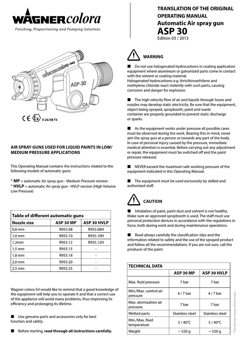
Wagner colora ASP 30 MP Operational manual

Finishing, Proportioning and Pumping Solutions
colora
TRANSLATION OF THE ORIGINAL
OPERATING MANUAL
Automatic Air spray gun
Edition 03 / 2013
ASP 30
II 2G IIB T5
Table of dierent automatic guns
Nozzle size ASP 30 MP ASP 30 HVLP
0,8 mm R955.08 R955.08H
1,0 mm R955.10 R955.10H
1,2mm R955.12 R955.12H
1,5 mm R955.15 -
1,8 mm R955.18 -
2,0 mm R955.20 -
2,5 mm R955.25 -
AIR SPRAY GUNS USED FOR LIQUID PAINTS IN LOW/
MEDIUM PRESSURE APPLICATIONS
This Operating Manual contains the instructions related to the
following models of automatic guns:
* MP = automatic Air spray gun - Medium Pressure version
* HVLP = automatic Air spray gun - HVLP version (High Volume
Low Pressure)
Use genuine parts and accessories only for best
function and safety.
Before starting, read through all instructions carefully.
WARNING
Do not use halogenated hydrocarbons in coating application
equipment where aluminium or galvanized parts come in contact
with the solvent or coating material.
Halogenated hydrocarbons e.g. thrichloroethilene and
methylene chloride react violently with such parts, causing
corrosion and danger for explosion.
The high velocity ow of air and liquids through hoses and
nozzles may develop static electricity. Be sure that the equipment,
object being sprayed, spraybooth, paint and waste
container are properly grounded to prevent static discharge
or sparks.
As the equipment works under pressure all possible cares
must be observed during the work. Bearing this in mind, never
aim the spray gun at a person or towards any part of the body.
In case of personal injury caused by the pressure, immediate
medical attention is essential. Before carrying out any adjustment
or repair, the equipment must be switched o and the paint
pressure released.
NEVER exceed the maximum safe working pressure of the
equipment indicated in this Operating Manual.
The equipment must be used exclusively by skilled and
authorized sta.
CAUTION
Inhalation of paint, paint dust and solvent is not healthy.
Make sure an approved spraybooth is used. The sta must use
personal protection devices in accordance with the regulations in
force, both during work and during maintenance operations.
Read always carefully the classication slips and the
information related to safety and the use of the sprayed product
and follow all the recommendations. If you are not sure, call the
producer of the paint.
Wagner colora Srl would like to remind that a good knowledge of
the equipment will help you to operate it and that a correct use
of the appliance will avoid many problems, thus improving its
eciency and prolonging its lifetime.
* The data may change without notice.
TECHNICAL DATA *
ASP 30 MP ASP 30 HVLP
Max. uid pressure 7 bar 7 bar
Min./Max. control air
pressure 4 / 7 bar 4 / 7 bar
Max. atomization air
pressure 7 bar 7 bar
Wetted parts Stainless steel Stainless steel
Min./Max. uid
temperature 5 / 40°C 5 / 40°C
Weight ~ 520 g ~ 520 g
All manuals and user guides at all-guides.com
all-guides.com

2
ASP 30
Operating manual
editiOn 03 /2013
SAFETY INSTRUCTIONS
For use in environments with danger of explosion.
INTRODUCTION
These safety instructions refer to the installation, use and
maintenance of the equipment for use in areas with presence of
potentially explosive atmospheres.
The equipment that these instructions refer to is equipped with
the following protections against the risk of explosion:
NOTE
These instructions must be complied with in addition to the
general safety warnings previously given.
INSTALLATION
Suitability of the equipment for the place of installation.
If it is used in areas with danger of explosion, you have to verify
that the equipment is suitable for the area’s classication and for
the characteristics of the ammable substances present on the
plant.
The essential safety requirements to prevent risk of explosion in
the classied areas are set out in European directives 94/9/EC of
23 March 1994 (regarding the equipment) and 1999/92/EC of 16
December 1999 (regarding the plants).
The criteria for classifying the areas with risk of explosion are
given in the EN 60079-10-1 standard.
The technical requisites of the electric installations in the
classied areas are given in the EN 60079-14 standard.
Based on these technical and legislative provisions, the choice of
the type of equipment must consider the following factors:
- type of plant: mine (group I), surface plants (group II)
- classication of the area: 0, 1, 2 (for which, equipment of
categories 1, 2 and 3, respectively, are suitable)
- characteristics of the ammable substances present in the form
of gas, vapours or mists
- temperature classes: T1, T2, T3, T4, T5, T6 (denes the ignition
temperature of the gases)
RATING PLATE DATA REGARDING SAFETY
In addition to the functional data, the data shown on the plate
contain the information necessary for verifying the equipment’s
suitability for a given area for its proper installation.
Mark showing compliance with the applicable European
directives.
II 2G II B T5
Mark showing compliance with directive 94/9/EC and the
other relative technical standards.
II 2 G Equipment for surface plants with presence of gas or
vapours, category 2, suitable for area 1 and (with redundancy) for
area 2.
II B Explosion group.
T5 Temperature class – Max surface temperature: 100°C
TF01PV/ATEX Code of the technical le drawn up and stored
in conformity with directive 94/9/EC
FIRE AND EXPLOSION HAZARD
EARTHING
The equipment must be put to earth by mechanic xing
(supporting bracket or uid manifold), paying attention that this
connection is not subject to loosening or unscrewing.
Avoid all electrostatic charges on connecting pipes, using a pipe in
conductive material where necessary.
EXOTHERMIC REACTIONS
Fluids incompatible with the equipment’s materials or particularly
reactive mixtures of products with several components may cause
exothermic reactions and develop dangerous temperatures or
pressure. Also check the chemical compatibility of the uid and
materials.
WARNING
Ignition temperature of the coating material.
The maximum surface temperature of the gun depends
essentially on the temperature of the coating material. The gun is
suitable for coating materials with a maximum temperature as in
the technical data table. The ignition temperature of the coating
material must be at least 15K above the working temperature.
Permissible ambient temperature: -20°C to +40°C
Contact with steel or rusty iron.
Mechanical sparks are a source of ignition , which must be
avoided (impacts, blows). Contact with steel or rusty iron, and
working with tools, particularly steel ones, is only permissible if
no explosive atmosphere is present.
Cleaning to maintain the conductive surface.
An essential part of the explosion protection is the continuous
conductivity of the gun. So clean after every use. Surface deposits,
which reduce the conductivity, have to be removed.
All manuals and user guides at all-guides.com

3
ASP 30
Ø6 G 1/4”
Ø10
38
Ø16
18
85,5
40,5 35,5
23,5
16,5
~ 148
3 x M8
~ 87,5
CA
BCA
E
D
F
C_ASP30_00002
Operating manual
editiOn 03 /2013
OPERATION
Install and operate the spray gun according to above gure.
Verify the cleanness of uid and air hoses before connection.
Check that all connections are tight.
Keep the spray gun clean and lubricate moving parts at
regular intervals.
Lubricants for surface-treatment equipment must not
contain silicon.
In the event of leakage around the paint needle, tighten the
packing screw (see F in the above gure) . After tightening,
check that the spring is still able to push forward the uid
needle.
For short standstill periods, for instance over a night, it will
suce to clean the paint nozzles and the air cap on the outside;
for longer standstill periods the gun must be ushed through
immediately with appropriate solvent.
If a two-component paint is used, however, the ushing
operation must be done no later than the pot-life time (refer
to data sheet from the paint manufacturer).
When cleaning the air cap and the paint nozzle, use a soft
brush or rag dipped in solvent. Do not place the whole gun in
solvent to avoid damaging.
Never use iron or steel wire to clean air holes and ducts in the
nozzles.
Switch the on/o pneumatic control valve in advance to
compensate, if needed, the response time of the gun.
Recommended size for control valve: 3-way, G 1/4“.
CONNECTIONS AND CONTROLS
AAtomizing air hose connection (AA).
BPaint hose connection.
CControl air hose connection (CA).
DFan width adjustment.
Clockwise turning result in a round jet and
counter-clockwise turning in a wider fan.
EPaint ow adjustment.
Clockwise turning result in a smaller
paint ow and counter-clockwise turning
increases the ow. The uid ow is
regulated in the rst instance by the choice
of paint nozzle and paint pressure.
FPaint needle packing adjusting screw.
TROUBLE SHOOTING
CAUSE SOLUTION
Fluttering paint Insucient paint in the
supply bin Rell the material bin
Blocked gun uid
passage
Clean to remove the
blockage
Worn or loose uid
nozzle Replace or tighten
Worn or loose needle
seal packing Replace or tighten
or
Paint build-up on
nozzle or un air cap
Clean uid nozzle or
air cap (do NOT use
metallic object)
Dirty or damaged uid
nozzle
Clean or replace uid
nozzle
Insucient paint
Increase
paint ow or reduce
atomizing air pressure
Too low paint viscosity Increase viscosity
Too high atomizing air
pressure
Reduce atomizing air
pressure
Too high paint viscosity Reduce viscosity
Too low atomizing air
pressure
Increase atomizing air
pressure
Dripping from uid
nozzle
Partial seizing of the
needle Lubricate needle
Too tight uid needle
packing screw Adjust
Worn uid nozzle or
needle Replace parts
Loss of paint from the
seal packing screw
(See F)
Loose uid needle
packing screw
Tighten and check
uid needle for free
movement
Dry or worn needle seal
packing Replace or lubricate
All manuals and user guides at all-guides.com

4
ASP 30
Spare parts list ASP 30
Pos. Description Q.ty Code
1 Air cap 1 See Table
2Fluid nozzle (only set available) 1 See Table
4Needle seal packing set 1 R955R.04
5 Pattern adjusting set 1 R955R.05
6Piston seal 1 R955R.06
7Piston 1 R955R.07
8 Fluid valve adjusting knob set 1 R955R.08
9 Fluid needle spring set (2 pieces) 1 R955R.09
10 Fluid needle (only set available) 1 See Table
12 Gun body 1 -
13-1 Air intake for atomization 10 mm 1 R955R.13-1
13-2 Air cylinder intake 6 mm 1 R955R.13-2
15 Cover for needle seal packing 1 R955R.15
16 Fixed bold set 2 R955R.16
20 Complete air valve set 1 R955R.20
20-1 Air valve seat 1 R955R.20-1
20-2 O-Ring 1 R955R.20-2
20-3 O-Ring 1 R955R.20-3
20-4 O-Ring 1 R955R.20-4
20-5 Holder 1 R955R.20-5
20-6 O-Ring 1 R955R.20-6
21 Fluid intake G1/4” 1 R955R.21
50 Remote air control set 1 R955R.50
= Wear parts
Air cap (pos. 1)
Description Code
Air cap G (0,8-1,0-1,2) R950R.01AP
Air cap K (1,5-1,8) R950R.01BP
Air cap R (2,0 mm) R950R.01CP
Air cap W (2,5 mm) R950R.01DP
Air cap HVLP (0,8-1,0-1,2) R950R.01HP
Fluid nozzle / needle set (pos. 2 - 10)
Description Code
Nozzle / needle set MP 0,8 mm R955R.02-10A
Nozzle / needle set MP 1,0 mm R955R.02-10B
Nozzle / needle set MP 1,2 mm R955R.02-10C
Nozzle / needle set MP 1,5 mm R955R.02-10D
Nozzle / needle set MP 1,8 mm R955R.02-10E
Nozzle / needle set MP 2,0 mm R955R.02-10F
Nozzle / needle set MP 2,5 mm R955R.02-10G
Nozzle / needle set HVLP 0,8 mm R955R.02-10H1
Nozzle / needle set HVLP 1,0 mm R955R.02-10H2
Nozzle / needle set HVLP 1,2 mm R955R.02-10H3
50
(6)
4
6
12
15
8
21
1
1
2
3
4
5
6
7
8
9
16
9
13-1 13-2
10
2
57
20-1 20-4
20
20-5
20-6
20-3
20-2
C_ASP30_00001
Pos. Codice Q.tà Descrizione Pos. Codice Q.tà Descrizione
10
12
13
14
15
16
20
20-1
20-2
20-3
20-4
20-5
20-6
21
x
x
x
x
x
x
x
-
-
-
-
-
-
-
-
-
-
-
-
-
-
-
-
1
1
1
1
1
1
1
1
1
1
1
1
1
1
1
2
Testina aria
Ugello materiale
Raccordo ingresso materiale
Ghiera premistoppa
Asta regolaz ventaglio - completa
Guarnizione pistone
Pistone
Manopola regolazione
Set molle ago
Ago vernice - completo
Corpo pistola
Raccordo aria atomizzazione 10mm
Raccordo aria controllo 6mm
Protezione premistoppa
Set vite fissaggio pistola
-
-
-
-
-
-
-
-
-
-
-
-
-
-
-
-
1
1
1
1
1
1
1
1
-
-
-
-
-
-
-
Set valvola aria completa
Sede valvola aria
O-Ring
O-Ring
O-Ring
Astuccio premistoppa (??? Verif.)
O-Ring
Raccordo ingresso materiale G1/4”
-
-
-
-
-
-
-
info@wagnercolora.com www.wagnercolora.com
Wagner colora Srl
Operating manual
editiOn 03 /2013
All manuals and user guides at all-guides.com
This manual suits for next models
1
Other Wagner colora Paint Sprayer manuals