Binks 202-755 User manual

Binks Model 202-755
HVLP GUN ASSEMBLY
Replaces
Part Sheet
77-2756R-1
Part
Sheet
77-2756R-2
READ BEFORE OPERATING
Your new High Volume, Low Pressure (HVLP) Spray gun
complies with the strict California South Coast Air Quality
Management District Rule #1162 along with Air Quality Rules
in other geographical areas. You should also know that the defi-
nition of H.V.L.P., as defined in the S.C.A.Q.M.D. Rule #1162
reads, ”High Volume Low Pressure (HVLP) spray is a coating
application system which is operated at air pressure of between
0.1 and 10 pounds per square inch gauge (PSIG).”
To maintain compliance and best results, we suggest:
1. Install air pressure test gauge (207-11799) with adapter in
gun nozzle body.
2. With an air hose connected to the assist air connection on rear
of gun, set assist air pressure to a maximum of 40 psi. Because
of the superb flow characteristics of the gun design, 40 psi
max is all that is ever required with only few exceptions.
3. Open pattern control thumbwheel all the way. Pull trigger
and observe the pressure reading of the test gauge. It should
not exceed 10 psi. Should the test gauge indicate more or
less than 10 psi, increase or decrease regulated air supply
until 10 psi is shown on test gauge while pulling trigger.
You might want to put a “landmark” on your air control
gauge for easy reference. The variables of air hose length
and regulator and gauge types sometimes require that these
adjustments become necessary.
4. Remove test gauge and adapter and install 1/16″NPT pipe
plug furnished. You are now in compliance for the criteria
HVLP. Should your local Air Quality Officer or Inspector
ever request air pressure reading, co-operate and install test
gauge and demonstrate that your nozzle pressure is 10 psi
or less.
The material transfer efficiency of your 755 HVLP Gun is
excellent but resin and catalyst pressure(s) must also be correctly
set for optimum results.
We suggest:
1. Resin pump pressure should be set as low as possible for an
acceptable spray pattern. Remember the assist air (10 psi)
plays a big part in the final spray pattern shape.
2. Select the proper spray tip for the job. A spray tip with too
small an orifice with excessive resin pump pressure would
result in poor results. It is recommended that a range of
spray tip sizes be on hand to avoid compromises. Your
spray pattern should be a soft, uniform shape without fin-
gers or tails. Resin “bounce back” should not occur.
Catalyst and catalyst atomizing pressures should also be set as
low as possible. Usually, the Catalyst Tank pressure is set at
35-40 psi. Catalyst Fan pressure should be 10 psi lower or
25-30 psi. Flowmeter (black ball) should be adjusted for
desired gel time. A good place to start would be a black ball
reading of between 60-80. Always test spray gun and gel times
on waste material until you’re ready to fabricate parts.
OPERATING INSTRUCTIONS

2
WARNING
!
In this part sheet, the words WARNING,CAUTION and NOTE are used to emphasize important safety information as follows:
CAUTION
Hazards or unsafe practices which could
result in minor personal injury, product
or property damage.
!
WARNING
Hazards or unsafe practices which could
result in severe personal injury, death or
substantial property damage.
!
NOTE
Important installation, operation or
maintenance information.
Read the following warnings before using this equipment.
FOR FURTHER SAFETY INFORMATION REGARDING BINKS AND DEVILBISS EQUIPMENT,
SEE THE GENERAL EQUIPMENT SAFETY BOOKLET (77-5300).
READ THE MANUAL
Before operating finishing equipment, read and
understand all safety, operation and maintenance
information provided in the operation manual.
PLURAL COMPONENT MATERIALS HAZARD
Because of the vast number of chemicals that could
be used and their varying chemical reactions, the
buyer and user of this equipment must determine
all facts relating to the materials used, including
any of the potential hazards involved.
NOISE HAZARD
You may be injured by loud noise. Hearing protection
may be required when using this equipment.
FIRE AND EXPLOSION HAZARD
Improper equipment grounding, poor ventilation,
open flame or sparks can cause hazardous
conditions and result in fire or explosion and
serious injury.
PINCH POINT HAZARD
Moving parts can crush and cut. Pinch points are
basically any areas where there are moving parts.
KNOW WHERE AND HOW TO SHUT OFF THE
EQUIPMENT IN CASE OF AN EMERGENCY
PRESSURE RELIEF PROCEDURE
Always follow the pressure relief procedure in the
equipment instruction manual.
WEAR SAFETY GLASSES
Failure to wear safety glasses with side shields
could result in serious eye injury or blindness.
DE-ENERGIZE, DEPRESSURIZE, DISCONNECT
AND LOCK OUT ALL POWER SOURCES DURING
MAINTENANCE
Failure to De-energize, disconnect and lock out
all power supplies before performing equipment
maintenance could cause serious injury or death.
OPERATOR TRAINING
All personnel must be trained before operating
finishing equipment.
EQUIPMENT MISUSE HAZARD
Equipment misuse can cause the equipment to
rupture, malfunction, or start unexpectedly and
result in serious injury.
KEEP EQUIPMENT GUARDS IN PLACE
Do not operate the equipment if the safety
devices have been removed.
HIGH PRESSURE CONSIDERATION
High pressure can cause serious injury. Relieve all
pressure before servicing. Spray from the spray
gun, hose leaks, or ruptured components can
inject fluid into your body and cause extremely
serious injury.

3
Do not handle or use until safety precautions
concerning Methyl Ethyl Ketone Peroxides in
the Manufacturer’s literature have been read
and understood.
Contact with foreign materials, especially
strong mineral acids, metals (including certain
equipment and containers) or metal salts, or
exposure to heat above 135° F (57° C) may
lead to violent decomposition, releasing
flammable vapors which may self-ignite.
Do not get into eyes or on skin or clothing.
Wear eye and skin protection when handling.
Avoid breathing mist. Use with adequate
ventilation. Store only it in the original
closed container. Wash hands thoroughly
after handling. Protect from direct sunlight,
heat, sparks and other sources of ignition.
Prevent contamination with foreign materials.
Do not add to hot materials.
To maintain the chemical activity store below
100° F (38° C).
In case of fire, use water spray, foam or dry
chemical.
In case of spill or leak, absorb or blend with
inert, non-combustible material. Put in suitable
container. Dispose of immediately in
accordance with federal, state and local
regulations.
Do not reuse container as some of the original
hazardous contents may still be present.
Follow the above precautions in handling.
HALOGENATED HYDROCARBON
SOLVENTS CAN CAUSE AN EXPLOSION
WHEN IN CONTACT WITH ALUMINUM
COMPONENTS OF A PRESSURIZED OR
CLOSED FLUID SYSTEM (PUMPS,
HEATERS, FILTERS, etc.)
The same possibility of an explosion is possible
with the galvanized coatings in pressure tanks.
The possibility of a non-flammable explosion
increases greatly at high operating temperatures.
The explosion could be of sufficient strength to
cause bodily injury, death, and substantial
property damage.
Cleaning agents, coatings, or adhesives may
contain HALOGENATED HYDROCARBON
SOLVENTS. CHECK WITH YOUR SOLVENT
AND PAINT SUPPLIER.
If you are now using a Halogenated Hydrocarbon
Solvent in a pressurized fluid system with
aluminum components or galvanized wetted
parts, the following steps should be taken
immediately:
1. Remove all pressure; drain and disconnect
the entire system.
2. Inspect and replace all corroded parts.
3. Contact your solvent supplier for a
NON-HALOGENATED SOLVENT to
flush and clean the system of all residues.
HALOGENATED Solvents are defined as any
hydrocarbon solvent containing any of the
following elements:
CHLORINE “CHLORO” (Cl)
BROMINE “BROMO” (Br)
FLUORINE “FLUORO” (F)
IODINE “IODO” (I)
Of those listed, the Chlorinated Solvents will
most likely be the type used as a cleaning agent
or solvent in an adhesive or coating. The most
common are:
METHYLENE CHLORIDE
1,1,1, TRICHLORETHANE
PERCHLORETHYLENE
Although stabilizers have been added to some
of the solvents to reduce their corrosive effect,
we are aware of none that will prevent these
solvents from reacting under all conditions
with aluminum components or galvanized
coatings.
Previous use of the solvents under pressurized
conditions, without incident, does not necessarily
indicate that it can be considered safe.
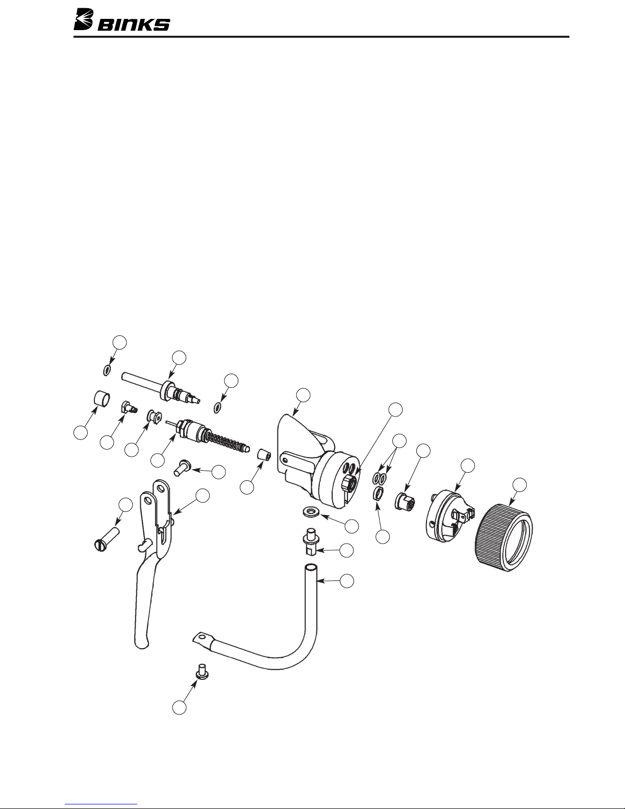
Model 202-755 GUN is constructed with
components of aluminum alloy
and SHOULD NOT be used with any
Halogenated Hydrocarbon solvents.
WARNING
!
WARNING
!
When using Binks equipment with
Methyl Ethyl Ketone Peroxide in Plasticizer
OBSERVE the following precautions
CORROSIVE TO THE EYES – MAY CAUSE BLINDNESS.
MAY BE FATAL IF SWALLOWED. STRONG IRRITANT.
CONTAMINATION OR HEAT MAY LEAD TO FIRE OR
EXPLOSIVE DECOMPOSITION. COMBUSTIBLE.
READ & UNDERSTAND THE MATERIAL SAFETY DATA SHEET FROM
MATERIAL SUPPLIER
FIRST AID
EYES
Wash immediately (seconds count) with
water and continue washing for at least
15 minutes. Obtain medical attention.
SKIN
Wash with soap and water. Remove
contaminated clothes and shoes and again
wash thoroughly with soap and water.
SWALLOWING
Administer large quantities of milk or
water. Obtain immediate medical attention
for lavage.

21
10
12
11
13
14
15
49
23 24 25
22
CONTINUED ON
NEXT PAGE
4
Binks MODEL 202-755 HVLP GUN
4237-89▲O-RING .................................................. 3
9207-11365 AIR VALVE ASSEMBLY.......................... 1
10 207-10101 DOWEL ................................................ 1
11 207-11768 HANDLE ................................................ 1
12 207-11792 CURB SCREW ........................................ 1
13 71-28 DM NIPPLE............................................ 1
14 237-68▲O-RING .................................................. 1
15 207-11258 MATERIAL FEED TUBE (1/4") .............. 1
ITEM PART
NO. NO. DESCRIPTION QTY.
21 207-10548 VALVE ASSEMBLY ................................ 1
22 237-12 ROLL PIN .............................................. 1
23 207-10108 SAFETY SPRING .................................... 1
24 207-10109 SAFETY PAD ........................................ 1
25 207-10107 SAFETY PIN .......................................... 1
ITEM PART
NO. NO. DESCRIPTION QTY.
▲Items are included in Repair Kit 207-11796. Please order separately.
PARTS LIST
When ordering, please specify Part No.
CONTINUED ON NEXT PAGE

Binks MODEL 202-755 HVLP GUN
5
29 30 31
32
33
5
7
8
7
6
6a
43
2
1
27
28
26
37
36
35
34
1207-11269 NOZZLE RETAINING RING .................... 1
2207-11763-1 CATALYST NOZZLE KIT - 25° ................ 1
3— TC TIP ....................................................REF
4237-89▲O-RING .................................................. 3
5207-11392▲SEAL ...................................................... 1
6207-11328 NOZZLE ASSEMBLY .............................. 1
6a 207-11264 NOZZLE INSERT ....................................REF
720-2198 ▲O-RING.................................................. 2
8207-11794 AIR VALVE ASSEMBLY.......................... 1
26 207-10355 TRIGGER SCREW RETAINER ................ 1
27 237-654 PAN HEAD SCREW .............................. 1
28 207-11497 TRIGGER................................................ 1
29 207-10116 SLEEVE .................................................. 1
ITEM PART
NO. NO. DESCRIPTION QTY.
30 207-10192 RESIN NEEDLE COLLET ........................ 1
31 207-10191 RESIN NEEDLE HOLDER ...................... 1
32 207-11364 MATERIAL VALVE ASSEMBLY .............. 1
33 207-10096▲RESIN NEEDLE SEAT ............................ 1
34 237-152 WASHER................................................ 1
35 207-10098 TRIGGER GUARD STUD........................ 1
36 207-10100-1 TRIGGER GUARD .................................. 1
37 237-212 PAN HEAD SCREW .............................. 1
38 207-11340 SHUT DOWN PLUG (NOT SHOWN) .... 1
39 207-11796 REPAIR KIT (NOT SHOWN) .................. 1
40 207-11799 TEST GAUGE KIT .................................. 1
41 237-707 WET FILM GAUGE ................................ 1
Also included loose in box:
42 207-10432 HARD SEAT SPRING.............................. 1
43 207-10424 HARD SEAT .......................................... 1
44 207-10423 HARD SEAT RESIN NEEDLE .................. 1
ITEM PART
NO. NO. DESCRIPTION QTY.
▲Items are included in Repair Kit 207-11796. Please order separately.
PARTS LIST
When ordering, please specify Part No.

6
207-11763-1 CATALYST NOZZLE KIT (25°)
2a 207-11761-1 CATALYST NOZZLE – 25° ...................... 1
2b 237-708▲O-RING .................................................. 1
2c 237-709▲O-RING .................................................. 1
2d 207-11762 TRANSFER DISC ASSEMBLY.................. 1
▲Items are included in Repair Kit 207-11796. Please order separately.
ITEM PART
NO. NO. DESCRIPTION QTY.
PARTS LIST
When ordering, please specify Part No.
ITEM 2 ON MAIN EXPLODED VIEW
2d
2c
2b
2a
207-11365 AIR VALVE ASSEMBLY
9a 207-11551 SCREW .................................................. 1
9b 54-747 PACKING .............................................. 1
9c 207-11548 VALVE BODY ........................................ 1
9d 207-11547▲SEAL ...................................................... 1
9e 20-3236▲O-RING.................................................. 1
9f 207-12141 PUSHROD.............................................. 1
9g 207-11329 SPRING .................................................. 1
▲Items are included in Repair Kit 207-11796. Please order separately.
ITEM PART
NO. NO. DESCRIPTION QTY.
PARTS LIST
When ordering, please specify Part No.
ITEM 9 ON MAIN EXPLODED VIEW
9g
9f
9e 9d
9c
9b 9a
207-10548 VALVE ASSEMBLY
21a 207-10252 VALVE CAP............................................ 1
21b 20-3562▲O-RING .................................................. 2
21c 207-10286 SPACER.................................................. 1
21d 207-10088 VALVE BODY ........................................ 1
21e 237-92 O-RING.................................................. 1
21f 207-10284▲VALVE BUSHING .................................. 1
21g 207-10521 PUSH ROD ............................................ 1
▲Items are included in Repair Kit 207-11796. Please order separately.
ITEM PART
NO. NO. DESCRIPTION QTY.
PARTS LIST
When ordering, please specify Part No.
ITEM 21 ON MAIN EXPLODED VIEW
21g
21f 21e
21d 21b
21c
21b
21a

207-11364 MATERIAL VALVE ASSEMBLY
7
PART NO. DESCRIPTION ID No.
211-91525 GEL COAT TIP .015 X 25° 1525
211-91540 GEL COAT TIP .015 X 40° 1540
211-91825 GEL COAT TIP .018 X 25° 1825
211-91840 GEL COAT TIP .018 X 40° 1840
211-91850 GEL COAT TIP .018 X 50° 1850
211-92125 GEL COAT TIP .021 X 25° 2125
211-92140 GEL COAT TIP .021 X 40° 2140
211-92340 GEL COAT TIP .023 X 40° 2340
211-92350 GEL COAT TIP .023 X 50° 2350
211-92640 GEL COAT TIP .026 X 40° 2640
211-93140 GEL COAT TIP .031 X 40° 3140
211-93625 GEL COAT TIP .036 X 25° 3625
211-93640 GEL COAT TIP .036 X 40° 3640
211-94325 GEL COAT TIP .043 X 25° 4325
211-94340 GEL COAT TIP .043 X 40° 4340
211-95225 GEL COAT TIP .052 X 25° 5225
211-95240 GEL COAT TIP .052 X 40° 5240
211-95725 GEL COAT TIP .057 X 25° 5725
211-96225 GEL COAT TIP .062 X 25° 6225
202-755 HVLP GUN TIP SELECTION CHART
207-11796 REPAIR KIT
32a 207-11345 RESIN NEEDLE ...................................... 1
32b 207-11330 SPRING .................................................. 1
32c 237-69▲O-RING .................................................. 1
32d 207-10093 NEEDLE FITTING .................................. 1
32e 207-10095▲NEEDLE PACKING ................................ 1
32f 207-10094 PACKING NUT ...................................... 1
▲Items are included in Repair Kit 207-11796. Please order separately.
2b 237-708 O-RING.................................................. 1
2c 237-709 O-RING.................................................. 1
4237-89 O-RING.................................................. 3
5207-11392 SEAL ...................................................... 1
720-2198 O-RING.................................................. 2
9d 207-11547 SEAL ...................................................... 2
9e 20-3236 O-RING .................................................. 2
14 237-68 O-RING .................................................. 1
19b 207-10533 RETAINING RING .................................. 1
19c 237-87 O-RING.................................................. 1
19d 20-2183 BALL...................................................... 1
21b 20-3562 O-RING.................................................. 2
21f 207-10284 VALVE BUSHING .................................. 1
32c 237-69 O-RING.................................................. 1
32e 207-10095 NEEDLE PACKING ................................ 1
33 207-10096 RESIN NEEDLE SEAT ............................ 1
237-455 BRUSH .................................................. 1
237-456 PACKING TOOL .................................... 1
ITEM PART
NO. NO. DESCRIPTION QTY.
ITEM PART
NO. NO. DESCRIPTION QTY.
ITEM PART
NO. NO. DESCRIPTION QTY.
PARTS LIST
When ordering, please specify Part No.
ITEM 32 ON MAIN EXPLODED VIEW
32f 32e 32d 32c
32b
32a
NOTE
For hard needle/spring: Replace item 32a with
207-10423 hard needle and replace item 32b
with 207-10432 hard spring.

1/08 © 2008 Inc. All rights reserved. Printed in U.S.A.
Industrial Finishing
Binks has authorized distributors throughout the world. For technical
assistance or the distributor nearest you, see listing below.
U.S./Canada Technical Service Office:
195 Internationale Blvd., Glendale Heights, IL 60139
Toll-Free Telephone: 1-888-992-4657 (U.S.A. and Canada only)
Toll-Free Fax: 1-888-246-5732
Binks Worldwide Sales and Service Listing: www.binks.com
WARRANTY
This product is covered by Binks’ 1 Year Limited Warranty.
77-2756R-2 Revisions: (P4) Updated exploded view and Parts List; (P6) Removed
207-10651; (P7) Edited 207-11796 Repair Kit parts List, edited 202-755 HVLP Gun
Tip Selection Chart.
TROUBLESHOOTING
Material leak at Nozzle. Resin Valve Seat damaged. Replace Seat.
Gun won’t shut off. Packing nut too tight to allow needle Loosen packing nut slightly
to return to seat. and lubricate.
Packing worn and material leakage Clean assembly and replace
in valve assembly holds needle open. packing. Lubricate.
Material leaks at back of Packing nut too loose. Tighten packing nut slightly.
material valve. Packing worn. Clean assembly and replace
packing.
No material when trigger Out of material. Check supply.
is pulled. Pump filter clogged. Clean filter.
Pump by-pass valve open. Close valve.
Plugged tip. Remove and clean carefully
with wooden toothpick.
Needle valve/stem broken. Replace needle valve/stem.
Loose collet and holder. Adjust and tighten nut.
Air leaks at catalyst Valve cap too tight to allow needle to close. Loosen valve cap, lubricate.
nozzle when not in use. Valve seat worn. Replace seat.
Catalyst drippage at Valve cap too tight or dirty. Clean and loosen valve cap.
nozzle when not in use. Valve seat worn. Replace valve seat.
Valve o-ring damaged. Replace o-ring.
Catalyst drippage at Nozzle o-rings damaged. Replace o-rings.
nozzle when in use. Insufficient fan air. Increase catalyst Fan air.
Burst of catalyst. Valve o-ring damaged. Replace o-ring.
Inner catalyst line damaged. Replace inner line.
Binks MODEL 202-755 HVLP GUN
Table of contents
Other Binks Paint Sprayer manuals

Binks
Binks AA4400M User manual

Binks
Binks 59-10001 A User manual

Binks
Binks MX1212 User manual

Binks
Binks 570 User manual

Binks
Binks HAP 50 Series User manual

Binks
Binks TROPHY SERIES User manual

Binks
Binks 2100 SERIES User manual

Binks
Binks 2100 SERIES User manual

Binks
Binks AA1600M User manual

Binks
Binks 2100 gw User manual