WAGNER HC950 User manual

Ausgabe 6 / 2014 0528 940G
Edition
Edizione
I
GB F
D
Betriebsanleitung
Operating manual ...........p. 24
Mode d’emploi.................p. 48
Istruzioni per l’uso...........p. 72
Airless Hochdruck-Spritzgerät
Airless high-pressure spraying unit
Groupe de projection à haute pression
Impianto per la verniciatura a spruzzo ad alta pressione Airless
HC 950 230V HC 970 400V
HC 950 SSP
230V HC 950 SSP
HC 970 SSP
HC 950
HC 970
HC 970 SSP
400V
HC950 • HC950 SSP
HC970 • HC970 SSP

24
GB
Warning!
Attention: Danger of injury by injection!
Airless units develop extremely high spraying pressures.
Be safety conscious!
1
2
3
Never put your ngers, hands or any other parts of the body into
the spray jet!
Never point the spray gun at yourself, other persons or animals.
Never use the spray gun without safety guard.
Do not treat a spraying injury as a harmless cut. In case of injury
to the skin through coating materials or solvents, consult a doctor
immediately for quick and expert treatment. Inform the doctor
about the coating material or solvent used.
The operating instructions state that the following points must
always be observed before starting up:
1. Faulty units must not be used.
3. Ensure that the unit is properly earthed.
4. Check allowable operating pressure of high-pressure hose and
spray gun.
5. Check all connections for leaks.
The instructions regarding regular cleaning and maintenance of
the unit must be strictly observed.
Before any work is done on the unit or for every break in work the
following rules must be observed:
1. Release the pressure from spray gun and hose.
3. Switch o unit.
Original Operating Manual

GB
Contents
Contents
Page
1. Safety regulations for Airless spraying....................................26
............................................................26
1.2 Electrical safety.......................................................................................
1.3 Gasoline engine safety........................................................................28
1.4 Setting up on uneven surfaces.........................................................28
2. General view of application...........................................................29
2.1 Application ..............................................................................................29
2.2 Coating materials ..................................................................................29
3. Description of unit..............................................................................29
3.1 Airless process........................................................................................29
3.2 Functioning of the unit .......................................................................29
3.3 Illustration legend for gasoline HC units ......................................30
3.4 Illustration of gasoline HC units.......................................................30
3.5 Illustration legend for electric HC units.........................................31
3.6 Illustration of electric HC units .........................................................31
..............................................32
................................................33
..................................................................................................34
..............................................................................34
3.11 Crane transport......................................................................................34
4. Starting operation..............................................................................35
4.1 Changing the material feed pump position................................35
4.2 High-pressure hose, spray gun and separating oil ...................36
4.3 Gasoline engine (gas units only)......................................................36
4.4 Connection to the mains (electric units only).............................36
4.5 Flushing preserving uid during initial start-up........................36
..............
5. Spraying technique ...........................................................................
6. Handling the high-pressure hose ...............................................
7. Interruption of work..........................................................................
8. Cleaning the unit (shutting down) .............................................38
8.1 Cleaning the unit from the outside ................................................38
8.2 Cleaning the high-pressure lter.....................................................38
8.3 Cleaning Airless spray gun.................................................................39
Page
9. Remedy in case of faults..................................................................40
9.1 Gasoline engine.....................................................................................40
9.2 Electric motor .........................................................................................40
9.3 Hydraulic motor.....................................................................................40
9.4 Material feed pump..............................................................................41
10. Servicing..................................................................................................42
10.1 General servicing...................................................................................42
10.2 Checking the oil level in the hydraulic oil tank ..........................42
...................42
10.4 High-pressure hose...............................................................................42
11. Appendix.................................................................................................43
11.1 Selection of tip .......................................................................................43
11.2 Servicing and cleaning of Airless hard-metal tips ....................43
11.3 Spray gun accessories..........................................................................43
11.4 Airless tip table................................................................................ 44/45
....................................................................................46
Sales and service companies.......................................................................
Accessories and spare parts ........................................................................96
Accessories for HC units I ..........................................................................
Accessories for HC units II ......................................................................... 98/99
Spare parts list for the main assembly............................................. 100/101
Spare parts list for the cart assembly ............................................... 102/103
Spare parts list for the hydraulic system......................................... 104/105
Spare parts list for the hydraulic motor ..........................................
Spare parts list for the uid section.................................................. 108/109
Spare parts list for the shovel valve
...................................................................... 110/111
Spare parts list for the high-pressure lter .................................... 112/113
Spare parts list for electric convertokit (230V / 400V)..........................114
Spare parts list for gas convertokit .............................................................116
Spare parts list for belt guard assembly....................................................
Spare parts list for bleed valve .....................................................................118
Electrical schematic HC950 • HC970 ......................................................119
Important notes on product liability ....................................................121
3+2 years guarantee for professional nishing ..............................121

26
GB
Safety precautions
1. Safety regulations for Airless spraying
1.1 Explanation of symbols used
of the following symbols, pay particular attention and make certain
to heed the safeguard.
This symbol indicates a potential hazard that
may cause serious injury or loss of life. Important
safety information will follow.
Attention
This symbol indicates a potential hazard to you
or to the equipment. Important information that
tells how to prevent damage to the equipment or
how to avoid causes of minor injuries will follow.
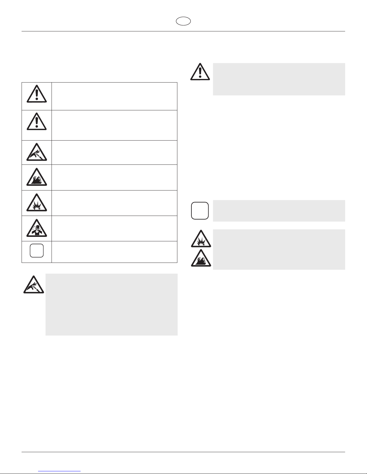
Danger of skin injection
Danger of fire from solvent and paint fumes
Danger of explosion from solvent, paint fumes
and incompatible materials
Danger of injury from inhalation of harmful
vapors
i
Notes give important information which should
be given special attention.
HAZARD: INJECTION INJURY
A high pressure stream produced by this equipment
can pierce the skin and underlying tissues, leading to
serious injury and possible amputation.
Do not treat a spraying injury as a harmless cut. In
case of injury to the skin through coating materials
or solvents, consult a doctor immediately for quick
and expert treatment. Inform the doctor about the
coating material or solvent used.
PREVENTION:
provide protection against an injection injury.
release all pressure before servicing, cleaning the tip guard,
changing tips, or leaving unattended. Pressure will not be
or pressure bleed valve must be turned to their appropriate
positions to relieve system pressure.
provides some protection but is mainly a warning device.
system.
trigger guard in place.
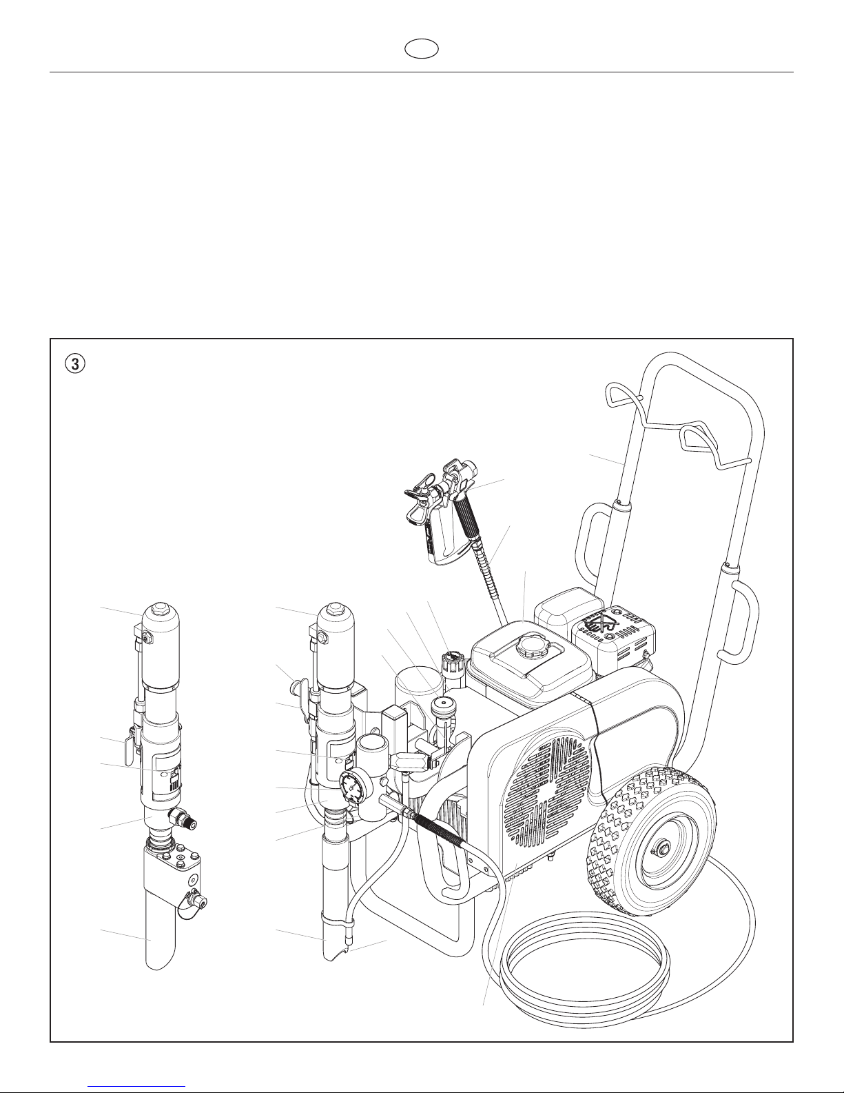
HAZARD
: HIGH PRESSURE HOSE
The paint hose can develop leaks from wear, kinking
and abuse. A leak can inject material into the skin.
Inspect the hose before each use.
PREVENTION:
are used.
about 20 cm.
sharp objects and edges.
wet cloth to wipe down the outside of the hose.
cannot be tripped over.
i
Only use WAGNER original-high-pressure hoses in
order to ensure functionality, safety and durability.
HAZARD: EXPLOSION OR FIRE
Solvent and paint fumes can explode or ignite.
Severe injury and/or property damage can occur.
PREVENTION:
Flashpoint is the temperature at which a uid can produce
enough vapors to ignite.
keep the air within the spray area free from accumulation of
ammable vapors.
electrical appliances, ames, pilot lights, hot objects, and
sparks from connecting and disconnecting power cords or
working light switches.
well ventilated area (add more hose if necessary). Flammable
vapors are often heavier than air. Floor area must be
that emit sparks and can ignite vapors.
be properly grounded to prevent static sparks.
must be earthed through hose connections.
units only).
pressure, with spray tip removed. Hold gun rmly against side
of container to ground container and prevent static sparks.

GB
Safety precautions
sheet and technical information to ensure safe use.
never be sprayed or pumped back into a container with a
HAZARD: HAZARDOUS VAPORS
Paints, solvents, and other materials can be harmful
if inhaled or come in contact with body. Vapors can
cause severe nausea, fainting, or poisoning.
PREVENTION:
instructions supplied with the mask to be sure it will provide
the necessary protection.
vapors must be observed.
regulations of the manufacturer concerning coating materials,
solvents and cleaning agents in preparation, processing and
cleaning units.
HAZARD: GENERAL
This product can cause severe injury or property
damage.
PREVENTION:
governing ventilation, re prevention, and operation.
particularly powerful when the tip has been removed and
a high pressure has been set on the airless pump. When
cleaning without a spray tip, set the pressure control knob to
the lowest pressure.
risks and liabilities when using parts that do not meet the
minimum specications and safety devices of the pump
manufacturer.
safe handling of paint and solvents.
slip hazard.
85 dB(A).
children or anyone not familiar with the operation of airless
disposed of in an environmentally friendly way.
1.2 Electric Safety
Electric models must be earthed. In the event of an electrical short
circuit, earthing reduces the risk of electric shock by providing an
a cord having an earthing wire with an appropriate earthing plug.
Connection to the mains only through a special feed point, e.g.
DANGER — Work or repairs at the electrical
equipment may only be carried out by a skilled
electrician. No liability is assumed for incorrect
installation. Switch the unit o. Before all repair
work, unplug the power plug from the outlet.
Danger of short-circuits caused by water ingressing into the electrical
pressure steam cleaners.
Work or repairs at the electrical equipment:
assumed for incorrect installation.

28
GB
Safety precautions
1.3 Gasoline Engine Safety
Always place sprayer outside of structure in fresh
air. Keep all solvents away from engine exhaust.
Never ll fuel tank with a running or hot engine.
Hot surface can ignite spilled fuel. Always attach
ground wire from pump to a grounded object.
Refer to engine owner’s manual for complete safety
information.
1. Gas engines are designed to give safe and dependable service
if operated according to instructions. Read and understand
the engine. Failure to do so could result in personal injury or
keep the engine at least 1 meter (3 feet) away from buildings
ammable objects close to the engine.
3. People who are not operating the device must stay away from
the area of operation due to a possibility of burns from hot
may be used to operate.
engine without proper instructions.
certain conditions.
6. Refuel in a well-ventilated area with the engine stopped. Do
not smoke or allow ames or sparks in the refueling area or
where gasoline is stored.
tank cap is closed properly and securely.
8. Be careful not to spill fuel when refueling. Fuel vapor or
spilled fuel may ignite. If any fuel is spilled, make sure the area
is dry before starting the engine.
cause loss of consciousness and may lead to death.
hot for a while after stopping the engine. Be careful not to
hazards, let the engine cool before transporting it or storing it
indoors.
DO NOT use this equipment to spray water or acid.
1.4 Setting up on uneven surfaces
away.

GB
General view of application Description of unit
2. General view of application
2.1 Application
Priming and nal coating of large areas, sealing, impregnation,
construction sanitation, façade protection and renovation, rust
protection and building protection, roof coating, roof sealing,
concrete sanitation, as well as heavy corrosion protection.
Examples of objects to be sprayed
Large-scale construction sites, underground construction, cooling
towers, bridges, sewage treatment plants and terraces.
2.2 Coating materials
Processible coating materials
i
Pay attention to the Airless quality of the coating
materials to be processed.
zinc dust and micaceous iron ore paints, Airless spray primer,
sprayable glue, anti-corrosive agents, thick coating materials and
bitumen-like coating materials.
approval.
HC 950-SSP
With suitable accessories, especially for working with airless spray
HC 970-SSP
Filtering
In spite of the high-pressure lter, ltering of the coating material is
ller).
Stir coating material before commencement of work.
iMake sure when stirring with motor-driven agitators
that no air bubbles are stirred in. Air bubbles disturb
when spraying and can, in fact, lead to interruption
of operation.
Viscosity
It is possible to work with high-viscosity coating materials with the
devices.
If highly viscous coating materials cannot be sucked up, they must be
Two-component coating material
this time rinse through and clean the unit meticulously with the
appropriate cleaning agents.
Coating materials with sharp-edged additional materials
appreciably through this.
3. Description of unit
3.1 Airless process
material for large areas and a high consumption of material.
A piston pump takes in the coating material by suction and conveys it
pressure has the eect of micro ne atomisation of the coating
material.
As no air is used in this process, it is described as an AIRLESS process.
cloudless operation and a smooth, bubble-free surface. As well as
these, the advantages of the speed of work and convenience must be
mentioned.
3.2 Functioning of the unit
construction for better understanding of the function.
either a gasoline engine or electric motor.
hydraulic pump (3) by means of a V-belt which is under the belt cover
(2). Hydraulic oil ows to the hydraulic motor (4) and then moves the
piston up and down in the material feed pump (5).
viscosity coating materials.
downward.
the tip it atomises.
pressure of the coating material.
1
2
6
73
5
4

30
GB
Description of unit
3.3 Illustration legend for gasoline HC units
1 Spray gun
2 High-pressure hose
3 Gasoline engine
5 V-belt under the belt cover
6 Return hose
8 High-pressure lter
11 Pressure gauge
wear and tear of the packings)
13 Ball valve: horizontal position – hydraulic motor switched o
vertical position – hydraulic motor switched on
14 Handle for swiveling the material feed pump
15 Hydraulic motor
k
p
18 Pressure control knob
3.4 Illustration of gasoline HC units
2
4
3
5
77
13
15
13
15
16
1817 19
14
11
12
12
8
9
10
1
6

GB
Description of unit
3.5 Illustration legend for electric HC units
1 Spray gun
2 High-pressure hose
3 Electric motor
5 Control lamp that shows unit operational —
HC 950, HC 950-SSP
6 Power cord
8 Control lamp that shows unit operational —
10 V-belt under the belt cover
11 Return hose
12 Suction tube
13 High-pressure lter
16 Pressure gauge
wear and tear of the packings)
18 Ball valve: horizontal position – hydraulic motor switched o
vertical position – hydraulic motor switched on
19 Handle for swiveling the material feed pump
20 Hydraulic motor
k
p
22 Hydraulic oil pump
23 Pressure control knob
3.6 Illustration of electric HC units
2
89
1
3
21
2322 24
12
18
20
19
16
17
13
14
11
6
7
10
12
18
20
17
15
45

32
GB
Description of unit
HC 950
(0528500) HC 950-SSP
(0528502) HC 970
(0528508) HC 970-SSP
(0528506)
Gasoline engine, power
4.1 kW: R R
6 kW: R R
Max. operating pressure
25 MPa (250 bar): RRRR
Max. volume ow
8 l/min: R R
12 l/min: R R
Volume ow at 12 MPa (120) bar
R R
11 l/min: R R
Max. size of tip with a spray gun
0.052 inch – 1.30 mm: R R
0.056 inch – 1.42 mm: R R
Fluid outlet tting
3/8 inch – 9.5 mm: R
RRR
Max. temperature of the coating material
RRRR
Max. Viscosity
50.000 mPa·s: R R
65.000 mPa·s: R R
Filter insert (standard equipment)
0 Mesh: RRRR
Weight
R R
88 kg R R
Hydraulic oil lling quantity
RRRR
Max. tire pressure
0.2 MPa (2 bar): RRRR
Special high-pressure hose
R
RRR
Hose whip
RRR
Dimensions L x W x H
R R
R R
Max.sound pressure level:
92 dB (A)* R R
98 dB (A)* R R
* Place of measurement: 1 m distance from unit and 1.60 m above reverberant oor, 120 bar (12 MPa) operating pressure.
3.7 Technical data for gasoline HC units

GB
Description of unit
HC 950
(0528501) HC 950-SSP
(0528503) HC 970
(0528509) HC 970-SSP
(0528507)
Voltage
230 V~, 50 Hz: R R
400 V, 50 Hz, V3~:R R
Fuse protection
16 A: R R R R
Power cord
– 6 m: R R
– 6 m: R R
Capacity
3.6 kW: R R
5.5 kW: R R
Max operating pressure
25 MPa (250 bar): RRRR
Maximum volume ow
6.6 l/min: R R
10 l/min: R R
Volume ow at 12 MPa (120 bar)
5.2 l/min: R R
10 l/min: R R
Max. size of tip with a spray gun
0.052 inch – 1.30 mm: R R
0.056 inch – 1.42 mm: R R
Fluid outlet tting
3/8 inch – 9.5 mm: R
RRR
Max. temperature of the coating material
RRRR
Max. Viscosity
50.000 mPa·s: R R
65.000 mPa·s: R R
Filter insert (standard equipment)
0 Mesh: RRRR
Weight:
83 kg R
84.5 kg R
100 kg R
103 kg R
Hydraulic oil lling quantity
RRRR
Max. tire pressure
0.2 MPa (2 bar): RRRR
Special high-pressure hose
R
RRR
Hose whip
RRR
Dimensions L x W x H
R R
R R
Max. sound pressure level:
80 dB (A)* R R
88 dB (A)* R R
* Place of measurement: 1 m distance from unit and 1.60 m above reverberant oor, 12 MPa (120 bar) operating pressure.
3.8 Technical data for electric HC units

34
GB
Description of unit
Operating Temperature
Relative Humidity
Measures shall be taken by the Purchaser to avoid the harmful eects
of occasional condensation.
Altitude
level.
Transportation and Storage
It has been packaged to prevent damage from the eects of normal
humidity, vibration and shock.
3.9 Transport
Attention
Do not lift by cart handle when loading or unloading.
Device is very heavy. Three-person lift is required.
Handle
Pull out the handle (g. 5, item 1) until it will come no further. Push in
the snap buttons (2) on the sides of the handle and insert the handle.
1
2
2
3.10 Transport in vehicle
Push locking pin (g. 6, item 1) in the swivel mechanism (2) for the
material feed pump (3) and swivel it to a horizontal position. Ensure
that the locking pin locks.
Roll the high-pressure hose over the hose rack on the handle.
Secure the unit with a suitable fastening.
3
2
1
3.11 Crane transport

2. Operating position I (g. 10)
Swiveling the material feed pump to a vertical position allows
the material feed pump to be immersed in the coating material
container.
3. Operating position II (g. 11)
container suction system (accessory). In this position, there is open
space under the material feed pump.
4. Starting operation
4.1 Changing the material feed pump position
Be careful, as the moving parts of the swivel
mechanism can crush ngers and feet.
1. Grip handle (g. 8, item 1) with one hand.
2. Push locking pin (2) with the other hand.
3. Swivel material feed pump up or down to the desired
position, until the locking pin (2) locks into the new position.
1
2
1. Transport position (g. 9)
position.
Swiveling the material feed pump to a horizontal position also allows
removal of the pump from the coating material container.
Ensure that the locking pin locks.
GB
Starting operation

36
GB
Starting operation
4.2 High-pressure hose, spray gun and separating
oil
1. Screw the high-pressure hose (g. 12, item 1) onto the hose
connection (2).
into the high-pressure hose.
Screw on hose whip (4).
3. Screw connection socket (5) to the spray gun (6).
4. Screw spray gun with selected tip to the high-pressure hose or
hose whip (4), depending on the model.
the model, at the hose whip to prevent coating material from
leaking.
2
1
5
6
4
1
3
6. Fill in EasyGlide (g. 13). Do not ll in too much separating
oil, i.e. ensure that no separating oil drips into the coating
material container.
Attention
EasyGlide prevents increased wear and tear to the
packings.
4.3 Gasoline engine (gas units only)
1. Fill in the supplied engine oil.
when the oil level is too low.
instructions.
2. Fill the gasoline tank.
For information on the gasoline please refer to the engine
instructions.
4.4 Connection to the mains (electric units only)
Attention
The connection must take place through a properly
earthed two-pole and earth socket outlet.
Before connecting the unit to the mains supply, make sure that the
been connected.
4.5 Flushing preserving uid during initial
start-up
1. Push locking pin (g. 14, item 1) and swivel material feed
pump to a container with suitable cleaning agent.
the left (pressure reduction) until it stops.
k
Circulation).
4. Start the engine or turn on the electric motor.
iThe direction of the rotation of the pulley must
correspond to the arrow (4) on the belt cover. If the
belt is running opposite the direction of the arrow:
Switch unit to “O” (OFF). Unplug power plug and
turn the polarity changer (5) in the power plug by
180º with a screwdriver. Plug in power plug again.
5. Move the hydraulic ball valve (6) on the material feed pump
motor.
Hydraulic oil ows to the hydraulic motor of the material feed
pump.
pspray).
8. Pull the trigger of the spray gun.
9. Spray the cleaning agent from the unit into an open collecting
container.

GB
Starting operation Interruption of work
2
1
634
5
HC970E
HC970E-SSP
4.6 Taking the unit into operation with coating
material
If the unit is located on a non-conductive surface
(e.g. a wood oor), earth the unit with an earthing
cable.
1. Push locking pin (g. 14, item 1) and swivel material feed
pump into the coating material container.
the left (pressure reduction) until it stops.
k
Circulation).
4. Start the engine or turn on the electric motor.
iThe direction of the rotation of the pulley must
correspond to the arrow (4) on the belt cover. If the
belt is running opposite the direction of the arrow:
Switch unit to “O” (OFF). Unplug power plug and
turn the polarity changer (5) in the power plug by
180º with a screwdriver. Plug in power plug again.
5. Move the hydraulic ball valve (6) on the material feed pump
motor.
Hydraulic oil ows to the hydraulic motor of the material feed
pump.
pspray).
8. Pull the trigger of the spray gun, then set the desired
operating pressure by means of the pressure control knob (2).
5. Spraying technique
the spray pattern will be uneven. Carry out the spray movement with
surface to be coated in order to minimize the paint mist.
i
If very sharp edges result or if there are streaks in the
spray jet – increase the operating pressure or dilute
the coating material.
6. Handling the high-pressure hose
piston pumps.
Danger of injury through leaking high-pressure
hose. Replace any damaged high-pressure hose
immediately.
Never repair defective high-pressure hoses yourself!
bends and folds: the smallest bending radius is about 20 cm.
Do not drive over the high-pressure hose. Protect against sharp
objects and edges.
avoided by using a Wagner spray gun with a swivel joint and a hose
system.
iWhen using the high-pressure hose while working
on scaolding, it is best to always guide the hose
along the outside of the scaolding.
The risk of damage rises with the age of the high-
pressure hose. Wagner recommends replacing high-
pressure hoses after 6 years.
Use only WAGNER original-high-pressure hoses in
order to ensure functionality, safety and durability.
7. Interruption of work
1. Move the hydraulic ball valve on the material feed pump to its
horzontal position (closed).
Flow of hydraulic oil to hydraulic motor of material feed pump
is interrupted.
k
Circulation).
4. Pull the trigger of the spray gun in order to release the
pressure from the high-pressure hose and spray gun.
5. Secure the spray gun, refer to the operating manual of the
spray gun.
6. If a standard tip is to be cleaned, see page 43, point 11.2.
If a non-standard tip is installed, proceed according to the
relevant operating manual.
immerse it in the corresponding cleaning agent.
Attention
If fast-drying or two-component coating material is
used, ensure that the unit is rinsed with a suitable
cleaning agent within the processing time.

38
GB
Cleaning the unit (shutting down)
8. Cleaning the unit (shutting down)
A clean state is the best method of ensuring operation without
circumstances may any remaining coating material dry and harden in
the unit.
spray gun.
Clean and remove tip.
For a standard tip, refer to page 43, point 11.2.
If a non-standard tip is installed, proceed according to the relevant
operating manual.
1. Push locking pin and swivel material feed pump out of
coating material.
2. Pull the trigger of the spray gun in order to pump the
remaining coating material from the suction tube, high-
pressure hose and the spray gun into an open container.
Attention
The container must be earthed in case of coating
materials which contain solvents.
Caution! Do not pump or spray into a container with
a small opening (bunghole)!
Refer to the safety regulations.
3. Push locking pin and swivel material feed pump to a container
with suitable cleaning agent.
k
Circulation).
5. Pump a suitable cleaning agent in the circuit for a few
minutes.
pspray).
until the unit is empty.
k
Circulation).
9. Move the hydraulic ball valve on the material feed pump to its
horzontal position (closed).
8.1 Cleaning the unit from the outside
Gasoline units — Switch o the gasoline engine and
let it cool down.
Electric units — Unplug the mains plug from the
socket.
Danger of short-circuits through penetrating water.
Never spray down the unit with high-pressure or
high-pressure steam cleaners.
Attention
Do not put the high-pressure hose into solvents.
Use only a wet cloth to wipe down the outside of the
hose.
Wipe the unit o with a cloth soaked in a suitable cleaning agent.
8.2 Cleaning the high-pressure lter
Clean the lter cartridge regularly.
A soiled or clogged high-pressure lter can cause a poor spray
pattern or a clogged tip.
Disassembly
1. Move the hydraulic ball valve on the material feed pump to its
horzontal position (closed).
Flow of hydraulic oil to hydraulic motor of material feed pump
is interrupted.
k
Circulation).
5. Pull lter cartridge (3) out of housing (8).
6. Clean the pressure spring (2) and lter cartridge (3) with an
appropriate cleaning agent, clean the inside of the housing (8)
and housing cover (1).
cartridge, if necessary.
9. Always replace O-ring (6) after removal.
10. Pull o pressure spring (2) from housing cover (1).
Measure length of pressure spring, and replace if shorter than
19 mm.
Assembly
the housing (8).
3. Insert lter cartridge (3).
4. Place thin seal (5) on threaded section of housing (8).
5. Place thick seal (4) on top of thin seal (5).
6. Slide pressure spring (2) onto housing cover pin (2).

GB
Cleaning the unit (shutting down)
1
2
3
4
5
6
7
8
8.3 Cleaning Airless spray gun
– Rinse Airless spray gun with an appropriate cleaning agent.
– Clean tip thoroughly with appropriate cleaning agent so that
no coating material residue remains.
Intake lter in Airless spray gun (g. 16)
Dismounting
1. Pull protective guard (1) forward vigorously.
2. Screw handle (2) out of the gun housing. Remove intake lter
(3).
3. Intake lter congested or defective – replace.
Mounting
1. Place intake lter (3) with the long cone into the gun housing.
2. Screw handle (2) into the gun housing and tighten.
3. Snap in protective guard (1).
1
2
3

40
GB
Remedy in case of faults
9.1 Gasoline engine
9.2 Electric Motor
9.3 Hydraulic motor
Type of malfunction
A. Gasoline engine does not start up
Type of malfunction
Piston rod in the material feed pump
is not moving up and down.
Type of malfunction
A. Hydraulic motor stuck in the lower
position.
B. Hydraulic motor stuck in the upper
position.
correctly in the downward stroke, but
outside of the hydraulic motor is very
hot.
hydraulic motor becomes very
hot when stroking upward and
downward.
Possible cause
3. Gasoline cock closed.
4. Engine problem.
5. Engine defective.
Possible cause
1. Indicator light does not indicate unit
has power.
automatically because of an overload.
1. Direction of the rotation of the electric
motor is incorrect
Possible cause
pump is loose.
2. Reversing valve in the hydraulic
motor is stuck or the upper or lower
become loose.
1. Reversing valve is stuck.
2. Pressure spring on valve rod is broken.
3. Pressure spring stop on valve rod is
broken.
4. Air in the hydraulic motor.
5. Air in the material feed pump.
1. Faulty piston packing in hydraulic
motor.
2. Piston rod is broken.
faulty.
2. Packings in the material feed pump
are worn.
Measures for eliminating the malfunction
1. Fill the gasoline tank.
4. Please refer to the engine instructions.
5. Bring to the Honda service point.
Measures for eliminating the malfunction
1. Check power supply.
2. Wait 2 – 3 minutes, then turn the unit back on.
Measures for eliminating the malfunction
1. Ball valve on the material feed pump – lever position
vertical. Screw out sealing screw on hydraulic motor.
Press down reversing valve on hydraulic motor.
moves upward and then gets stuck in the lower
Vent air at low pressure during a 5 – 10 minute
endurance run. Do not let the material feed pump run
dry.
Check for leaks:
5. Ball valve on the material feed pump – lever position
vertical. Screw out sealing screw on hydraulic motor.
Press down reversing valve on hydraulic motor.
Remount sealing screw. Start unit. Prevent the material
feed pump from sucking up air.
2. Replace

GB
Remedy in case of faults
Type of malfunction
material is ejected only with an
upward stroke, or upward motion
of the piston rod is slow and
downward motion is fast
material is ejected only with a
downward stroke, or downward
motion of the piston rod is slow
and upward motion is fast.
C. Piston rod moves up and down
D. Piston rod moves up and down
slowly when the spray gun is
closed.
gun.
F. Piston rod sputters when stroking
upward or downward.
Possible cause
1. Inlet valve is leaky due to impurities or
wear.
2. Coating material viscosity is too high,
preventing it from being sucked up.
2. Lower packing is worn.
1. Suction tube projects over the uid
level and sucks in air.
2. Coating material viscosity is too high,
preventing it from being sucked up.
3. Ball in inlet valve housing is stuck.
1. Loose connections.
2. Relief valve is not closed completely.
3. Relief valve worn.
4. Lower packing worn.
5. Ball in inlet valve housing and ball
in outlet valve seat are not sealing
properly.
2. Filter cartridge in high-pressure lter
is clogged.
3. High-pressure hose is too long.
1. Solvent has made the upper packing
Measures for eliminating the malfunction
1. Clean and check the inlet valve housing. Insert ball and ll
1. Dismantle and check outlet valve seat. Insert ball and ll
2. Replace.
1. Rell the coating material
instructions.
3. Vent air from material feed pump and turn the relief valve
knob to the left (kCirculation).
1. Dismantle inlet valve housing, clean ball and valve seat.
Check all connections between the material feed pump
and spray gun.
pspray).
3. Replace
4. If the measures described above do not help, replace
lower packing.
5. Dismantle inlet valve housing and outlet valve seat. Clean
balls and valve seats.
1. Replace
2. Clean or replace the lter cartridge.
3. Reduce length.
1. Replace upper packing.
9.4 Material feed pump

42
GB
Servicing
10. Servicing
10.1 General servicing
1. For servicing of the gasoline engine, refer to the engine
instructions.
2. Check the high-pressure hoses for damage.
3. Check the inlet and outlet vents for wear.
4. Check oil level in hydraulic oil tank.
5. Carry out an oil change if necessary.
10.2 Checking the oil level in the hydraulic oil tank
i
Gasoline units — Check oil level daily.
Electric units — Switch o unit “O” (OFF).
Remove the mains plug from the socket.
arrows) on the oil measuring stick.
3. If necessary, rell oil. For information on the oil grade, refer to
the oil change section, chapter 10.3.
1
min:
max:
10.3 Oil and oil lter change ot the hydraulic oil
pump
Carry out oil and oil lter change once every 12 months.
Danger to the environment
Do not dispose of waste oil into the sewer or soil.
Polluting the ground water is a crime. Waste oil can
be returned where hydraulic oil is bought.
i
Carry out an oil change while the unit is still warm
from operation.
Electric units — Switch o unit “O” (OFF).
Remove the mains plug from the socket.
2. Move the hydraulic ball valve (g. 18, item 1) on the material
feed pump to its vertical position (open).
3. Remove the screws on the hydraulic oil pump cover (2) and
remove cover.
5. Screw out oil lter (4) with a strap spanner and replace.
6. Screw out sealing screw (5) under the hydraulic oil tank. Drain
the waste oil.
i
When oil is lled in, air can enter the hydraulic
system. Therefore, the system must be vented.
9. Let the unit run for at least ve minutes at low pressure to
automatically bleed the air from the hydraulic system.
3
1
5
2
4
10.4 High-pressure hose
Inspect the high-pressure hose visually for any notches or bulges, in
particular at the transition in the ttings. It must be possible to turn
the union nuts freely.
i
The risk of damage rises with the age of the high-
pressure hose. Wagner recommends replacing high-
pressure hoses after 6 years.
Other manuals for HC950
1
This manual suits for next models
3
Table of contents
Other WAGNER Pressure Washer manuals
Popular Pressure Washer manuals by other brands

AR Blue Clean
AR Blue Clean 381 Original instructions

V-TUF
V-TUF HDC140-240V Operator's manual

Hamron
Hamron HPW-140 operating instructions

iPower
iPower PWF2701SH Owner's Manual and Operating Instructions

Craftsman
Craftsman 580.752570 Operator's manual

Kärcher
Kärcher K 5.800 eco!ogic operating instructions