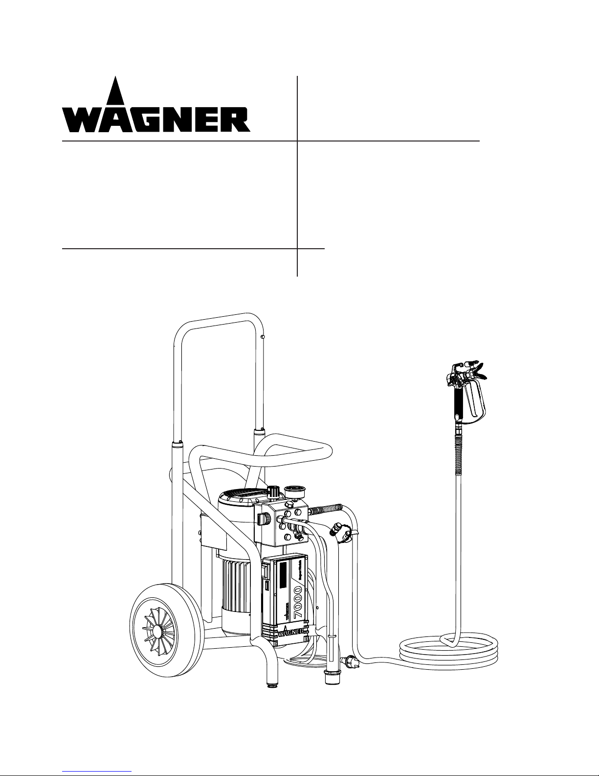
WAGNER Super Finish 7000 User manual

NEU
Airless – Hochdruck Spritzgerät
Airless high-pressure spraying unit
Appareil de pulvérisation à haute
pression Airless
Apparecchio di verniciatura a spruzzo
Airless ad alta pressione
Super Finish 7000
2306118
03 / 2011
Betriebsanleitung 2
Operating manual 33
Mode d‘emploi 63
Istruzioni per l‘uso 95
Originalbetriebsanleitung

33
Super Finish 7000 GB
WARNING!
Attention, danger of injury by injection!
Airless units develop extremely high spray pressures.
1Never bring ngers, hands or other body parts into contact with the spray jet!
Never point the spray gun at yourself, other persons or animals.
Never use the spray gun without spray jet safety guard.
Do not treat a spray injury as a harmless cut. In case of injury to the skin by coating material
or solvents, consult a doctor for quick and correct treatment. Inform the doctor about the
coating material or solvent used.
2The following points are to be observed in accordance with the operating manual
before every start-up:
1. Faulty units may not be used.
2. Secure a Wagner spray gun with the securing lever at the trigger guard.
3. Ensure earthing.
4. Check the permissible operating pressure of the high-pressure hose and spray gun.
5. Check all the connecting parts for leaks.
3Instructions for regular cleaning and maintenance of the unit are to be observed
strictly.
Observe the following rules before any work on the unit and at every working
break:
1. Relieve the pressure from the spray gun and high-pressure hose.
2. Secure a Wagner spray gun with the securing lever at the trigger guard
3. Switch the unit o.
Ensure safety!
Translation of the original operating instructions

34
Super Finish 7000
GB
contents
Contents
1 SAFETY REGULATIONS FOR AIRLESS SPRAYING 35
1.1 Flash point_________________________________ 35
1.2 Explosion protection_________________________ 35
1.3 Danger of explosion and re from sources of
ignition during spraying work _________________ 35
1.4 Danger of injury from the spray jet _____________ 35
1.5 Secure spray gun against unintended operation __ 35
1.6 Recoil of spray gun __________________________ 35
1.7 Breathing equipment as protection against
solvent vapors______________________________ 35
1.8 Noise protection ____________________________ 35
1.9 Prevention of occupational illnesses ____________ 36
1.10 Max. operating pressure______________________ 36
1.11 High-pressure hose (safety instructions) _________ 36
1.12 Electrostatic charging
(formation of sparks or ames) ________________ 36
1.13 Use of units on building sites and workshops_____ 36
1.14 Ventilation when spraying in rooms ____________ 36
1.15 Suction installations _________________________ 36
1.16 Earthing of the object________________________ 36
1.17 Cleaning the unit with solvents ________________ 36
1.18 Cleaning the unit ___________________________ 36
1.19 Work or repairs at the electrical equipment ______ 36
1.20 Work at electrical components_________________ 36
1.21 Working with a number of guns________________ 36
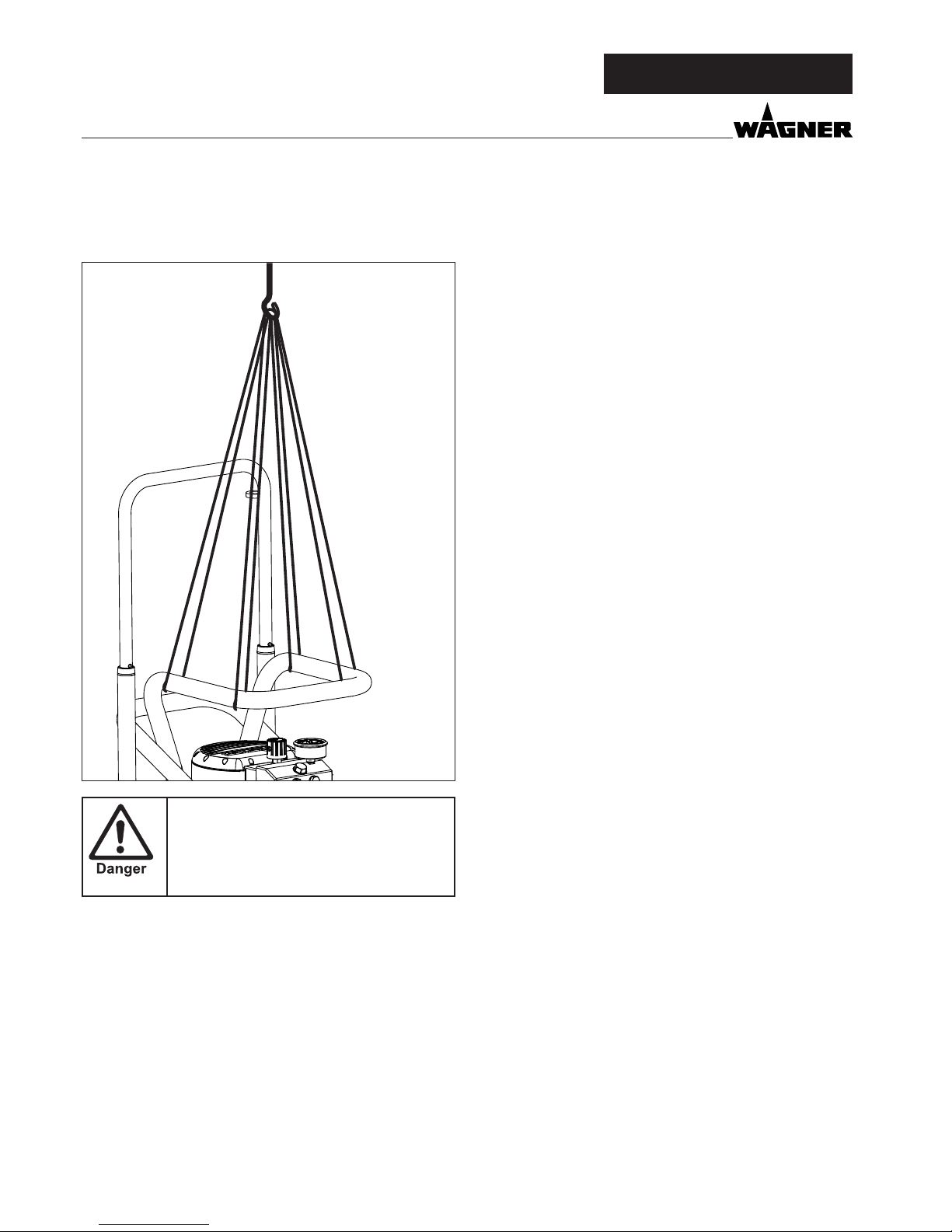
1.22 Transport using a crane ______________________ 36
1.23 Setup on an uneven surface___________________ 37
2 GENERAL VIEW OF APPLICATION ____________ 37
2.1 Application ________________________________ 37
2.2 Coating material ____________________________ 37
2.2.1 Coating materials with sharp-edged additional
materials __________________________________ 37
2.2.2 Filtering ___________________________________ 37
3. DESCRIPTION OF UNIT _____________________ 38
3.1 Airless process______________________________ 38
3.2 Functioning of the unit_______________________ 38
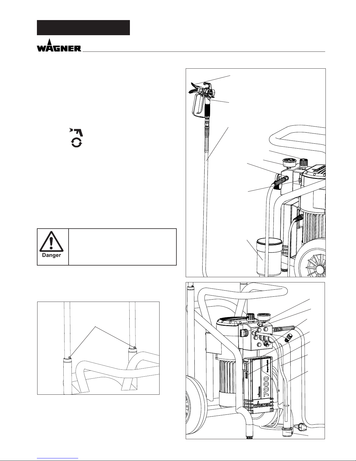
3.3 Explanatory diagram_________________________ 39
3.4 Transportation______________________________ 39
3.5 Transport using a crane ______________________ 40
3.6 Technical data Super Finish 7000_______________ 40
4 STARTUP _________________________________ 41
4.1 Unit with suction system _____________________ 41
4.2 High pressure hose and spray gun______________ 41
4.3 Connection to the mains network ______________ 42
4.4 Cleaning preserving agent when starting-up of
operation initially ___________________________ 42
4.5 Ventilate unit (hydraulic system) if the sound of
inlet valve is not audible______________________ 42
4.6 Taking the unit into operation with
coating material ____________________________ 43
5 SPRAYING TECHNOLOGY ___________________ 43
5.1 TempSpray (accessory) _______________________ 43
6 HANDLING THE HIGHPRESSURE HOSE _______ 43
6.1 High-pressure hose__________________________ 43
7 INTERRUPTION OF WORK ___________________ 43
8CLEANING THE UNIT _______________________ 44
8.1 Cleaning the unit from the outside _____________ 45
8.2 Suction lter _______________________________ 45
8.3 High-pressure lter __________________________ 45
8.4 Cleaning the Airless spray gun_________________ 46
9 SERVICING ________________________________ 46
9.1 General servicing ___________________________ 46
9.2 High-pressure hose__________________________ 46
10 REPAIRS AT THE UNIT ______________________ 46
10.1 Inlet valve Pusher ___________________________ 46
10.2 Inlet valve _________________________________ 47
10.3 Outlet valve ________________________________ 47
10.4 Pressure control valve________________________ 48
10.5 Relief valve ________________________________ 48
10.6 Replacing the diaphragm_____________________ 48
10.7 Replacing the power cable ___________________ 49
10.8 Typical wear parts ___________________________ 49
10.9 Connection diagram_________________________ 50
10.10 Remedy in case of faults ______________________ 52
11 SPARE PARTS AND ACCESSORIES ____________ 53
11.1 Super Finish 7000 accessories _________________ 53
11.2 Spare parts list Pump head ___________________ 56
11.3 Spare parts list Pump-Aggregate ______________ 57
11.4 Spare parts list high-pressure lter _____________ 59
11.5 Spare parts List Trolley _______________________ 59
11.6 Spare parts list suction system (rigid) ___________ 60
11.7 Spare parts list hopper _______________________ 60
Testing of the unit ________________________________ 61
Important information on product liability_____________ 61
Note on disposal__________________________________ 61
Guarantee declaration _____________________________ 61
CE - declaration__________________________________ 127
European service network _________________________ 128

35
Super Finish 7000
1.8 NOISE PROTECTION
Wear suitable ear protection when working.
GB
1 SAFETY REGULATIONS FOR
AIRLESS SPRAYING
The safety-specic requirements for Airless spraying are speci-
ed in:
a) The European Standard„Spray equipment for coating ma-
terials – safety regulations„ (EN 1953: 1998).
b) The regulations of the German employer‘s liability insur-
ance association („Berufsgenossenschaft“) „Using liquid
jets“ (BGV D15) and „Processing coating materials „ (BGV
D25).
c) Guidelines for construction and implementation require-
ments for liquid jets (spraying units) of the German indus-
trial employer‘s liability insurance association (ZH1/406).
The following safety regulations are to be observed in order
to ensure safe handling of the Airless high-pressure spraying
unit.
1.1 FLASH POINT
Only spray coating materials with a ash point
of 21 °C or higher.
The ash point is the lowest temperature at
which vapors develop from the coating ma-
terial. These vapors are sucient to form an
inammable mixture over the air above the
coating material.
1.2 EXPLOSION PROTECTION
Do not use the unit in work places which are
covered by the explosion protection regula-
tions.
The unit is not designed to be explosion pro-
tected.
1.3 DANGER OF EXPLOSION AND FIRE FROM
SOURCES OF IGNITION DURING SPRAYING
WORK
There must be no sources of ignition such as,
for example, open res, lit cigarettes, cigars or
tobacco pipes, sparks, glowing wires, hot sur-
faces, etc. in the vicinity.
1.4 DANGER OF INJURY FROM THE SPRAY JET
Attention, danger of injury by injection!
Never point the spray gun at yourself, other
persons or animals.
Never use the spray gun without spray jet
safety guard.
The spray jet must not come into contact
with any part of the body.
In working with Airless spray guns, the high
spray pressures arising can cause very dan-
gerous injuries. If contact is made with the
spray jet, coating material can be injected
into the skin. Do not treat a spray injury as a
harmless cut. In case of injury to the skin by
coating material or solvents, consult a doctor
for quick and correct treatment. Inform the
doctor about the coating material or solvent
used.
1.5 SECURE SPRAY GUN AGAINST UNINTENDED
OPERATION
Always secure the spray gun when mounting or dismounting
the tip and in case of interruption to work.
1.6 RECOIL OF SPRAY GUN
When using a high operating pressure, pull-
ing the trigger guard can eect a recoil force
up to 15 N.
If you are not prepared for this, your hand can
be thrust backwards or your balance lost. This
can lead to injury.
1.7 BREATHING EQUIPMENT AS PROTECTION
AGAINST SOLVENT VAPORS
Wear breathing equipment during spraying work.
A breathing mask is to be made available to the user (regu-
lations of the German employer‘s liability insurance associa-
tion („Berufsgenossenschaft“) „Rules for the use of breathing
masks“ (BGR 190), „Using liquid jets“ (BGV D15) and „Process-
ing coating materials„ (BGV D25).
safety regulatIons

36
Super Finish 7000
GB
safety regulatIons
1.9 PREVENTION OF OCCUPATIONAL ILLNESSES
Protective clothing, gloves and possibly skin protection cream
are necessary for the protection of the skin.
Observe the regulations of the manufacturer concerning coat-
ing materials, solvents and cleaning agents in preparation,
processing and cleaning units.
1.10 MAX. OPERATING PRESSURE
The permissible operating pressure for the spray gun, spray
gun accessories, unit accessories and high-pressure hose
must not fall short of the maximum operating pressure of 25
MPa (250 bar or 3625 psi).
1.11 HIGHPRESSURE HOSE SAFETY
INSTRUCTIONS
An electrostatic charging of spray guns and the high-pressure
hose is discharged through the high-pressure hose. For this
reason the electric resistance between the connections of the
high-pressure hose must be equal to or lower than 1 MΩ.
Only use WAGNER original-high-pressure
hoses in order to ensure functionality, safety
and durability.
1.12 ELECTROSTATIC CHARGING FORMATION OF
SPARKS OR FLAMES
Electrostatic charging of the unit may occur
during spraying due to the ow speed of
the coating material. These can cause sparks
and ames upon discharge. The unit must
therefore always be earthed via the electrical
system. The unit must be connected to an
appropriately-grounded safety outlet.
1.13 USE OF UNITS ON BUILDING SITES AND
WORKSHOPS
The unit may only be connected to the mains network via a
special feeding point with a residual-current device with INF
≤ 30 mA.
In the 400 volt version, a CEE 16A-6h socket with appropriate
fusing must be used for connection to the mains supply.
1.14 VENTILATION WHEN SPRAYING IN ROOMS
Adequate ventilation to ensure removal of the solvent vapors
has to be ensured.
1.15 SUCTION INSTALLATIONS
The are to be provided by the unit user in accordance with the
corresponding local regulations.
1.16 EARTHING OF THE OBJECT
The object to be coated must be earthed.
(Building walls are usually earthed naturally)
1.17 CLEANING THE UNIT WITH SOLVENTS
When cleaning the unit with solvents, the
solvent should never be sprayed or pumped
back into a container with a small opening
(bunghole). An explosive gas/air mixture can
arise. The container must be earthed.
1.18 CLEANING THE UNIT
Danger of short-circuits caused by water in-
gression!
Never spray down the unit with high-pres-
sure or high-pressure steam cleaners.
1.19 WORK OR REPAIRS AT THE ELECTRICAL
EQUIPMENT
These may only be carried out by a skilled electrician. No li-
ability is assumed for incorrect installation.
1.20 WORK AT ELECTRICAL COMPONENTS
Unplug the power plug from the outlet before carrying out
any repair work.
1.21 WORKING WITH A NUMBER OF GUNS
Changes to the device will aect all con-
nected guns.
Sudden pressure increases (activation/modi-
cation) can cause accidents.
Make sure that you know the status of all
connected spray guns/accessories and in-
form all other users if necessary.
1.22 TRANSPORT USING A CRANE
Do not suspend the device using the extendable shaft.

37
Super Finish 7000 GB
safety regulatIons
1.23 SETUP ON AN UNEVEN SURFACE
The front end must always point downwards in order to avoid
sliding away.
2 GENERAL VIEW OF APPLICATION
2.1 APPLICATION
Super Finish 7000 is an electric driven unit for the airless ato-
mization of dierent painting materials. Also it is able to feed
the internal feeded paint roller, which is available as accesso-
ry.
The performance of the Super Finish 7000 is designed to en-
able processing of dispersions for large objects both indoors
and outdoors (e.g. ceilings, facades, underground garages,
etc.).The use of corrosion protection and re protection is also
possible.
The unit is able for all common varnishing jobs like
doors, door frames, balustrades, furniture, woodencladding,
fences, radiators (heating) and steel parts.
The device is prepared for operation with several guns. How-
ever, this requires appropriate accessories, which are available
separately.
2.2 COATING MATERIAL
Dispersion and latex paints, two-component coating materi-
als, diluting lacquers and paints or those containing solvents.
No other materials should be used for spraying without
WAGNER‘s approval.
Pay attention to the Airless quality of the coa-
ting materials to be processed.
The unit is able to process coating materials with up to
15,000 mPas. If highly viscous coating materials cannot be ta-
ken in or the performance of the unit is to low, the paint must
be diluted in accordance with the manufacturer‘s instruc-
tions.
Multi-gun operation is not possible when
working with high viscosity coating materials.
Stir coating substance well before commencing work.
Attention: Make sure, when stirring up with
motor-driven agitators that no air bubbles
are stirred in. Air bubbles disturb when spra-
ying and can, in fact, lead to interruption of
operation.
2.2.2 FILTERING
Sucient ltering is required for fault-free operation. To this
purpose the unit is equipped with a suction lter (Item 1) and
an insertion lter in the spray gun (Item 2). Regular inspection
of these lters for damage or soiling is urgently recommen-
ded.
A high-pressure lter (Item 3) -available as accessory- is rising
up the ltering surface and will make the work more comfor-
table.
2.2.1 COATING MATERIALS WITH SHARPEDGED
ADDITIONAL MATERIALS
These particles have a strong wear and tear eect on valves
and tips, but also on the heating hose and spray gun. This im-
pairs the durability of these wearing parts considerably.
If possible do not use the unit on an inclined surface since the
unit tends to wander through the resulting vibrations.

38
Super Finish 7000
6 45 3
2 1
1
2
3
GB
general vIew of applIcatIon
3. DESCRIPTION OF UNIT
3.1 AIRLESS PROCESS
The main area of application are thick layers of highly viscous
coating material.
At the Super Finish 7000 unit a diaphragm pump takes in the
coating materials and transports it via a high-pressure hose
to the spray gun with the airless tip. Here the coating material
atomizes since it is pressed through the tip core at a maximum
pressure of 25 MPa (250 bar, 3625 psi). This high pressure has
the eect of micro ne atomisation of the coating material.
As no air is used in this process, it is described as an AIRLESS
process.
This method of spraying has the advantages of nest atomisa-
tion, cloudless operation (depending of a correct unit adjust-
ment) and a smooth, bubblefree surface. As well as these, the
advantages of the speed of work and convenience must be
mentioned.
3.2 FUNCTIONING OF THE UNIT
The following section contains a brief description of the tech-
nical construction for better understanding of the function:
Super Finish 7000 is an electrically driven high-pressure paint
spraying equipment.
The motor (Item 1) drives directly the hydraulic pump.
A piston (2) is moved up and down so that hydraulic oil is
moved under the diaphragm (3) which then moves.
In detail:
The downwards movement of the machine opens the disk in-
let valve (4) automatically and coating material is sucked in.
During the upwards movement of the diaphragm, the coating
material is displaced and the outlet valve (5) opens while the
inlet valve is closed.
The coating material ows under high pressure through the
high-pressure hose to the spray gun and is atomized when it
exists from the tip.
The pressure control valve (6) limits the set pressure in the
hydraulic oil circuit and thus also the pressure of the coating
material.
A pressure change when the same tip is used also leads to a
change in the amount of paint atomized.

39
Super Finish 7000
1
16
15
4
11
5
1
2
3
6
7
8
9
10
14
12
13
GB
descrIptIon of unIt
3.3 EXPLANATORY DIAGRAM
1 Tip guard with airless tip
2 Spray gun
3 High-pressure hose
4 Connection for high-pressure hose
5 Pressure gauge
6 Pressure control valve
7 Pressure relief valve
Symbols: Spraying
Circulation
8 ON / OFF switch
9 Indicating lamp (green indicates presence of line voltage)
10 Return hose
11 Suction system
12 Inlet valve button
13 Outlet valve
14 Oil measuring stick under the oil screw plug
15 Inlet lter
16 Storage container for exible suction system (Accessory.
Not included in the scope of supply.)
3.4 TRANSPORTATION
Device is very heavy (60 kg).
Only lift or carry the device in pairs.
Roll up the high-pressure hose and place over the carriage
frame.
Pull out the shaft.
Push or pull the device.
To retract the shaft, hold both buttons (1) pressed down.
Transportation in vehicle
Secure the unit in the vehicle by means of suitable fasteners.
The device can be placed on its side if necessary. In this case,
please ensure that no attachments can be damaged. Atten-
tion: Paint or solvent residues can escape from the connec-
tions!

40
Super Finish 7000
Do not suspend the device using the exten-
dable shaft.
GB
3.5 TRANSPORT USING A CRANE
For attaching points for the straps or rope (not wire cable) see
gure.
descrIptIon of unIt
3.6 TECHNICAL DATA SUPER FINISH 7000
Article no. basic unit 2305973 2306248
Voltage : 230 Volt ~,
50 Hz
400 Volt ~,
50 Hz
Fuses : 16 A time-lag 16 A
Unit connecting line : 6 m long,
3x1.5 mm²
6 m long,
5x1.5 mm²
Max. current consumption
hose heating : 13.5 A 5.8 A
Degree of protection : IP 44 IP 44
Acceptance capacity : 2.8 kW 3.1 kW
Max. operating pressure : 25 MPa
(250 bar)
25 MPa
(250 bar)
Max. volume ow : 7.2 l/min 7.2 l/min
Volume ow at 12 MPa
(120 bar) with water : 5.8 l/min 5.8 l/min
Max. temperature of the
coating material : 43 °C 43 °C
Max. viscosity : 15 000 mPas 15 000 mPas
Empty weight pump : 60 kg 60 kg
Hydraulic oil lling quantity: 1.5 litre 1.5 litre
Max. vibration at the spray
gun :
lower than
2.5 m/s²
lower than
2.5 m/s²
Max. sound pressure level: 82 dB (A)* 82 dB (A)*
*Place of measurement: 1 m distance from unit and 1.60 m
above oor, 12 Mpa (120 bar) operating pressure, reverberant
oor

41
Super Finish 7000
2 5
6
1
4
3
9
7
8
11
10
5
6
7
8
12
GB
Article no. basic unit 2305973 2306248
Voltage : 230 Volt ~,
50 Hz
400 Volt ~,
50 Hz
Fuses : 16 A time-lag 16 A
Unit connecting line : 6 m long,
3x1.5 mm²
6 m long,
5x1.5 mm²
Max. current consumption
hose heating : 13.5 A 5.8 A
Degree of protection : IP 44 IP 44
Acceptance capacity : 2.8 kW 3.1 kW
Max. operating pressure : 25 MPa
(250 bar)
25 MPa
(250 bar)
Max. volume ow : 7.2 l/min 7.2 l/min
Volume ow at 12 MPa
(120 bar) with water : 5.8 l/min 5.8 l/min
Max. temperature of the
coating material : 43 °C 43 °C
Max. viscosity : 15 000 mPas 15 000 mPas
Empty weight pump : 60 kg 60 kg
Hydraulic oil lling quantity: 1.5 litre 1.5 litre
Max. vibration at the spray
gun :
lower than
2.5 m/s²
lower than
2.5 m/s²
Max. sound pressure level: 82 dB (A)* 82 dB (A)*
*Place of measurement: 1 m distance from unit and 1.60 m
above oor, 12 Mpa (120 bar) operating pressure, reverberant
oor
4 STARTUP
4.1 UNIT WITH SUCTION SYSTEM
1. Unscrew the dust protective cap (Item 1).
2. Ensure that the sealing surfaces of the connections are
clean.
Ensure that the red inlet (2) is inserted in the coating ma-
terial inlet (5).
3. If using the suction system
Screw union nut (3) on suction system (4) to the coating
substance inlet (5) with the spanner provided (41mm) and
fasten nger-tight.
If using the upper container (accessories)
Screw container adapter (12) to coating substance inlet
(5) and fasten nger-tight. Place upper container (9) on
container adapter (12) and align. Place return hose (7) in
upper container.
4. Screw the union nut (6) at the return hose (7) to the con-
nection (8) (22mm).
4.2 HIGH PRESSURE HOSE AND SPRAY GUN
A special adapter is required for operation
with several guns (see accessories). Several
adapters can be connected together, so that
two additional guns can be used per adapter.
Multi-gun operation is not possible when
working with high viscosity coating materials.
1. Screw adapter for multiple-gun operation to hose con-
nection (if required).
2. Screw the high pressure hose (10) onto the hose connec-
tion or the adapter.
Unused connections on the adapter must be
sealed with the protective caps provided.
Only connect as many hoses as will be used.
All connected hoses are pressurised!
3. Screw the spray gun (11) onto the high pressure hose
4. Tighten all union nuts on high pressure hose so that no
coating material can escape.
5. Screw the tip holder with the selected tip onto the spray
gun, align tip and tighten union nut.
When unscrewing the high pressure hose,
hold rmly on the hose connection with a
22mm wrench.
startup

42
Super Finish 7000
GB
4.3 CONNECTION TOTHE MAINS NETWORK
Connection must always be carried out via
an appropriately grounded safety outlet with
residual-current-operated circuit-breaker.
Before connecting the unit to the mains supply, ensure that
the line voltage matches that specied on the unit’s rating
plate.
startup
4.4 CLEANING PRESERVING AGENT WHEN
STARTINGUP OF OPERATION INITIALLY
1. Immerse the suction system into a container lled with a
suitable cleaning agent (recommendation: water).
2. Switch on unit.
3. Turn the pressure regulating knob (1) to the right until
the stop is reached.
4. Open relief valve (2)
valve position (circulation)
5. Wait until cleaning agent is emitted from the return hose.
6. Turn the pressure regulating knob (1) back approx. one
rotation.
7. Close relief valve (2)
valve position (spraying), pressure is rising up inside
the high pressure hose (visible at pressure gauge)
8. Point the tip of the spray gun into an open collecting con-
tainer and pull the trigger guard at the spray gun.
9. The pressure is increased by turning the pressure regulat-
ing knob (1) to the right. Set approx. 10 MPa at the pres-
sure gauge.
10. Spray the cleaning agent out of the unit for approx.
1 - 2 min. (~5 litres) into the open collecting container.
4.6 TAKING THE UNIT INTO OPERATION WITH
COATING MATERIAL
1. Immerse the suction system into a container lled with
coating material.
2. Press inlet valve pusher (4) several times to release pos-
sibly clogged inlet valve
3. Open relief valve (2)
valve position (circulation)
4. Switch on unit.
5. Turn the pressure regulating knob (1) to the right until
the stop is reached.
When the noise of the valves changes, the unit is bled and
takes in coating material.
6. If coating material exits from the return hose, turn the
pressure regulating knob (1) back approx. 1 rotation.
7. Close relief valve (2)
valve position (spraying), pressure is rising up inside
the high pressure hose (visible at pressure gauge)
8. Pull of the spray gun and spray into an open collecting
container in order to remove the remaining cleaning
agent from the unit. When coating materials exits from
the tip, close the spray gun.
9. Pull of the spray gun and adjust the spraying pressure by
turning the pressure regulating knob (1).
10. The unit is ready to spray.
4.5 VENTILATE UNIT HYDRAULIC SYSTEM IF THE
SOUND OF INLET VALVE IS NOT AUDIBLE
1. Switch on the unit.
2. Turn pressure regulating knob (1) three revolutions to
the left.
3. Open relief valve (2)
valve position (circulation)
The hydraulic system is ventilated. Leave the unit on for
two or three minutes.
4. Then turn pressure regulating knob (1) to the right until
stop.
5. Press inlet valve pusher (4).
Sound of the inlet valve is audible.
6. If not, repeat points 2 and 4
1
2
3
4

43
Super Finish 7000
5.1 TEMPSPRAY ACCESSORY
The paint material is heated to the required temperature uni-
formly by an electric heating element, which is located inside
the hose (regulated from 20°C to 60°C).
Advantages:
• Constantpainttemperatureevenatlowoutsidetempera-
tures
• Considerablybetterworkingofhighviscositycoatingma-
terials
• Increaseapplicationeciency
• Savingsinsolventsduetoreductioninviscosity
TempSpray H 326 (ideal for
dispersions/materials with
high viscosity)
Order no. 2311661
Scope of delivery:
Basic unit 1/4“ incl. Hose reel,
heated hose DN10, 30m, hose
1/4“ DN4, 1m
GB
5 SPRAYING TECHNOLOGY
Move the spray gun evenly during the spraying process. If this
is not observed, an irregular spraying appearance will be the
result. Carry out the movement with the arm, not with the
wrist. A parallel distance of approx. 30 cm between the tip and
the surface to be coated should always be observed. The lat-
eral limitation of the spray fan should not to be too distinct.
The edge of spraying should be gradual to facilitate overlap-
ping of the next coat. The spray gun should always be held at
an angle of 90° to the surface to be coated. A spray fan aimed
obliquely at the surface to be coated leads to an unwanted
spray cloud.
Depending on the material, the use of a
smaller nozzle size or fewer guns can impro-
ve the spray pattern when using multiple-
gun operation.
To achieve perfect surfaces at varnishing works, special acces-
sories are available atWagner, e.g. FineFinish tips or an AirCoat
gun set. Your Wagner dealer will advise you.
6 HANDLING THE HIGHPRESSURE
HOSE
The high-pressure hose is to be handled with care. Avoid sharp
bending or kinking. The smallest bending radius amounts to
about 20 cm.
Do not drive over the high-pressure hose. Protect against
sharp objects and edges.
6.1 HIGHPRESSURE HOSE
The unit is equipped with a high-pressure hose specially suit-
ed for diaphragm pumps.
Only use WAGNER original-high-pressure
hoses with internal heating in order to ensure
functionality, safety and durability.
Longer hoses (30 m is optimal) reduce vibra-
tions.
7 INTERRUPTION OF WORK
1. Turn pressure regulating knob three revolutions to the
left.
2 Open relief valve (2)
valve position (circulation)
3. Switch o the unit
4. Pull the trigger guard on all spray guns in order to safe-
ly relieve the pressure of high-pressure hoses and spray
guns.
5. Secure the spray gun, refer to the operating manual of the
spray gun.
6. Remove tip from tip holder and store the tip in a small ves-
sel with suitable cleaning agent.
7. Leave the suction system immersed in the coating mate-
rial or immerse it in the corresponding cleaning agent.
The suction lter and unit should not dry out.
8. Cover the material container in order to prevent the paint
from drying.
When using quick-drying or two-component
coating substances, always ush the device
through with a suitable cleaning agent with-
in the processing time, as otherwise it will be
dicult to clean.
sprayIng technIque / handlIng the hIgh-pressure hose / InterruptIon of work
Danger of injury through leaking high-
pressure hose. Replace any damaged high-
pressure hose immediately.
Never repair defective high-pressure hoses
yourself!
When using the high-pressure hose while
working on scaolding, it is best to always
guide the hose along the outside of the scaf-
folding.

44
Super Finish 7000
GB
dIsplays at the unIt / cleanIng the unIt
8 CLEANING THE UNIT
A clean state is the best method of ensuring operation with-
out problems. After you have nished spraying, clean the unit.
Under no circumstances may coating material rests dry and
harden in the unit. The cleaning agent used for cleaning (only
with a ash point above 21 °C) must be suitable for the coat-
ing material used.
• Securethespraygun, refer to the operating manual of
the spray gun.
Remove and clean the tip and tip guard.
1. Open relief valve
valve position (circulation) and switch on unit
2. Remove suction system from the material container.
The return tube remains over the material container.
3. Immerse the suction system into a container lled with a
suitable cleaning agent
4. Turn the pressure control valve back in order to set a mini-
mal spraying pressure.
5. Close relief valve,
valve position (spraying)
6. Pull the trigger guard of the spray gun in order to pump the
remaining coating material from the suction hose, high-
pressure hose and the spray gun into an open container
(if appropriate, increase the pressure at the pressure con-
trol valve slowly in order to obtain a higher material ow).
When using multiple-gun operation the trigger guards
must be pulled in succession, in order to increase the
cleaning performance.
The container must be earthed in case of
coating materials which contain solvents.
Caution! Do not pump or spray in container
with small opening (bunghole)!
See safety regulations.
7. Open relief valve
valve position (circulation)
8. Pump suitable cleaning agent in the circuit for several
minutes.
Suction system with Quick Clean (points 9 to 17)
9. Screw the spray gun to the suction tube with both enclo-
sed 22 mm wrenches.
10. Pump a suitable cleaning agent in the circuit for about
1 minute.
11. Pull the trigger guard of the spray gun and lock it with a
clamp.
12. Close relief valve,
valve position (spraying)
13. Clean the suction tube about 3 minutes long.
14. Rinse in the circuit – Open relief valve
valve position (circulation).
15. Close the spry gun.
16. When cleaning with water repeat the procedure about 3
minutes long with clear water.
17. Remove spray gun from suction tube, close spray gun
connection at suction tube with closure nut.
The cleaning eect is increased by alterna-
tively opening and closing the spray gun.
18. Close relief valve,
valve position (spraying)
19. Pump the remaining cleaning agent into an open contain-
er until the pump is empty.
20. Switch o the unit
Warm water improves the cleaning eect in
the case of water-dilutable coating materials.
Unit with upper hopper
1. Open relief valve
valve position (circulation) and switch on unit
2. Turn the pressure control valve back in order to set a mini-
mal spraying pressure.
3. Close relief valve,
valve position (spraying)
4. Pull the trigger guard of the spray gun in order to pump
the remaining coating material from the hopper, high-
pressure hose and the spray gun into an open container (if
appropriate, increase the pressure at the pressure control
valve slowly in order to obtain a higher material ow).

45
Super Finish 7000
1
GB
The container must be earthed in case of
coating materials which contain solvents.
Caution! Do not pump or spray in container
with small opening (bunghole)!
See safty regulations.
5. Fill up hopper with suitable cleaning agent.
6. Open relief valve
valve position (circulation)
7. Pump suitable cleaning agent in the circuit for several mi-
nutes.
8. Close relief valve,
valve position (spraying)
9. Pump the remaining cleaning agent from the hopper,
high-pressure hose and the spray gun into an open con-
tainer
10. Open relief valve
valve position (circulation)
11. Switch o unit
8.1 CLEANING THE UNIT FROM THE OUTSIDE
First unplug the power plug from the outlet.
Danger of short-circuits caused by water
ingression! Never spray down the unit with
high-pressure or high-pressure steam clean-
ers.
The suction hose is only solvent-resistant to
a limited extent. Do not immerse in solvent,
only wipe.
Wipe down unit externally with a cloth which has been im-
mersed in a suitable cleaning agent.
8.2 SUCTION FILTER
Clean lters always ensure maximum volume,
constant spray pressure and problem-free
functioning of the unit.
Device with exible suction
system (accessory)
1. Unscrew the lter (Item 1)
from the suction tube (2).
2. Disassemble lter by rotat-
ing the base (3).
3. Clean or replace the lter.
Carry out cleaning with
a hard brush and a corre-
sponding cleaning agent.
8.3 HIGHPRESSURE FILTER
1. Open relief valve
valve position (circulation) - Switch the unit o.
2. Open the high-pressure lter and clean the lter insert. To
do so:
3. Unscrew the lter housing (1) by hand.
4. Remove the lter insert (2) and pull out the bearing spring
(3).
5. Clean all the parts with the corresponding cleaning agent.
If compressed air is available – blow through the lter in-
sert and bearing spring.
6. When mounting the lter ensure that the bearing ring (4)
in the lter insert is positioned correctly and check the O-
ring at the lter housing for damage.
7. Screw on the lter housing by hand until it stops (a higher
tightening force only impedes later dismantling).
1
3
2
Device with rigid suction system
1. Unscrew the lter (Item 1) from
the suction tube.
2. Clean or replace the lter.
Carry out cleaning with a hard
brush and a corresponding clea-
ning agent.
Unit with hopper
1. Release screws with a screwdriver.
2. Lift and remove lter disk with a screwdriver
3. Clean or replace the lter disk.
Carry out cleaning with a hard brush and a corresponding
cleaning agent.
cleanIng the unIt

46
Super Finish 7000
Insertion lter in Airless spray gun
1
3
2
GB
cleanIng the unIt / servIcIng
8.4 CLEANING THE AIRLESS SPRAY GUN
1. Rinse the Airless spray gun with a suitable cleaning agent
under lower operating pressure.
2. Clean the tip thoroughly with a suitable cleaning agent
so that no suitable coating material rests remain.
Do not use sharp objects to clean the nozzle.
3. Clean the outside of the Airless spray gun thoroughly.
Removal
1. Pull the protective bracket (1) forwards.
2. Screw the grip (2) out of the gun housing. Pull out the in-
sertion lter (3).
3. If the insertion lter is clogged or defective, replace it.
Installation
1. Slide the insertion lter (3) with the longer cone into the
gun housing.
2. Screw the grip (2) into the gun housing and tighten it.
3. Latch in the protective bracket (1).
9.1 GENERAL SERVICING
An annual expert check is highly recom-
mended to be sure to have a safe unit.
You can servicing of the unit carried out by
the Wagner Service. Favourable conditions
can be agreed with a service agreement and/
or maintenance packages.
Change hydraulic oil every 300 operating
hours or at least once a year.
Minimum check before every startup:
1. Check the high-pressure hose, spray gun with rotary joint,
power supply cable with plug for damage.
2. Check whether the pressure gauge can be read.
Check at periodical intervals:
1. Check inlet-, outlet-, relief valve according wear. Clean it
and replace worn out parts.
2. Check all lter inserts (spray gun, suction system) clean it
and replace if necessary.
9 SERVICING
9.2 HIGHPRESSURE HOSE
Inspect the high-pressure hose visually for any notches or
bulges, in particular at the transition in the ttings. It must be
possible to turn the union nuts freely. A conductivity of less
than 1 MΩ must exist across the entire length.
Have all the electric tests carried by the Wag-
ner Service.
10 REPAIRS AT THE UNIT
Switch the unit o.
Before all repair work: Unplug the power
plug from the outlet.
10.1 INLET VALVE PUSHER
1. Use a 17 mm spanner to screw out the inlet valve button.
2. Replace the wiper (1) and O-ring (2).

47
Super Finish 7000
2
5
31
6
4
12
1
56 4 3
27
GB
10.2 INLET VALVE
1. Place the enclosed 30 mm wrench on the trigger housing
(1).
2. Loosen the trigger housing (1) with light blows of a ham-
mer on the end of the wrench.
3. Screw out the trigger housing with the inlet valve (2) from
the paint section.
4. Pull of the clasp (3) using the enclosed screwdriver.
5. Place the enclosed 30 mm wrench on the inlet valve (2).
Turn out the inlet valve carefully.
6. Clean the valve seat (4) with a cleaning agent and brush
(ensure that no brush hairs are left behind).
7. Clean the seals (5, 6) and check for damage. Replace, if
necessary.
8. Check all the valve parts for damage. In case of visible
wear replace the inlet valve.
repaIrs at the unIt
Installation
1. Insert the inlet valve (2) into the trigger housing (1) and
secure with the clasp (3). Ensure that the (black) seal (5) is
mounted in the trigger housing.
2. Screw the unit from the trigger housing and the inlet valve
into the paint section. The white seal (6) must be tted in
the colour stage.
3. Tighten the trigger housing with the 30 mm wrench and
tighten with three light blows of the hammer on the end
of the wrench. (Corresponds to approx. 90 Nm tightening
torque).
10.3 OUTLET VALVE
1. Use a 22 mm wrench to screw the outlet valve from the
paint section.
2. Carefully pull of the clasp (1) using the enclosed screw-
driver. The compression spring (2) presses ball (4) and
valve seat (5) out.
3. Clean or replace the components.
4. Check the O-ring (7) for damage.
5. Check the installation position when mounting the spring
support ring (3) (clipped onto spring (2)), outlet valve seat
(5) and seal (6), refer to gure.

48
Super Finish 7000
1
1
2
6
1
4
2
5
3
GB
repaIrs at the unIt
10.4 PRESSURE CONTROL VALVE
Only have the pressure control valve (1) re-
placed by the customer service.
The max. operating pressure has to be reset
by the customer service.
10.5 RELIEF VALVE
Replace a fault relief valve (1) as a single unit.
Only the O-ring (2) may be replaced as a single part
10.6 REPLACING THE DIAPHRAGM
Switch the unit o.
Before all repair work: Unplug the power
plug from the outlet.
1. Screw the trigger housing with inlet valve out of the paint
section as described in Section 10.2 Inlet valve, Items 1 to
3. (disassembling of hexagon nuts will become easier)
2. Turn back the pressure control valve, rotary knob com-
pletely (anti-clockwise).
(Note: If the unit is still warm, open the oil screw plug (6)
briey in order to compensate the pressure and close it
again.)
3. Use a 19 mm wrench to screw the hexagonal bolt (Item 1)
out of the ange ring (2).
4. Remove the paint section (3).
5. Remove the insert (4) and the diaphragm (5).
6. The diaphragm can only be used once. Always replace the
diaphragm.

49
Super Finish 7000
23
Representation of
230 V version
14
2
3
Representation of
400 V version
GB
repaIrs at the unIt
Before mounting the new diaphragm, clean the insert as well
as the grooved surface at the pressure insert (2) and the paint
section (3) and wipe o any oil.
Mounting is carried out in the reverse order.
1. First tighten all the hexagonal bolts (1) crosswise with
30Nm, then crosswise with 70Nm.
2. Before starting up leave the pressure control valve in the
open position for about 2 minutes while the motor is run-
ning (bleeds the unit). Only then close it until the noise of
the inlet valve can be heard.
10.7 REPLACING THE POWER CABLE
10.8 TYPICAL WEAR PARTS
Despite the use of high-quality materials the highly abrasive
eect of the paints means that wear can occur at the follow-
ing parts:
Inlet valve (spare part Order No.: 0254 524)
For replacing refer to Section 10.2
(failure becomes noticeable through performance loss and/or
poor or no suction)
Outlet valve (spare part Order No.: 0341702)
For replacing refer to Section 10.3
(failure becomes noticeable through performance loss and/
or poor suction) The outlet valve is usually considerably more
durable than the inlet valve. Thorough cleaning may already
help here.
Relief valve (spare part Order No.: 0169248)
For replacing refer to Section 10.5
(failure is noticeable through performance loss. Furthermore
material arrives constantly at the return hose although the
multifunction switch is set to spraying.
This part is relatively seldom a wear part.
Work or repairs at the electrical equipment
may only be carried out by a skilled electri-
cian. No liability is assumed for incorrect in-
stallation.
Switch the unit o.
Before all repair work: Unplug the power
plug from the outlet.
1. Dismount the cover (1) by loosening the 6 recessed-head
screws (4).
2. Loosen the cable threaded joint (2).
3. Loosen the wires in the mains terminal (3) .
4. Replace the unit connecting line.
(only an approved power cable with the designation H07-
RNF with a splash-proof plug may be used).
5. Connect the green/yellow wire to the contact with the PE
sign.
6. Connect the cover again and mount it carefully (do not
squeeze any cables!)

50
Super Finish 7000
GB
repaIrs at the unIt
10.9 CONNECTION DIAGRAM 230 VOLT VERSION

51
Super Finish 7000 GB
CONNECTION DIAGRAM 400 VOLT VERSION
repaIrs at the unIt
Other manuals for Super Finish 7000
1
Table of contents
Other WAGNER Pressure Washer manuals