manuals.online logo
Brands
  1. Home
  2. •
  3. Brands
  4. •
  5. Walchem
  6. •
  7. Controllers
  8. •
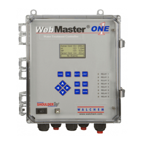
  9. Walchem W100 User manual

Walchem W100 User manual

CAUTION: There are live circuits inside the controller even when the power switch is in the
OFF position! Servicing and troubleshooting the controller must be performed by
Qualified
Service Personnel.
1
W100/W600/W900 Controller
pH Electrode Troubleshooting Guide
Table of Contents
Section 1
Electrode Reading Responds Slowly
Section 2
Electrode Reading is Stuck on one Value
Section 3
Electrode Reads Low or High Versus a Calibrated Handheld Meter; Cannot Calibrate
Section 4
Electrode Fault
Section 5
pH Reading is Unstable
Note: pH electrodes are like batteries and their output voltage will change with time, even if they are not being
used. The useful life of a pH electrode is limited, and that time varies with the conditions it’s exposed to in the
application. Electrode life may be as short as one week in some aggressive applications (extreme temperature, pH
and/or pressure, dirty water, harsh chemicals) or more than a year in other applications with potable quality water at
room temperature.
CAUTION: There are live circuits inside the controller even when the power switch is in the
OFF position! Servicing and troubleshooting the controller must be performed by
Qualified
Service Personnel.
2
This Troubleshooting Guide covers pH electrode troubleshooting whether the electrode is connected to the WEL-PH Housing
or to the WEL Transmitter Housing.
The WEL-PH Housing is a direct sensor input, which means it wires into the controller sensor input terminals.
oThe WEL-PH Housing works with the W100, W600 and W900 controllers.
The WEL Transmitter Housing is an analog input, which means it wires into the controller analog input terminals.
oThe WEL Transmitter Housing only works with the W600 and W900 controllers, not with the W100 controller.
You can determine which configuration you have based on the following.
The WEL-PH Housing and the WEL Transmitter Housing will look physically identical. To tell them apart, please look at the
end of the sensor cable (that will connect to the controller).
The WEL-PH Housing will have either 4 (No Automatic Temperature Compensation) wires, or 6 wires (Automatic Temperature
Compensation), plus a shield wire.
The WEL Transmitter Housing will have 2 wires plus a shield wire. The Auto Temp Comp is built into the housing.
4 wire WEL-PH Housing plus shield, no Auto
Temp Comp
6 wire WEL-PH Housing plus shield, has
Auto Temp Comp
CAUTION: There are live circuits inside the controller even when the power switch is in the
OFF position! Servicing and troubleshooting the controller must be performed by
Qualified
Service Personnel.
3
Section 1: Electrode Reading Responds Slowly
Step 1:
pH electrodes require periodic cleaning and calibration.
The method of cleaning the electrode will depend upon the coating, as well as the
materials of construction of the electrode. Do not use a solvent that will attack the
electrode.
Oily coatings should be removed with a mild detergent or isopropyl alcohol.
Hard scales such as calcium carbonate can usually be removed with a dilute
hydrochloric acid solution.
Soft coatings can be removed using a soft cloth or soft toothbrush.
A two-point calibration should always be performed after cleaning the electrode.
Step 2:
If cleaning does not speed up the electrode's response
Replace the electrode.
CAUTION: There are live circuits inside the controller even when the power switch is in the
OFF position! Servicing and troubleshooting the controller must be performed by
Qualified
Service Personnel.
4
Section 2 (A): WEL-PH Housing + Electrode Reading is Stuck on one Value
Step 1:
The following are normal (expected) readings when the controller electrode input is programmed as pH,
and the following configurations are in place:
With nothing connected to the electrode input terminals in the controller, the reading should
be about 0 mV (7 pH).
With just the WEL-PH housing wired into the electrode input terminals in the controller (but no
electrode installed), the reading should float (vary low to high to low to high, etc.).
With the WEL-PH housing wired into the electrode input terminals in the controller, and the
electrode threaded into the housing, the reading should be the pH value of the solution, as
verified by a secondary means, such as a handheld pH meter.
Step 2:
If a controller’s electrode input is programmed as pH, and the controller has a WEL-PH housing wired
into the correct electrode input terminals (with the electrode threaded into the housing), and the pH
reading is stuck on some incorrect pH value, please check the following:
There could be an electrical short between controller input terminals IN+ and IN-
•Either the electrode wires, or electrode cable wires, are contacting each other when they
normally should not be.
The glass on the end of the electrode could be broken or compromised.
There is an open circuit between controller input terminals IN+ and IN-
•This could mean the electrode/electrode cable has broken wires.
CAUTION: There are live circuits inside the controller even when the power switch is in the
OFF position! Servicing and troubleshooting the controller must be performed by
Qualified
Service Personnel.
5
Section 2 (B): WEL Transmitter Housing + Electrode Reading is Stuck on
one Value or Reading Erratically
Note: This section is applicable to W600 and W900 controllers (not applicable to W100
controllers).
The WEL Transmitter housings are:
For use with ORP electrodes (cartridges), with a 4-20 mA range scaled to -500 to 1000 mV.
The other has automatic temperature compensation (measured by an RTD) for use with pH
electrodes (cartridges), with a 4-20 mA range scaled to 0 to 14 pH standard units.
Note: The WEL Transmitter Housing + pH Electrode will output a 4-20mA signal
only, there will not be a separate temperature reading sent to the controller.
Automatic temperature compensation takes place inside the WEL Transmitter
Housing.
The following are normal (expected) readings when the controller electrode input is programmed as pH,
and the following configurations are in place:
With nothing connected to the analog input terminals in the controller, the reading should be
about 0 mV (7 pH).
With just the WEL Transmitter housing wired into the analog input terminals in the controller (but
no electrode installed), the reading should float (vary low to high to low to high, etc.).
With the WEL Transmitter housing wired into the analog input terminals in the controller, and the
electrode threaded into the housing, if the RTD (automatic temperature compensation) fails in
the open position (wires somehow disconnected inside the housing) the reading should be stuck
at 0mV (7pH).
With the WEL Transmitter housing wired into the analog input terminals in the controller, and the
electrode threaded into the housing, if the RTD (automatic temperature compensation) fails in
the closed position (wires somehow shorted inside the housing) the reading should float (vary
low to high to low to high, etc.).
With the WEL Transmitter housing wired into the analog input terminals in the controller, and the
electrode threaded into the housing, if the glass on the end of the electrode breaks, the reading
should be a constant 12.0 mA (7pH).
CAUTION: There are live circuits inside the controller even when the power switch is in the
OFF position! Servicing and troubleshooting the controller must be performed by
Qualified
Service Personnel.
6
Section 3 (A): WEL-PH Housing + Electrode Reads Low or High Versus a
Calibrated Handheld Meter; Cannot Calibrate the Electrode
Step 1:
pH value versus mV reading
This menu displays the mV measured by the electrode.
For every pH unit above 7, the mV value should
change by about –59 mV. For every pH unit below 7,
the mV value should change by about +59 mV.
Step 2:
pH and temperature relationship
•pH electrodes can be ordered with Automatic Temperature Compensation (ATC), or not.
•If the pH electrode comes with ATC:
oLook for the temperature leads from the electrode housing
oUsually they are green and white/green leads.
If the pH electrode has ATC, the next step is to verify the controller has the correct temperature
element programmed into the Temperature Input menu, and it is reading the correct
temperature. Typically, temperature element = RTD1000 Ω for Walchem pH electrodes.
Temperature element:
•Some electrodes do not have ATC. If you are not using ATC, in the Inputs
menu/Temperature/Settings, scroll to Element, and select No Element. And whatever
the water sample temperature is, set that as the Default Temperature in the pH Input
menu.
•If the electrode you are using has ATC, and if the temperature reading is the problem,
there is a resistance reading that correlates to the temperature reading. From the
controller touchpad, you can check the resistance reading in the Inputs
menu/Temperature section. The resistance reading should be 1000 ohm + 3.85 ohms
per degree C above 25C. Below is how the math works. If the resistance reading in the
controller matches (or is very close to) the math below, then the electrode temperature
element and the controller are not the issue.
The 1000 Ω RTD has a resistance of 1000 ohms at 0C (32F). And the resistance goes up by
3.85 ohms per degree C. Here are some examples:
•At 25C it should read 1000 + (25 * 3.85) = 1000 + 96.25 = 1096.25 ohms.
•At 50C it should read 1000 + (50 * 3.85) = 1000 + 192.5 = 1192.5 ohms.
•At 100C it should read 1000 + (100 * 3.85) = 1000 + 385 = 1385 ohms.
•At 150C it should read 1000 + (150 * 3.85) = 1000 + 578 = 1578 ohms.
•At 180C it should read 1000 + (180 * 3.85) = 1000 + 693 = 1693 ohms.
CAUTION: There are live circuits inside the controller even when the power switch is in the
OFF position! Servicing and troubleshooting the controller must be performed by
Qualified
Service Personnel.
7
Section 3 (A): WEL-PH Housing + Electrode Reads Low or High Versus a
Calibrated Handheld Meter: Cannot Calibrate the Electrode (continued)
If the resistance reading is incorrect, disconnect the WHITE/GREEN wires from the terminal
strip inside the controller and using a multimeter, set to resistance (ohms), measure the
resistance across the WHITE/GREEN and GREEN/WHITE wires coming directly from the
electrode. Reading should be 1000 ohm + 3.85 ohms per degree C above 0°C. If reading is
incorrect, the temperature element in the electrode is bad. If the resistance reading is good, yet
it still displays the temperature incorrectly, the problem is with the controller front panel.
If the problem is the controller front panel, please contact your supplier of Walchem equipment.
Step 3:
Calibration fails
•In the controller’s pH Electrode Input menu, look at the pH Raw Value and the Gain
Value.
•What is the calibration range that you are allowed to go to?
oThe controller shows us a current pH reading and a raw pH reading.
oThis raw value is in mV units.
oThe range (referred to as gain) that the controller will allow you to calibrate to
uses the raw pH as a reference point.
oGain is a value that the controller calculates, and it tells us how far you are
calibrating from the raw pH value.
oFor pH electrodes, the calibration will fail if the adjustment to the gain is outside
of the 0.2 to 1.2 range, or if the calculated offset is outside of -140 to +140mV.
• What is Offset?
• Offset = this is the mV value that the pH electrode is measuring at pH=7
• Normal offset at pH=7 should be approximately +/-10mV
• The controller software allows this range to be -140 to +140mV
To re-establish a starting point, the controller allows you to reset the calibration values as
follows:
•Go to the pH Electrode Inputs menu. Press the Settings key, then the Down arrow until
you see Reset Calibration Values. Press on the Reset Calibration field, and then press
the Check mark to accept.
•You should now perform a pH electrode calibration in accordance with the controller
manual.
CAUTION: There are live circuits inside the controller even when the power switch is in the
OFF position! Servicing and troubleshooting the controller must be performed by
Qualified
Service Personnel.
8
Section 3 (B): WEL-Transmitter Housing + Electrode Reads Low or High Versus
a Calibrated Handheld Meter; Cannot Calibrate the Electrode
pH value versus mA reading
The pH analog input menu displays the mA measured by the electrode, with a 4-20
mA range scaled to 0 to 14 pH standard units. As a reference, please see the table
below. However, these reference points may change subsequent to calibration.
If the pH (mA) reading is not correct, using a multimeter, please check the mA signal coming
from the sensor and into the controller as follows:
•Place the WEL Transmitter Housing plus Electrode in the system tee/water, or place it in
a buffer solution.
•Power down the controller. Disconnect either the red or the black sensor lead (not the
shield wire) and connect a multimeter in series as shown below to measure current (mA)
•Power up the controller. The multimeter will display the mA going to the controller from
the sensor.
oIf the mA value is stuck on one value, no matter if the sensor is in the system
tee/water or in different buffer solutions, then please refer to Section 2B in this
guide.
oIf the mA value differs from the from the chart above, please perform a One point
or Two Point calibration in accordance with the controller manual.
mA
pH
4
0
12
7
20
14
CAUTION: There are live circuits inside the controller even when the power switch is in the
OFF position! Servicing and troubleshooting the controller must be performed by
Qualified
Service Personnel.
9
Section 4: WEL-PH Housing + Electrode (Sensor) Fault
Step 1:
Electrode Fault
•This error indicates that the signal from the electrode is no longer valid at all. This error
condition with stop control of any output using the electrode.
Possible Cause
Corrective Action
Electrode wires shorted
Disconnect short
Faulty electrode
Replace electrode
Faulty controller
Replace or repair controller
Controller, Power, Display, or Electrode Board Error
•This alarm occurs if the board listed is not recognized.
Possible Cause
Corrective Action
Poor ribbon cable connection
Remove and reseat ribbon cable, cycle power
Poor option card connection (not applicable to
W100)
Remove and reseat the board, cycle power
Faulty board
Replace or repair controller
CAUTION: There are live circuits inside the controller even when the power switch is in the
OFF position! Servicing and troubleshooting the controller must be performed by
Qualified
Service Personnel.
10
Section 5: WEL-PH Housing + Electrode OR WEL Transmitter Housing +
Electrode Reading is Unstable
Step 1:
The pH reading is unstable when the pH electrode is
placed in the system water.
Remove the pH electrode from the system water and
place it in a beaker of water. Does the reading
stabilize? If yes, then proceed to Step 2. If no,
proceed to Step 3.
Step 2:
The electrode is still in the beaker of water, and the reading is stable.
Obtain a length of wire (the ends of the wire must be stripped) long enough to place
one end in the water in the beaker, and the other end in the system water.
With this length of wire connecting the beaker water to the system water, does the
reading stay stable?
If the reading does not stay stable, this can indicate a ground loop. A ground loop
could cause readings to be stuck at a high or low value. Or there is some electrical
interference in the system water, possibly from a mixer, recirculation pump, etc.
Removing power from each device and checking to see if the reading stabilizes can
help determine the source of the electrical interference.
Step 3:
The electrode is still in the beaker, and the reading is still unstable.
Power down the controller, disconnect the pH electrode shield wire from the Earth
ground stud inside the controller.
Does the reading stabilize?
If the reading stabilizes, then there is possibly some electrical noise coming in
through the controller VAC mains.
If the reading does not stay stable, then connect the controller to an alternate
supply voltage circuit. This may necessitate temporarily running an extension cord
for this test. If the reading still does not stay stable, please contact your supplier of
Walchem equipment for further instructions.

Other manuals for W100

1

This manual suits for next models

2

Other Walchem Controllers manuals

Walchem W100 Owner's manual

Walchem

Walchem W100 Owner's manual

Walchem WTCW100 Series User manual

Walchem

Walchem WTCW100 Series User manual

Walchem WBL400 Series User manual

Walchem

Walchem WBL400 Series User manual

Walchem WebMaster User manual

Walchem

Walchem WebMaster User manual

Walchem W900 Series User manual

Walchem

Walchem W900 Series User manual

Walchem WDT400 Series User manual

Walchem

Walchem WDT400 Series User manual

Walchem W600 Series User manual

Walchem

Walchem W600 Series User manual

Walchem WDP Series User manual

Walchem

Walchem WDP Series User manual

Walchem WebMaster User manual

Walchem

Walchem WebMaster User manual

Walchem W600 Series User manual

Walchem

Walchem W600 Series User manual

Walchem W900 Series Operating instructions

Walchem

Walchem W900 Series Operating instructions

Walchem WDIS Series User manual

Walchem

Walchem WDIS Series User manual

Walchem WCU Series User manual

Walchem

Walchem WCU Series User manual

Walchem WebMaster User manual

Walchem

Walchem WebMaster User manual

Walchem WCT400 Series User manual

Walchem

Walchem WCT400 Series User manual

Walchem WDP420 User manual

Walchem

Walchem WDP420 User manual

Walchem WDB400 Series User manual

Walchem

Walchem WDB400 Series User manual

Walchem W600 Series User manual

Walchem

Walchem W600 Series User manual

Popular Controllers manuals by other brands

SunFounder ESP32 manual

SunFounder

SunFounder ESP32 manual

Phoenix Contact MCR-FL-D-U-I-2SP-24 manual

Phoenix Contact

Phoenix Contact MCR-FL-D-U-I-2SP-24 manual

Explorer FX15 Technical bulletin

Explorer

Explorer FX15 Technical bulletin

Johnson Controls VMA1617 installation guide

Johnson Controls

Johnson Controls VMA1617 installation guide

Audioaccess PX-700 manual

Audioaccess

Audioaccess PX-700 manual

Epson BO-IC400 user guide

Epson

Epson BO-IC400 user guide

Loctite CL10 Operation manual

Loctite

Loctite CL10 Operation manual

EuropeGas OSCAR-N PLUS SAS user manual

EuropeGas

EuropeGas OSCAR-N PLUS SAS user manual

Carel ir33 Universale Replacement instructions

Carel

Carel ir33 Universale Replacement instructions

IEI Technology VWBOX-E133 user manual

IEI Technology

IEI Technology VWBOX-E133 user manual

Moen ARC-4200 installation guide

Moen

Moen ARC-4200 installation guide

Maxcess Fife GMA-BL Quick start manual

Maxcess

Maxcess Fife GMA-BL Quick start manual

WeatherTRAK ET Pro 2 Series Manual/quick reference guide

WeatherTRAK

WeatherTRAK ET Pro 2 Series Manual/quick reference guide

LDA Audio Tech VCC-64 user manual

LDA Audio Tech

LDA Audio Tech VCC-64 user manual

IPAS PowerBlock o16 Multi Operating and mounting instructions

IPAS

IPAS PowerBlock o16 Multi Operating and mounting instructions

3M MicroTouch EX Series reference guide

3M

3M MicroTouch EX Series reference guide

Huber Pilot ONE Operation manual

Huber

Huber Pilot ONE Operation manual

Galaxy Control Systems 635 Series Worksheet

Galaxy Control Systems

Galaxy Control Systems 635 Series Worksheet

manuals.online logo
manuals.online logoBrands
  • About & Mission
  • Contact us
  • Privacy Policy
  • Terms and Conditions

Copyright 2025 Manuals.Online. All Rights Reserved.