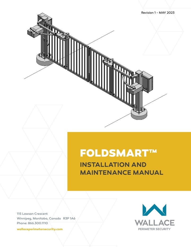
Wallace Perimeter Security SPEEDGATE Manual

Revision 1 - MAY 2023
115 Lowson Crescent
Winnipeg, Manitoba, Canada R3P 1A6
Phone: 866.300.1110
wallaceperimetersecurity.com
SPEEDGATE
INSTALLATION AND
MAINTENANCE MANUAL
Gen II Models – Pdtt Series & Pdxt-C Series
[INTRODUCED 2021]

2wallaceperimetersecurity.comPhone: 866.300.1110
• This installaon and maintenance manual edion replaces all earlier versions.
• The specicaons contained in this document may be changed without prior noce.
• Keep this manual in the operang area.
• Make sure that the maintenance is carried out in accordance with the direcons. Use checklists
for recording repairs and maintenance to the SpeedGate, and maintain permanent logs of all gate
inspecons, maintenance, servicing and repair acvies. See “Inspecon, Servicing and Maintenance”
on page 129 for general inspecon and maintenance guidelines.
• Follow the safety instrucons contained in the manual.
• Wallace Perimeter Security reserves the right to modify the SpeedGate manual without prior
nocaon.
• This manual has been wrien with the utmost care and aenon. However, the possibility of errors
cannot be excluded. Wallace Perimeter Security is not liable for damage arising as a result of errors
which occur in the manual. Please inform us immediately of any errors or omissions you may idenfy.
Copyright Noce
©Copyright 2023 all rights reserved. No part of this manual may be reproduced by any means (photocopier,
electronic, or mechanical), without the express wrien permission of Wallace Perimeter Security.

SPEEDGATE Installation and Maintenance Manual Revision 1 - MAY 2023 3
TABLE OF CONTENTS
SAFETY NOTICES ��������������������������������������������������������������������������������������������6
Informaon Noces���������������������������������������������������������������������������������������6
READ THIS FIRST!�������������������������������������������������������������������������������������������7
Important Informaon�����������������������������������������������������������������������������������7
Foreword�������������������������������������������������������������������������������������������������������7
Installaon and Commissioning Checklist ������������������������������������������������������8
Installaon and Commissioning Checklist: Seng Gate Limits��������������������� 10
Installaon and Commissioning Checklist: Seng Gate Limits��������������������� 11
Safety Requirements ������������������������������������������������������������ 16
Safety Informaon for SpeedGates ��������������������������������������������������������������16
Safety Consideraons for Designers, Installers and Users�����������������������������17
Safety Standards - Installer’s Responsibility �������������������������������������������������18
Important Safeguards and Instrucons to Communicate to Owners/Users ��19
Applicaon: Idenfying Gate System Category and Usage Class ������������������21
Introducing SpeedGate��������������������������������������������������������� 23
Product Descripon������������������������������������������������������������������������������������� 23
Safety Devices ���������������������������������������������������������������������� 26
Open & Close Cycle�������������������������������������������������������������������������������������� 26
Inherent Entrapment Sensor������������������������������������������������������������������������ 26
External Entrapment Protecon Sensors������������������������������������������������������29
Choosing External Entrapment Protecon���������������������������������������������������� 30
UL 325 Compliant Sensors ��������������������������������������������������������������������������� 31
External Entrapment Sensor Types��������������������������������������������������������������� 34
Installer and User Safety Consideraons������������������������������� 37
Safety and Health Hazards ��������������������������������������������������������������������������� 37
Entrapment Protecon and Pinch Points������������������������������������������������������37
Warning Signs���������������������������������������������������������������������������������������������� 40
Addional Safety Features���������������������������������������������������������������������������41
Recommended Safety Precauons for the Immediate Vicinity ��������������������� 42
Safety Instrucons for Maintenance ������������������������������������������������������������ 43
TABLE OF CONTENTS

4wallaceperimetersecurity.comPhone: 866.300.1110
SpeedGate Delivery and Unloading �������������������������������������� 44
SpeedGate Installaon ��������������������������������������������������������� 45
Foong and Foundaon Installaon ������������������������������������������������������������45
Gate Installaon ������������������������������������������������������������������������������������������49
Operator Cabinet Installaon Consideraons�����������������������������������������������54
Installaon Adjustments������������������������������������������������������� 55
Drawbar Adjustment Procedure ������������������������������������������������������������������ 55
Wiring Installaon���������������������������������������������������������������� 57
PDXT, PDXT-C and PDTT Electrical Point-to-Point Diagrams - 1����������������������59
PDXT, PDXT-C and PDTT Electrical Point-to-Point Diagrams - 2����������������������61
PDXT, PDXT-C and PDTT Electrical Point-to-Point Diagrams - 3����������������������63
Primary & Secondary Operator for a Standard Post Drive Gate SpeedGate���65
Wire Sizes, Types and Locaons �������������������������������������������������������������������67
Photo Eye Installaon����������������������������������������������������������������������������������70
Photo Eye Alignment ����������������������������������������������������������������������������������� 73
GATE OPTIONS��������������������������������������������������������������������������������������������� 75
Installaon Instrucons for Oponal Gate Edges ����������������������������������������� 75
UL 325 Monitoring Requirement for External Entrapment Protecon Devices
�������������������������������������������������������������������������������������������������������������������� 78
Installaon Instrucons for Oponal Vehicle Detectors�������������������������������� 80
Oponal Gate Status Proximity Sensors and Mounng Plates ����������������������85
Oponal Strobe / Trac Lights ��������������������������������������������������������������������85
ELECTRICAL CIRCUITS�����������������������������������������������������������������������������������86
Post Terminaon Box�����������������������������������������������������������������������������������86
Electrical Circuit – OPERATOR ���������������������������������������������������������������������� 92
PDXT-C or PDTT-Max Sample Wiring Diagrams������������������������������������������� 101
Manual Operaon Using the Brake Disconnect Cable ��������� 112
Gate Sengs: Obstacle Detecon��������������������������������������� 114
Seng the Reduced Speed Sensor/Torque Change Sensor������������������������� 114
Seng the Obstacle Detecon������������������������������������������������������������������� 114
TABLE OF CONTENTS

SPEEDGATE Installation and Maintenance Manual Revision 1 - MAY 2023 5
Troubleshoong ����������������������������������������������������������������� 115
Details on How to Troubleshoot the SpeedGate����������������������������������������� 115
Operator Fault Codes��������������������������������������������������������������������������������� 115
Details on How to Operate the Gate ���������������������������������������������������������� 128
Controlled Constant Contact Operaon ����������������������������������������������������� 128
Automac Controlled Momentary Operaon��������������������������������������������� 128
Inspecon, Servicing and Maintenance������������������������������� 129
How to Maintain a SpeedGate ������������������������������������������������������������������� 129
Maintenance, Repair and Servicing Assistance������������������������������������������� 129
Periodic Maintenance to the Enre Installaon: Weekly, Quarterly, Semi-An-
nually, General (Repair and Addional) ����������������������������������������������������� 130
SpeedGate Weekly Maintenance Checklist ������������������������������������������������ 130
SpeedGate Quarterly Control Maintenance Checklist��������������������������������� 131
SpeedGate Quarterly Gate Drive System Maintenance Checklist���������������� 132
SpeedGate Semi-Annual Maintenance Checklist ���������������������������������������� 133
SpeedGate General Maintenance Checklist������������������������������������������������ 135
End User Brieng Instrucons�������������������������������������������������������������������� 137
SPEEDGATE������������������������������������������������������������������������������������������������ 139
2 YEAR LIMITED PRODUCT WARRANTY������������������������������������������������������ 139
TECHNICAL SPECIFICATIONS����������������������������������������������������������������������� 140
TABLE OF CONTENTS

6wallaceperimetersecurity.comPhone: 866.300.1110
SAFETY NOTICES
The following four levels of safety noces are used where applicable within this manual; each noce
contains informaon specic to the situaon.
Indicates death or serious injury will occur
if the hazardous situaon is not avoided.
Indicates death or serious injury could
occur if the hazardous situaon is not
avoided.
Indicates mild or moderate injury could
occur if the hazardous situaon is not
avoided.
Indicates damage to equipment is
probable if the hazardous situaon is
not avoided.
Common Industrial Symbols
The following internaonal safety symbols may
appear on the product or in its literature. The
symbols are used to alert you to potenal personal
injury hazards. Obey all safety messages that follow
these symbols to avoid possible injury or death.
Entrapment Zone
Possible Pinch Point
Aenon - Take Noce
DANGER - Keep Away
DANGER - No Children Allowed
Informaon Noces
Informaon:
A comment containing
important addional
informaon.
SAFETY NOTICES

SPEEDGATE Installation and Maintenance Manual Revision 1 - MAY 2023 7
READ THIS FIRST!
READ THIS FIRST!
Important Informaon
Foreword
THIS MANUAL SHOULD BE READ CAREFULLY PRIOR TO INSTALLING THE SPEEDGATE AND/OR PLACING
IT INTO OPERATION�
This manual describes how the SpeedGate can safely be installed, used and maintained. The manual has
been wrien for the use of persons responsible for the installaon and maintenance of the SpeedGate.
The funcon of the Wallace Perimeter Security SpeedGate is to allow selecve access.
Make sure that the SpeedGate is clearly marked as a vehicular access control system, not
intended for pedestrian use.
Wallace Perimeter Security is not liable for damage arising from any manner of use of the SpeedGate.
Children must never be allowed to play on or around the gate.
The Wallace Perimeter Security Gate System is applicable to a Class I, Class II, Class III
or Class IV Gate System, and may only be installed at locaons meeng the UL 325
denions. Refer to “Applicaon: Idenfying Gate System Category and Usage Class”
on page 21.
The following denions have been extracted from the Underwriters Laboratories (UL)
325 Standards for Door, Drapery, Gate, Louver, and Window Operators and Systems.
They need to be reviewed by both the designer of the system and the installer in order
to make an accurate determinaon as to the appropriate classicaon of the gate site.
The Wallace Perimeter Security Gate System is designed and intended for Class I through
Class IV systems.
ENTRAPMENT:
The condion when an object is caught or held in a posion that increases the risk of
injury.
EXTERNAL ENTRAPMENT PROTECTION DEVICE:
A device, examples being an edge sensor, a photoelectric sensor, or similar entrapment
protecon device, which provides protecon against entrapment when acvated and is
not incorporated as a permanent part of an operator.

8wallaceperimetersecurity.comPhone: 866.300.1110
INSTALLATION AND COMMISSIONING CHECKLIST
Installaon and Commissioning Checklist
Complete Step Descripon Manual
Secon
Reference(s)
1. Pallet shipped to site from Wallace Perimeter Security (WPS). page 44
2. Install gate onto concrete anchors; ensure all components level.
(Swing toward property side recommended.)
page 45
3. Mount operator cabinet. page 54
4. Complete electrical connecons: page 57
4.1 Conduit between primary and secondary columns: page 59
page 61
page 63
page 68
4.1.1 Low voltage wiring to post terminaon box, excluding the
encoder and motor cables.
as above
4.2 Between the SpeedGate and the operator cabinet: as above
4.2.1 Motor cables to be kept a minimum of 18 inches from the
secondary (control) wiring.
as above
4.2.2 Mul-conductor low voltage cable. as above
4.2.3 Encoder cables. as above
4.3 Between the vehicle loops and the operator cabinet: as above
4.3.1 Vehicle detector loops leads. as above
4.4 From operator cabinet to building: as above
4.4.1 Power supply (2 hots, 1 ground @ 208-240V single phase). as above
4.4.2 Control wiring. as above; also
page 86 to
page 99
5. Commissioning, following mechanical and electrical porons of
the SpeedGate installaon:

SPEEDGATE Installation and Maintenance Manual Revision 1 - MAY 2023 9
INSTALLATION AND COMMISSIONING CHECKLIST
Installaon and Commissioning Checklist
Complete Step Descripon Manual
Secon
Reference(s)
The SpeedGate should only be operated by persons that were onsite for the nal gate commissioning.
5.1 CHECK BEFORE POWERING UP THE OPERATOR:
5.1.1 All fasteners for proper tension: --
5.1.1-A. Hinge bolts at 85 -lbs (115.26 N m) --
5.1.1-B. Drive pin bolts at 90 -lbs (122.02 N m) --
5.1.1-C. Security bolts, which secure the drive housing should be ½ a turn
past hand ght.
--
5.1.1-D. All anchor bolts ghtened to 210 -lbs (284.76 N m) --
5.1.2 Safety devices for proper wire terminaon (photo eyes, sensing
edges, loop detectors).
page 70
page 73
page 75
page 80
5.1.3 All wiring secure in wiring loops in motor drive housing, no
straining at motor drive housing/column connecon, no wires
near drive mechanisms.
--
5.1.4 Grease rod end bearings (drive linkage) and all gate hinges with
lithium grease or synthec grease (as provided). Recommended
lubricant:
Castrol Pyroplex® Protecon ES
--
5.1.5 Drive housing covers have been re-installed. --
5.1.6 Ensure any tools shipped with the gate (tamper-resistant
drivers, etc.) have been stored in a secure place and gate users/
maintenance personnel made aware of their locaon.
--

10 wallaceperimetersecurity.comPhone: 866.300.1110
INSTALLATION AND COMMISSIONING CHECKLIST
Installaon and Commissioning Checklist
Complete Step Descripon Manual
Secon
Reference(s)
5.2 Operator Power-up:
5.2.1 Using the manual brake disconnect, move the gate’s panels to
the halfway point between the open and closed posion. Clear
the gate travel area of all obstrucons and apply power to the
gate controller.
page 112
5.2.2 The LCD board on the top le-hand corner of the controller
will display a “boot-up.” Using the foil keypad buons on each
operator cabinet press the UP arrow and observe the gate panels.
If the corresponding gate panel opens, the VFD motor wiring is
correct. If the gate panels are not moving in the desired direcon,
follow step 5.3.3-J, under Seng Gate Limits, to resolve this.
--
5.3 Set Gate Limits, in accordance with the following instrucons, in
the order that they are given.
See below.
Installaon and Commissioning Checklist: Seng Gate Limits
A� DO NOT SET GATE LIMITS UNTIL THE GATE IS INSTALLED, ALL WIRES ARE
TERMINATED PROPERLY, AND ALL MECHANICAL ADJUSTMENTS (INCLUDING
DRAWBAR) ARE COMPLETE.
B� ALL ENTRAPMENT SAFETY DEVICES MUST BE INSTALLED PRIOR TO SETTING
THE GATE LIMITS.
C� Set Gate Limits, in accordance with the following instrucons, in the order
that they are given.
Do not change any other parameters
than the ones listed in the instrucons
below. Doing so might cause the gate to
not funcon properly possibly causing
damage, injury and/or death.

SPEEDGATE Installation and Maintenance Manual Revision 1 - MAY 2023 11
INSTALLATION AND COMMISSIONING CHECKLIST: SETTING GATE LIMITS
Installaon and Commissioning Checklist: Seng Gate Limits
Complete Step Descripon
5.3.1 STEP ONE OF SETTING GATE LIMITS
Ensure internal seng is ON.
5.3.2 STEP TWO
5.3.2-A. Using the foil keypad buons (UP arrow,
DOWN arrow, STOP buon) which are
located to the right of the LCD display:
Press and hold UP arrow and STOP buon
simultaneously.
5.3.2-B. On the LCD display there will be a descripon of the parameter on the top le, the
parameter number located on the boom le and the parameter value located
on the boom right.
5.3.2-C. Use the DOWN arrow to scroll down unl
parameter number 999 is located. This
parameter is used to input the password
to enable accessing the parameters which
need to be changed.
5.3.2-D. At parameter 999 use the STOP buon by
pressing it once to move the underscore
to the parameter value on the right.
5.3.2-E. Use the UP and DOWN arrows to scroll
to the master password. [4 is the Gate’s
Master Password. Call Wallace Perimeter
Technical Support at 1 (866) 300-1110 if a
password reset is needed.]

12 wallaceperimetersecurity.comPhone: 866.300.1110
INSTALLATION AND COMMISSIONING CHECKLIST: SETTING GATE LIMITS
Installaon and Commissioning Checklist: Seng Gate Limits
Complete Step Descripon
5.3.2-F. Once you’ve reached the master password
use the STOP buon to lock the parameter
in. To do this you must HOLD the stop
buon down unl a check mark appears
by the master password.
Once the parameter value for the master
password is locked in, press the STOP
buon again to return the underscore to
the parameter 999 on the le.
5.3.3 STEP THREE: PROGRAMMING THE
SPEEDGATE
5.3.3-A. Pull manual brake disconnect cable
located inside each column and lock the
cable clamp into the groove provided.
5.3.3-B. Move gate panels to halfway point
between open and closed posions.
PANELS HALF-OPEN: TOP VIEW
5.3.3-C. Release manual brake disconnect (pull
down on the cable and remove it from the
groove) in each column to allow gate to be
moved under power.
5.3.3-D. Clear the gate travel area of all
obstrucons/persons, and place
appropriate warning/signaling devices
to allow for automac gate movement.

SPEEDGATE Installation and Maintenance Manual Revision 1 - MAY 2023 13
INSTALLATION AND COMMISSIONING CHECKLIST: SETTING GATE LIMITS
Installaon and Commissioning Checklist: Seng Gate Limits
Complete Step Descripon
5.3.3-E. IF THE OPERATOR POWER IS ON YOU ARE
NOW IN PROGRAMMING MODE.
5.3.3-F. Use the foil keypad buons (UP arrow,
DOWN arrow and STOP buon), which are
located to the right of the LCD display, to
cycle through the available parameters.
5.3.3-G. Hold the UP arrow to scroll to parameter
210.
At parameter 210 use the STOP buon by
pressing it once to move the underscore
to the parameter value on the right.
Scroll up and change the value to 5. This
parameter is used to set/reset the open
and closed limits.
Push stop buon and HOLD to lock in the
new parameter seng. Repeat on the
other operator [bi-fold gate(s) include two
operators] and check to make sure a check
mark appears on the right-hand side of
the screen.
Once the parameter value for the set/
reset funcon is locked in, press the STOP
buon again to return the underscore to
the parameter 210 on the le.
5.3.3-H. Follow the instrucons on the LCD display, one operator at a me:
5.3.3-I. Press and HOLD STOP to begin seng the
limits.

14 wallaceperimetersecurity.comPhone: 866.300.1110
INSTALLATION AND COMMISSIONING CHECKLIST: SETTING GATE LIMITS
Installaon and Commissioning Checklist: Seng Gate Limits
Complete Step Descripon
5.3.3-J. Push the down arrow to CLOSE the gate. If
the gate panel OPENS, it means the motor
is turning in the WRONG DIRECTION. This
will require changing the direcon of the
motor rotaon.
Proceed to step 5.3.3-K if motor rotaon
is correct.
PANELS CLOSED: TOP VIEW
IF NECESSARY to change direcon of motor rotaon, go to parameter 130 by
repeang steps 5.3.2-A. to 5.3.2-F above as summarized below:
A. Press and hold UP arrow and STOP buon simultaneously.
B. Press DOWN arrow unl P�999 displays at le.
C. Press STOP buon once.
D. Scroll with arrow unl 4 (the master password, unless changed) displays at
right.
E. Press and hold STOP unl checkmark appears. ✔
F. Press STOP to return to P.999. Scroll to P�130.
G. Change seng to zero or 1, as required.
H. Once the motor direcon is correct,
press STOP to bring cursor back under
P.130 and then hold STOP to exit
programming.

SPEEDGATE Installation and Maintenance Manual Revision 1 - MAY 2023 15
INSTALLATION AND COMMISSIONING CHECKLIST: SETTING GATE LIMITS
Installaon and Commissioning Checklist: Seng Gate Limits
Complete Step Descripon
5.3.3-K Push the DOWN arrow unl the gate
panels are in the fully closed posion. Be
certain to check that both gate panels are
closed so that the gate panels are aligned.
PANELS CLOSED: TOP VIEW
5.3.3-L Hold the STOP buon to enter this posion
as the “Close Limit.”
5.3.3-M Hold the UP arrow to begin moving the
gate into the OPEN posion. The display
should show a counter rapidly increasing
while the gate is moving to the fully open
posion.
5.3.3-N The gate bumpers should be touching
each other. If they are, then press and
hold the STOP buon to enter this value
as the “Open Limit.”
It is the installer’s responsibility to set
obstacle detecon on-site. Refer to
“Gate Sengs: Obstacle Detecon”
on page 114.
See also “Operator Fault Codes” on
page 115. PANELS OPEN: TOP VIEW
To ne-tune the CLOSE LIMIT, close the gate
more, go to P�221, and decrease the value
accordingly.
100 units/increments = 1 (0.3048m)
Password (P.999 = 4, unless changed) must
be entered to access this parameter.
To ne-tune the OPEN LIMIT, open the gate
more, go to P�230, and increase the value
accordingly.
100 units/increments = 1 (0.3048m)

16 wallaceperimetersecurity.comPhone: 866.300.1110
SAFETY REQUIREMENTS
• SpeedGates provide convenience and security to users. However, because these machines can
produce high levels of force, it is important that all persons involved in the design, installaon, and
use of SpeedGates are made aware of the potenal hazards associated with improperly designed,
installed, or maintained systems.
• Keep in mind that the SpeedGate is a fast-moving bi-fold gate system; entrapment can cause serious
injury or death.
• Mount access control devices beyond reach of the gate. The control devices that operate the gate
must be:
‒Located in a clear line of sight to the gate.
‒Mounted beyond 6 feet (1.83 meters) of the gate to prevent users from touching or accessing
the gate while operang the controls. People aempng to access the controls by reaching
through or around the gate can be seriously injured or killed by the moving gate.
‒Incorporang a security feature to prevent unauthorized use.
• The gate system must be properly grounded, and the incoming power voltage must match the voltage
label on the juncon box.
• Install enough external entrapment protecon sensors so that pedestrians are protected from
entrapment in both direcons of the gate’s travel, and all hazard areas and possible pinch points are
fully protected. Review the informaon found in “External Entrapment Protecon Sensors” on page
29 and “Entrapment Protecon and Pinch Points” on page 37.
• Install the supplied WARNING signs on the inside and outside of the gate so they are clearly visible
from both sides of the gate. Installing the signs is a requirement for UL 325 compliance.
• Open and close the gate to conrm that it was properly installed and to ensure reduced risk of
entrapment. Verify the clearance between the gate and adjacent structures per UL 325 Safety
Standards. Have a qualied technician test the gate monthly.
• Specically, test the Inherent Entrapment Sensor (IES) and external entrapment protecon sensors.
The gate must stop upon contact with a rigid object, and stop or reverse direcon, when an object
acvates the non-contact sensors. Aer adjusng the force or the limit of travel, retest the gate
system. Failure to adjust and test the gate system on a regularly maintained schedule can increase the
risk of injury or death.
Safety Requirements
Safety Informaon for SpeedGates

SPEEDGATE Installation and Maintenance Manual Revision 1 - MAY 2023 17
SAFETY CONSIDERATIONS FOR DESIGNERS, INSTALLERS AND USERS
• Have a professional gate installer rounely test the enre gate system and entrapment protecon
sensors. Have a qualied service person make repairs to gate hardware to keep the gate running
smoothly.
• Hazards associated with automac gates can be reduced with proper site design, installaon, and use.
Installers, maintenance crews, and owners/users must read and follow the safety Instrucons in this
manual and review all the literature that accompanies this product. It is important that only qualied
installers handle the installaon of the SpeedGate gate system. A “qualied” installer has one of the
following:
‒A minimum of three years’ experience installing similar equipment.
‒Proof of aending a Wallace Perimeter Security Technical Training seminar within the past three
years.
‒Signicant manufacturer endorsements of technical aptude in gate system installaon and
operaon.
• Underwriter Laboratories (UL) and the American Society for Tesng and Materials (ASTM) are
responsible for current safety standards and regulaons regarding gate systems and automated
gates. To pass UL cercaon, all aspects of gate installaon must comply with the appropriate safety
standards. For the most up-to-date, ASTM F2200 Gate and Fence Standards, refer to hps://www.
astm.org/. For UL 325 Safety Standard, refer to hps://www.ul.com/.
Safety Consideraons for Designers, Installers and Users
A moving gate can cause serious injury
or death. Automac gate systems
move gates with high force. Make sure
gates and gate systems are installed
to reduce the risks of entrapment.
Verify your gate system complies with
UL 325 Safety Standards and ASTM
F2200 Gate and Fence Standards.
Ask for a copy of the gate system’s
product literature and review it. You
are responsible for educang all gate
system users about proper use of the
automated gate system. Failure to
adjust and test the gate system on a
regularly maintained schedule can
increase the risk of injury or death.

18 wallaceperimetersecurity.comPhone: 866.300.1110
SAFETY STANDARDS - INSTALLER’S RESPONSIBILITY
• All safety devices, namely photo eyes, gate edges and audible alarms that have been installed in the
SpeedGate must remain funconal for the life of the SpeedGate.
• Requirements of UL 325 Paragraph 31.1.18:
• Never disable the audio alarm signal provided with this system and NEVER disconnect or cut its
wires. The buzzer provides an alert that the gate is about to move and it must be funconal in
the event of entrapment regardless of UL 325 gate usage class. Disabling the warning buzzer may
increase the risk or extent of injury if entrapment occurs.
• Install the hazard WARNING signs provided with the SpeedGate immediately adjacent to the SpeedGate
on both sides of the opening. The four (4) warning signs provided with this system must be installed
where visible in the area of the gate. (One is to be installed on each side of the gate and on either side
of the gate.) The sign must be clearly visible to persons located on the side of the gate on which the
warning sign is installed. These warning signs must be securely aached, and the End User advised of
the U.L. 325 requirement to keep them on the gate.
• SpeedGates are installed and operate so that there is sucient clearance between the gate and
adjacent structures, while both opening and closing, to minimize the risk of entrapment. There
must be sucient clearance between the moving gate panels and adjacent structures to prevent
entrapment while both opening and closing. If the spacing is less than 16 inches (40.6cm), addional
safety devices should be employed to respond to possible entrapment condions.
• Bi-folding secons of the SpeedGate should move toward private property when opening (away from
the public/un-protected area).
Safety Standards - Installer’s Responsibility
• Study the enre contents of this manual prior to installing, operang, or maintaining the SpeedGate
gate system. Taking extra me to align the gate system and verify a fully funconal installaon will
reduce maintenance, guarantee longest system life, and ensure customer sasfacon.
• Verify the gate system usage class for the site. Refer to “Applicaon: Idenfying Gate System Category
and Usage Class” on page 21 for gate classicaons. Install SpeedGate only when the gate system
class is correct for the site, size, and type of gate.
• Before operang the gate, move the gate in both direcons. Make sure it is level and moves freely.
A gate that swings easily reduces strain on operator components. Gravity should play no part in the
opening or closing of the gate.
The audio alarm signal provided with this system is a buzzer (horns, sirens, or bell). The
signal shall have a frequency in the range of 700 to 3400 Hz, a cycle of the sound level
pulsaons of 1 to 2 per second, a sound level at least 100 dB 1 (305 mm) in front of the
device, and not vary more than 8 dB over the voltage range of operaon.

SPEEDGATE Installation and Maintenance Manual Revision 1 - MAY 2023 19
IMPORTANT SAFEGUARDS AND INSTRUCTIONS TO COMMUNICATE TO OWNERS/USERS
Important Safeguards and Instrucons to Communicate to
Owners/Users
The following informaon is to be explained to the owners and users.
• Explain that a SpeedGate will sound an audible alarm for 2 seconds prior to any gate movement, and
while the gate is in moon. Addional warning devices, both visual and audible, are available for
integraon into the gate controller. The UL 325 Safety Standard specically requires that edge sensors
or photoelectric eyes or a combinaon of both devices be installed to protect against pedestrian
entrapment in BOTH direcons of the gate travel and where an entrapment hazard exists.
When you complete the installaon, instruct the owner/users as follows:
• How to operate the SpeedGate correctly and safely.
• To not allow pedestrians and/or bicycles to use the SpeedGate.
• To never allow children to play around the gate, or to have access to controls of the SpeedGate.
• How to disconnect power from the gate.
Gate system instrucons must be
given to the owner per UL 325 Safety
Standards.
• If a Pedestrian Gate is supplied, locate it far enough away from this gate system so as not to have
it ence pedestrians to make use of the vehicular gate, or travel near the moving gate panel, even
when in the fully open posion.
• Always specify, as part of a complete gate system, the addional safety devices that can reduce the
risk to pedestrians in the area of the SpeedGate.
• The gate system is only one component of the total gate operang system. It is the joint responsibility
of the architect, site designer, purchaser, installer and end user to verify that the total system is
appropriately congured for its intended use. Addionally, certain municipalies have established
licensing, codes or regulaons that regulate automated gate system design and installaon. Consult
local government agencies for up-to-date rules and regulaons prior to gate system design or
installaon.
SpeedGates are not for pedestrian use. Always provide a separate pedestrian gate
that is located away from the SpeedGate so as not to aract pedestrian use of the
SpeedGate. Ensure proper signage is posted direcng pedestrians to the walk-through
gate. The automated gate entry is for vehicle use only. No one should cross the path
of a moving gate.

20 wallaceperimetersecurity.comPhone: 866.300.1110
IMPORTANT SAFEGUARDS AND INSTRUCTIONS TO COMMUNICATE TO OWNERS/USERS
• How to use the manual brake disconnect by pulling down the manual brake disconnect under the
drive motor secured inside the column, and manually pushing the gate(s) open and close.
• To contract a qualied service company for regular maintenance and safety checks to ensure correct
funcon of the gate.
All access controls must be located far enough from the gate so that the user is prevented from coming into
contact with the gate while operang the controls. Although this requires a site-dependent evaluaon,
typically a distance of 6 feet (1.83 meters) between the controls and any poron of the SpeedGate should
be considered as meeng these installaon criteria. Outdoor or easily accessible controls shall have a
security feature to prevent unauthorized use. It is strongly recommended that the Electrical Controls
Enclosure be kept locked at all mes, for which a locking door has been provided.
Following the complete installaon and tesng of the system, the installer must provide to the end user
a thorough brieng and demonstraon of the gate system. See “End User Brieng Instrucons” on page
137. It is recommended that one copy of the instrucons be signed by both the installer and end user,
dated, and retained in a le by the installaon company as a permanent record this brieng has been
done.
Before aempng a manual release,
make sure the gate is not moving.
A moving gate can cause serious injury
or death. Start the gate system only
when the gate’s travel path is clear.
Table of contents
Other Wallace Perimeter Security Gate Opener manuals