Deltadoors heroal MT-4 Guide

Betriebs- und Montageanleitung Motorsteuerung MT-4
Instruction for Installation Motor Control MT-4
Mode d´emploi & instructions de montage pour boîtier de commande MT-4

Warnhinweise - Safety Precautions - Informations sécurité 2
Allgemeines - Preface - Généralités 3
Allgemeines - Funk - General Informations - Radio Handset - Généralités - radiocommande 3
Hinweis der Bundespost
References of the Federal Mail / Bundespost
Remarques de la ´Bundespost´ (Poste allemande)
4
Allgemeines - Betrieb - Operation in Overview - Généralités - Fonctionnement 4
Technische Daten - Technical Specifications - Caractéristiques techniques 5
Konformitätserklärung - Declaration of Conformity - Déclaration de conformité 5
Installation - Installation - Installation 6
Einsatzbereiche Motorsteuerung MT-4
Application Area MT-4
Domaines d´application pour boîtier de commande MT-4
7
Anschlussmöglichkeiten - Connectability - Possibilités de raccordement 8
Inbetriebnahme - Starting-Up - Mise en service 11
Programmeinstellung DIL-Schalter 10-polig
Coding DIL-Switcher 10-pole
Programmation de la diode commutatrice (DIP)
12
Layout Motorsteuerung MT- 4
Layout Motor Control MT-4
Schéma de circuit - boîte de commande MT-4
16
LED Anzeige auf der Leiterplatte
LED Display on the Circuit Board
Affichage DEL sur la carte à circuit imprimé
17
Frontfolie und LED Anzeigen
Front Panel and LED Displays
Panneau frontal et affichage DEL
17
LED Zustand / Störungs Tabelle
LED Conditions and Failure Index
Statut DEL / Tableaux erreurs
18
Handsender - Hand-Held Transmitter - Télécommandes 20
Automatische Schließung - Automatic Close-Down - Fermeture automatique 21
Notbedienung - Emergency Handling - Manoeuvre de secours 22
Anschlusspläne - Connecting Diagram -Schéma de branchement 23
Neu in der MT-4 - Innovations in the MT-4 - Nouveauté de la MT-4 25
Notizen - Notes - Notices 26
Inhalt - Content - Table des matières
1

1 Warnhinweise - Safety Precautions - Avertissement:
ACHTUNG: WICHTIGE ANWEISUNGEN FÜR EINE SICHERE MONTAGE BZW: BEDIENUNG DER MT-4
STEUERUNG.
ALLE ANWEISUNGEN BEACHTEN; FALSCHE MONTAGE BZW. BEDIENUNG KANN ZU ERNSTHAFTEN
VERLETZUNGEN UND BESCHÄDIGUNGEN FÜHREN.
KINDER NICHT MIT FEST MONTIERTEN REGEL- UND/ODER STEUEREINRICHTUNGEN SPIELEN LASSEN
UND FERNSTEUERUNGEN AUSSERHALB DER REICHWEITE VON KINDERN HALTEN.
DIE MT-4 STEUERUNG IST DAFÜR KONZIPIERT TORE MIT EINEM ROHR- ODER GETRIEBEMOTOR
(IN VERBINDUNG MIT EINER WENDESCHÜTZSTEUERUNG) ZU STEUERN UND ZU ÜBERWACHEN.
DIE ENTSPRECHENDEN INFORMATIONEN ÜBER DIE ROHR- UND GETRIEBEMOTOREN
ENTNEHMEN SIE BITTE DEREN BETRIEBSANLEITUNGEN UND DER MONTAGEANLEITUNG TORE.
CAUTION: IMPORTANT INSTRUCTIONS FOR A SAFE ASSEMBLING AND OPERATING OF MT-4
CONTROL SYSTEM.
PLEASE CONSIDER - WRONG ASSEMBLY OR OPERATING CAN RESULT IN SERIOUS PHYSICAL INJOURIES AND
IN DAMAGES.
KEEP CHILDREN AWAY FROM THE REMOTE CONTROL AND DON`T LET THEM PLAY WITH CONTROL DEVICES.
MT-4 CONTROL IS DESIGNED FOR THE OPERATION AND MOUNTING OF ROLLER GATES WITH TUBULAR AND
GEAR MOTORS.
RELEVANT INFORMATIONS ON TUBULAR AND GEAR MOTORS ARE CONTAINED IN THE OPERATING AND
ASSEMBLY INSTRUCTIONS.
AVERTISSEMENT: INSTRUCTIONS IMPORTANTES POUR UN MONTAGE SECURISE ET L‘UTILISATION DU BOITER
DE COMMANDE MT-4.
SUIVRE TOUTES LES INSTRUCTIONS, UN MAUVAIS MONTAGE OU UNE MAUVAISE UTILISATION PEUT
PROVOQUER DES BLESSURES GRAVES ET DES DOMMAGES.
‚NE PAS LAISSER LES ENFANTS UTILISER OU JOUER AVEC LES DISPOSITIFS DE COMMANDES ET LES TENIR
HORS DE LA PORTEE DES ENFANTS.
LE BOÎTIER DE COMMANDE MT-4 EST CONCU POUR LE FONCTIONEMMENT DE PORTES ROULANTES AVEC
DES MOTEURS TUBULAIRES OU AVEC MOTOREDUCTEURS. VEUILLEZ RESPECTER LES INSTRUCTIONS DE
MONTAGE DES FABRICANTS DE MOTEURS ET DE INSTRUCTIONS DE MONTAGE DES PORTES ROULANTES.
2

2 Allgemeines - Preface - Généralités:
Die Steuerung MT-4 ist u.a. für den automatischen Betrieb von Toranlagen konzipiert.
Kernstück der Steuerung ist ein Mikroprozessor, der Ihnen viele Bedien- und Anschluss-
möglichkeiten bietet. Der Prozessor steuert sämtliche Abläufe. Durch Parametereinstellungen
ist es möglich, die Steuerung an die unterschiedlichsten Anforderungen anzupassen. Als
Antrieb können 400V Drehstrom-Motoren mit Wendeschütz sowie 230V Rohrmotoren
verwendet werden. Alle Signaleingänge arbeiten mit 24V Gleichspannung und sind über
Optokoppler getrennt. Zur Versorgung von Lichtschranken und Befehlsgebern ist ein 24V
DC Netzteil integriert. Die Relaisausgänge sind mit einem Maximalstrom von 4A belastbar.
The motor control MT-4 is designed for the operating of rolling doors. The core piece of the system is a micro-
processor offering various scopes of application and wiring facilities. The processor actuates all operational
sequences. Adjustment of technical parameters allows to match the the MT-4 a large variety of demands.
Three-phase 400V current motors as well as 230V tubular motors can be used as a prime mover. All signal
inputs are working with a 24V d.c. voltage and are isolated via optical coupler. Photo sensor and the control
device are fed in by an integrated power supply unit. Relay outputs are able to work under peak current of 4A.
Le boîtier de commande MT-4 est conçu pour le fonctionnement automatique des portes roulantes. Au
cœur du système se trouve un microprocesseur offrant de nombreuses possibilités de commande et de
raccordement. Le réglage des paramètres permet d´adapter la commande aux exigences les plus diverses.
L´entraînement se fait au moyen des moteurs triphasés 400 V avec contacteur-inverseur ou des moteurs
tubulaires 230 V. Toutes les entrées des signaux fonctionnent avec une tension continue de 24 V et sont
séparées par un coupleur optoélectronique. Un bloc d´alimentation continu de 24 V est intégré pour assurer
l´alimentation des cellules photo-électriques et des transmetteurs d´ordre. Les sorties de relais peuvent sup-
porter une intensité de courant maximale de 4 A.
3 Allgemeines - Funk - Preface - Radio Handset - Généralités – radiocommande:
Zur Funkfernsteuerung der MT-4 stehen verschiedene Handsender zur Verfügung.
Der MT-4 Empfänger kann mit 1 bis 4-Kanal Sendern kombiniert werden. Für die Funk-
übertragung wird das ISM-Band mit 433,92 MHz benutzt. Dieser Bereich ist vom BAPT
für diese Art von Anwendung freigegeben. Die verwendeten Komponenten haben eine
allgemeine Zulassung. Der Betrieb ist gebührenfrei. Zur Verschlüsselung der Sende-
daten wird ein Wechselcode verwendet, der höchste Sicherheitsansprüche erfüllt. Jeder
Sender hat einen eigenen Schlüsselcode. Der Empfänger kann bis zu 32 Sender einlernen.
Different types of hand-held transmitters are available for radio remote control. MT-4 receiver can be
combined with a 1 to 4-channel transmitter. Wireless transmission is provided by the ISM-band with 433,92
MHz. This radio range is approved for such application. The components in use have a general approval,
operation is free of charge. Codification of the data transmission is provided by an alteration code
conforming to the highest security standards. Each transmitter has it`s own access code. The transceiver can
be combined with up to 32 transmitters.
Différents modèles de télécommandes sont disponibles. Avec le récepteur MT-4 il est possible de combiner
des émetteurs de 1 jusqu´à 4 canaux. La transmission radio se fait sur la bande à I.S.M. - 433,92 MHz. Cette
fréquence est débloquée par le BAPT (Office fédéral des postes et télécommunications) pour ce type
d´application. Les composants utilisés bénéficient d´une homologation globale et l´exploitation est
exempte de droits. Un code interchangeable haute sécurité est utilisé pour le verrouillage des données
émises. Chaque émetteur possède son propre code numérique. Le récepteur accepte jusqu´à 32 émetteurs.
3

4 Hinweis der Bundespost - References of the Federal Mail / Bundespost
- Remarque de la Bundespost (Poste allemande):
Der Frequenzbereich 433,05 MHz - 434,79 MHz ist für Hochfrequenzgeräte für industrielle, wissen-
schaftliche, medizinische, häusliche und ähnliche Zwecke vorgesehen. Beim Betrieb dieser Funkan-
lage kann daher kein Schutz vor Störungen durch andere Hochfrequenzgeräte und Funkanlagen
gewährt werden.
Frequency range 433,05 MHz-434,79 MHz is intended for high frequency units of industrial, scientific, medical
and domestic function. While operating these installations, no prevention against interferencies of other high
frequency devices and radio plants can be given.
La gamme de fréquences de 433,05 MHz à 434,79 MHz est réservée aux appareils à haute fréquence utilisés à
des fins industrielles, scientifiques, médicales, ménagères et équivalentes. Par conséquent l´absence des interfé-
rences provenant de l´utilisation d´autres appareils à haute fréquence et de radiocommandes ne peut pas être
garantie lors de l`utilisation de cette radiocommande.
5 Allgemeines - Betrieb - Preface - Operating - Généralités – Fonctionnement:
Diese Steuerungen sind nur für Geräte und Anlagen zulässig, bei denen eine Funktionsstörung
im Sender oder Empfänger keine Gefahr für Personen oder Sachen ergibt oder dieses
Risiko durch andere Sicherheitseinrichtungen abgedeckt ist.
Die Fernsteuerung von Geräten und Anlagen mit erhöhtem Unfallrisiko ist nicht zulässig. Zum
sicheren Betrieb müssen die örtlichen, für solche Anlagen geltenden Sicherheitsbestimmungen
eingehalten werden. Auskünfte erteilen die EVU, der VDE und die Berufsgenossenschaft. Der
oder die Benutzer müssen darüber informiert werden, dass die Steuerung von Anlagen mit
Unfallrisiko nur mit direktem Sichtkontakt erfolgen darf. Montage und Einstellung darf nur
von Fachpersonal erfolgen. Arbeiten an der Steuerung sind nur bei abgeschalteter Netz-
spannung zulässig. Schukostecker herausziehen! Ein zuverlässiger Betrieb ist nur bei sorgfältiger
Montage gegeben. Schalten Sie die Netzspannung nur nach nochmaliger Kontrolle ein. Das
Gehäuse muss geschlossen, die Verbindungen geschützt sein. Die Steuerungen sind nicht für
die Montage im Freien oder in feuchten Räumen zugelassen. Werden Leiterkarten ausgebaut
oder Veränderungen an den Steuerungen vorgenommen, erlischt die Gewährleistungspflicht.
Those control systems are only permitted for apparats and installations where an operational disfunction
doesn`t effect any danger unless this risk is covered by other security devices. Remote control of equipment with
increased risk is not allowed. Local safety regulations for a safe operating of such installations must be stricktly
adhered to. Users have to be informed that the facilities with increased risk can be operated only by visual
contact. Assembling and adjustement can be carried out by specialised staff only. Any operations on the control
system are allowed by disconnected line voltage. Earthing type plug is to be pulled ! Reliable operation can be
assured by accurate assembling only. Activate the line voltage after repeated checkup. The housing must be closed,
the joints must be protected. This system is not applicable for assembling outdoor or in humid accomodations.
Upgrade of the circuit board or any modifications of the control system result in termination of the warranty deed.
Ce boîtier de commande ne peut pas être utilisée qu‘en liaison avec des appareils et des installations
dont l´éventuel dysfonctionnement au niveau de l´émetteur ou du récepteur ne présente aucun risque
pour les personnes ou les biens matériels ou si ce risque est couvert par d´autres systèmes de sécurité.
Afin de garantir un fonctionnement en toute sécurité, il convient de respecter les prescriptions de sécurité
locales en vigueur pour ce type des installations. Les informations correspondantes sont disponibles auprès
du distributeur d´énergie/électricité-gaz-eau, de l´union des fabricants d´électrotechnique, d´électronique
et de techniques de l‘Information et de l´organisme professionnel correspondant. Le ou les utilisateurs
doivent être informés que la commande d´installations présentant un risque d´accident ne peut avoir lieu
qu´avec un contact visuel direct. Le montage et le réglage ne peuvent être réalisés que par un spécialiste. Les
travaux au niveau de la commande doivent exclusivement être effectués hors tension. Débrancher les fiches à
contact de protection! L´ utilisation en toute sécurité n´est garantie que si le montage est effectué avec minutie.
Remettre le courant uniquement après avoir réitéré le contrôle. Le boîtier doit être fermé et les connexions
protégées. La télécommande n´est pas homologuée pour une utilisation à l´extérieur ou dans des espaces humides.
Dépose des cartes à circuits imprimés ou modification au niveau de la télécommande annule l´obligation de garantie.
4

6 Technische Daten- Technical Specifications - Caractéristiques techniques:
Spannungsversorgung: 230V 50 Hz +/- 10%
Leistungsaufnahme: max. 10VA
Schutzart: IP 65
Absicherung bauseits: max. 10A
Schaltstrom der Ausgänge: max. 4A
Steuersicherung: 4A / träge
(Steuerspannung externe Geräte 24 DC max. 400 mA)
Größe: 180 x 130 x 62 mm
Gewicht: 0,7 kg
Betriebstemperatur: -20° bis +60° C
Lagertemperatur: -20° bis +70° C
Kabelöffnungen: 5 xPG11
Power supply: 230V 50 Hz +/- 10%
Power consumption: max. 10VA
Protection class: IP 65
Protection on site: max. 10A
Outputs switching current: max. 4A
Control fuse: 4A
(Control volltage for external devices 24DC max. 400 mA)
Size: 180 x 130 x 62 mm
Weight: 0,7 kg
Operating temperature: -20° bis +60° C
Storage temperature: -20° bis +70° C
Cable notch: 5 x PG11
Tension : 230 V 50 Hz +/- 10 %
Puissance : max. 10VA
Type de protection : IP 65
Protection par fusible (usine) : max. 10A
Courant de commutation des sorties : max. 4A
Protection de commande : 4 sollicitations
(Tension de la sortie de l´appareil: 24 DC max. 400 mA)
Dimensions : 180 x 130 x 62 mm
Poids : 0,7 kg
Température de fonctionnement : - 20° à + 60° C
Température de stockage : - 20° à + 70° C
Ouvertures de câble : 5 x PG11
7 Konformitätserklärung - Declaration of Conformity - Déclaration de conformité:
Die Motorsteuerung MT-4 entspricht:
Der Richtlinie 89/336/EWG
(EMV-Richtlinie)
Der Richtlinie: 73/23/EWG
(Niederspannungsrichtlinie)
5

Motor control unit MT-4 complies with:
Guide line: 89/336/EWG
(EMV-Standards)
Guide line: 73/23/EWG
(Low potential voltage)
Le boîtier de commande MT-4 satisfait
aux directives suivantes :
directive: 89/336/CEE
(directive CEM)
directive: 73/23/CEE
(directive basse tension)
8 Installation - Setting up - Installation:
Die Motorsteuerung MT-4 wird serienmäßig mit Netzkabel und Fronttastatur ausgeliefert. Das
Gerät ist nach Anschluss der Motorleitung sofort bereit zur Inbetriebnahme . Es können sowohl
230V Motoren, als auch 400V Motoren mit Wendeschütz angeschlossen werden. Zum Betrieb
von 400V Motoren muss die Brücke Klemme 1 & 2 ausgebaut werden. Dadurch werden
die Motorrelais potentialfrei, so dass jegliche Steuerspannung über die Motorrelais geschaltet
werden kann. Bitte beachten Sie die entsprechenden Anschlusspläne. Der Netzstecker ersetzt den
Hauptschalter der Anlage und darf daher nicht entfernt werden.
Bitte beachten Sie: - alle Sicherheitshinweise
- die Anschlusspläne
- den korrekten Anschluss der Zusatzelemente
- die Einstellung der Endschalter am Motor
The power cable and the key pad are in scope of delivery as standard. The unit is ready to start-up directly
after locking the motor cable. Both 230 V as well as 400V motors with reversing contactor can be connected.
To attach a 400V motor the circuit bridge must be removed first. Thereby the motor relays will be
potential free so that any control voltage can be switched over the motor relay. Please follow the approp-
riate connecting diagrams. The power plug replaces the master switch and thus maynot be removed.
Please adhere strictly to: - all security instructions
- connecting diagrams
- proper connecting of accessories
- adjustment of limit switches at the motor
6

Le boîtier de commande MT-4 est livrée en série avec un câble d´alimentation et un clavier frontal. il est prêt à
fonctionner dès que le moteur est branché (moteurs 230 V, moteurs 400 V avec contacteur-inverseur). Pour
l´utilisation avec un moteur 400 V, il faut débrancher le pont aux bornes 1 & 2, les relais moteur sont
alors hors tension, ce qui permet la mise sous tension à partir de ces derniers. Veuillez consulter les
plans de raccordement correspondants. La fiche de secteur remplace le commutateur principal de l´installation
et par raccordement ne doit pas être retirée.
Veuillez respecter : - toutes les consignes de sécurité
- les plans de raccordement
- le raccordement correct des accessoires
- le réglage du commutateur de fin de course sur le moteur
9 Einsatzbereiche Motorsteuerung MT-4 - Application Area of MT-4
- Domaines d´application du boîtier de commande MT-4:
Bei der neuen Motorsteuerung MT-4 handelt es sich um eine moderne Torsteuerung die den
Anforderungen der Torindustrie entspricht.
Alle geltenden und bis dato. geplanten europäischen Normen u. Richtlinien sind im vollem Um-
fang integriert (Parametrierung erfolgt über DIL-Schalter).
Die MT-4 ersetzt die bis dato ausgelieferten Steuerungen:
MT-3
MT-2
MT-2 MES
ST-1
RT-2 / 230 V
RT-2 / 24 V
Haupteinsatzbereiche:
a. Rolltore mit Rohr- / Getriebemotoren
b. Rollgitter mit Rohr- / Getriebemotoren
The new motor control MT-4 is an sophisticated rolling door steering mechanism, complying with the
standards of the rolling door industry.
All significant and until now planned european standards and directives are contained (Parameterisation is
carried out by means of the DIL-switch).
The MT-4 replaces the until now provided control units:
MT-3
MT-2
MT-2 MES
ST-1
RT-2 / 230V
RT-2/24V
Main area of application:
a. rolling doors with tubular- / gear motor
b. rolling grills with tubular- / gear motor
7

Le nouveau boîtier de commande MT-4 est une solution moderne pour portes et grilles roulantes satisfaisant
à toutes les exigences des fabricants de fermetures. Toutes les normes et directives européennes en vigueur
et prévues jusqu´à cette date sont respectées dans leur intégralité (paramétrage par commutateur DIP).
La radiocommande MT-4 remplace les commandes suivantes livrées jusqu`à présent:
MT-3
MT-2
MT-2 MES
ST-1
RT-2 / 230V
RT-2 / 24V
Principaux domaines d´application:
a. Portes roulantes avec moteur tubulaire/motoréducteur
b. Grilles roulantes avec moteur tubulaire/motoréducteur
10 Anschlussmöglichkeiten - Connectability - Possibilités de raccordement:
Anschließbar sind:
Motoren
a. 230 V Rohrmotor mit mechanischem Endschalter
b. 400 V Getriebemotor mit externer Wendeschützsteuerung (24V-230V)
Leuchten
a. Garagenleuchte (bis 60 W)
b. Warnleuchte (bis 100 W)
c. Rotampeln (bis 40 W)
Meldelinien (Relais mit Schließerkontakt)
a. Meldung Tor offen
b. Meldung Tor geschlossen
c. Meldung Tor Störung
Befehlsgeräte
a. 1-fach Taster (Impulsfolge AUF-STOPP-ZU) Kl. 16+17
b. Schlüsseltaster ohne Stopp-Taste Kl. 16+17
c. Codier-Schaltgerät mit potentialfreiem Impulskontakt Kl. 16+17
d. 3-fach Taster für gezielte Fahrbefehle Kl. 12-15
Übergeordnete Steuerungen
(Bussysteme mit potentialfreiem Digitalausgang-Impuls)
e. Radarmelder mit potentialfreiem Digitalausgang-Impuls
f. Induktionsschleifen mit potentialfreiem Digitalausgang-Impuls
g. Uhr mit potentialfreiem Relaiskontakt (Rush-Hour) Kl. 12+14
Sicherheitseinrichtungen
a. Abrollsicherung mit elektrischer Zwangstrennung Kl. 10+11
b. NOT-AUS Taster Kl. 10+11
c. Sicherheitsendschalter Kl. 10+11
d. Einzugsicherung im Sturzbereich beim Rollgitter Kl. 10+11
e. Lichtschranke, nur in Verbindung mit Lichtschranken-
Controll LSC, als Einzugsicherung am Sturz Kl. 10+11
Achtung werden mehr als eine Sicherheitseinrichtung an den
Klemmen 10+11 angeschlossen sind diese in Reihe zu schalten
f. Lichtschranke in Tordurchfahrt (0,5m Höhe) Kl. 18+19+20
Kl. 21+22+23
g. OSE- Schaltendleiste Kl. 24+25+26
8

Zusatzfunktionen
a. Automatisch schließen (einstellbar über Drehschalter auf Grundplatine)
Stellung 0 Automatisch Schließen aus
Stellung 1 Offenzeit 10 sec.
Stellung 2 Offenzeit 20 sec.
Stellung 3 Offenzeit 30 sec.
Stellung 4 Offenzeit 30 sec. mit Verkürzung auf
4 sec. nach frei werden der Lichtschranke
Stellung 5 Offenzeit 40 sec.
Stellung 6 Offenzeit 50 sec.
Stellung 7 Offenzeit 60 sec.
Stellung 8 Offenzeit 60 sec. mit Verkürzung auf
4 sec. nach frei werden der Lichtschranke
Stellung 9 Offenzeit 90 sec.
b. Verhalten nach ansprechen der Schließkantenleiste DIL-Schalter 2+3
Wahlweise: Tor Stopp
Tor kurz frei fahren 0,5 sec.
Tor ganz öffnen
Suitable for connetion:
Motors
a. 230V tubular motor with automatic limit switch
b. 400V gear motor with reversing contactor control
Lamps
a. Garage lamps (up tp 60W)
b. Warning lights (up tp 100W)
c. Red traffic lights (up to 40W)
Indicators (relay with a make contact)
a. Signal door open
b. Signal door closed
c. Signal breakdown
Command Units
a. Single switch-key (pulse string UP-STOP-DOWN) Clamp 16+17
b. Push-button without stop key Clamp 16+17
c. Coding devise with potential free impulse contact Clamp 16+17
d. 3-way switch-key for selective operating commands
Superordinated control modes
(Construction systems with potential free digital output-impulse)
e. Microwave detector with potential free digital output-impulse
f. Induction loops with potential free digital output-impulse
g. Clock with potential free relay contact (Rush-Hour) Clamp 12+14
Safety Devices
a. Fall security with electric coercive disconnection Clamp 10+11
b. Emergency-Off-button Clamp 10+11
c. Limit switch Clamp 10+11
d. Move-in security lintel area of a roller grill Clamp 10+11
e. Light barrier, only in connection with a photocel control LSC
as move-in- security in the lintel area Clamp 10+11
Caution. In case that more than one safety device will be attached to the clamps 10+11
they must be connected in series.
f. Light barrier in rolling door crossing height 0,5 metres Clamp 18+19+20
Clamp 21+22+23
g. OSE safety edge Clamp 24+25+26
9

Additional Options
a. Automatic close-down (adjustable via turn switch on the motherboard)
Position 0 > automatic close-down off
Position 1 > release time 10 sec.
Position 2 > release time 20 sec.
Position 3 > release time 30 sec.
Position 4 > release time 30 sec. with reduction to 4 sec. after release of the light barrier.
Position 5 > release time 40 sec.
Position 6 > release time 50 sec.
Position 7 > release time 60 sec.
Position 8 > releasetime 60 sec. with reduction to 4 sec. after release of the light barrier.
Position 9 > release time 90 sec.
b. Reaction after response of the closing leaf DIL-Switch 2+3
Optionally: Rolling door STOP
Rolling door short move 0,5 sec.
Rolling door open
Raccordements possibles :
Moteurs
a. Moteur tubulaire 230 V avec commutateur de fin de course mécanique.
b. Motoréducteur 400 V avec commande de contacteur-inverseur externe. (24V-230V )
Éclairage
a. Éclairage de garage (jusqu‘à 60 W)
b. Éclairage d‘avertissement (jusqu‘à 100 W)
c. Feux rouges (jusqu´à 40W)
Lignes de signalisation (relais avec contact de travail)
a. Message « porte ouverte »
b. Message « porte fermée »
c. Message « porte erreur »
Transmetteurs des instructions
a. Transmetteur simple (séquence d´impulsions OUVERT-STOP-FERME) Bor. 16+17
b. Transmetteur à code sans touche Stop Bor. 16+17
c. Verrou à code avec contact impulsion potentiel libre. Bor. 16+17
d. Transmetteur triple pour ordres de marche ciblés Bor. 12-15
Commandes prioritaires
(Systèmes bus avec impulsion-sortie numérique potentiel libre)
e. Détecteur radar avec impulsion-sortie numérique potentiel libre
f. Boucles d‘inducteur avec impulsion-sortie numérique potentiel libre
g. Horloge avec contact relais potentiel (Rush-Hour) Bor. 12+14
Systèmes de sécurité
a. Sécurité anti-chute avec cablage électrique Bor. 10+11
b. Transmetteur URGENCE-STOP Bor. 10+11
c. Commutateur de fin de course de sécurité. Bor. 10+11
d. Cellule photoélectrique présence sur linteau de grille roulante. Bor. 10+11
e. Cellule photo-électrique comme sécurité de barrage présence sur linteau Bor. 10+11
Attention ! Si vous raccordez plus d‘un système de sécurité sur les bornes
10+11, veuillez à les monter en série.
f. Cellule photo-électrique sur le passage de porte roulante Bor. 18+19+20
Bor. 21+22+23
g. Barre palpeuse type OSE Bor. 24+25+26
10

Fonctions supplémentaires
a. Fermeture automatique (réglable par bouton rotatif sur carte standard)
Position 0 > Fermeture automatique désactivée
Position 1 > temps d´ouverture 10s
Position 2 > temps d´ouverture 20s
Position 3 > temps d´ouverture 30s
Position 4 > temps d´ouverture 30s, réduction à 4s après dégagement
de la cellule photo électrique
Position 5 > temps d´ouverture 40s
Position 6 > temps d´ouverture 50s
Position 7 > temps d´ouverture 60s
Position 8 > temps d´ouverture 60s, réduction à 4s après dégagement
de la cellule photo-électrique
Position 9 > temps d´ouverture 90s
b. Comportement après activation de la barre palpeuse, commutateurs DIP 2+3
en option : Porte stoppée
Porte remonte 0,5s
Porte entièrement ouverte
11 Inbetriebnahme - Initial Operation - Mise en service:
Bei der Erstinbetriebnahme muss zuerst die Drehrichtung des Motors kontrolliert werden.
Gegebenenfalls das Motorkabel AUF (schwarz) und ZU (braun) tauschen. Als nächsten Schritt
sind die Endlagenschalter des Motors zu überprüfen. Beachten Sie dazu die Hinweise des Motor-
herstellers. Für diese ersten Grundeinstellungen können die in die Front integrierten Tasten benutzt
werden. Beachten Sie jedoch, dass der DIL-Schalter 1 in Stellung OFF (Einstell-Betrieb) verbleibt,
solange Sie die Drehrichtung und die Endlagenschalter noch nicht kontrolliert und eingestellt haben.
Nach Abschluss dieser Grundeinrichtung sollte das Gerät mittels des 10-poligen DIL-Schalters
konfiguriert werden.
Rotational direction of the motor has to be inspected prior to taking into operation for the first time. If neces-
sary - change the motor cable „AUF - UP“ (black) and „ZU - DOWN“ (brown). Next check the limit switches of
the motor. Consider therby instructions of the motor manufacturer. The front integrated keys can be used for
the basic settings. Please note that the DIL-switch 1 remains in the off-position (setting mode) as long as the
rotating direction and the end position switches haven`t been checked and set up. After completion of the initial
setting the tool should be configurated using the 10-pole DIL- switch.
Lors de la mise en service, il faut commencer par contrôler le sens de rotation du moteur. Si nécessaire, changez
le câble moteur OUVERT (noir) et FERME (marron). L´étape suivante consiste à vérifier les commutateurs de fin
de course du moteur. Veuillez respecter à cet égard les instructions du fabricant du moteur. Pour les premiers
réglages de base, vous pouvez utiliser les touches intégrées dans le panneau frontal. Attention : le commutateur
DIP 1 doit néanmoins rester en position OFF (mode de réglage), tant que le sens de rotation du moteur et les
commutateurs de fin de course ne sont pas contrôlés et réglés. Une fois effectués ces réglages de base, il convient
de configurer l´appareil au moyen du commutateur DIP 10 pôles.
11

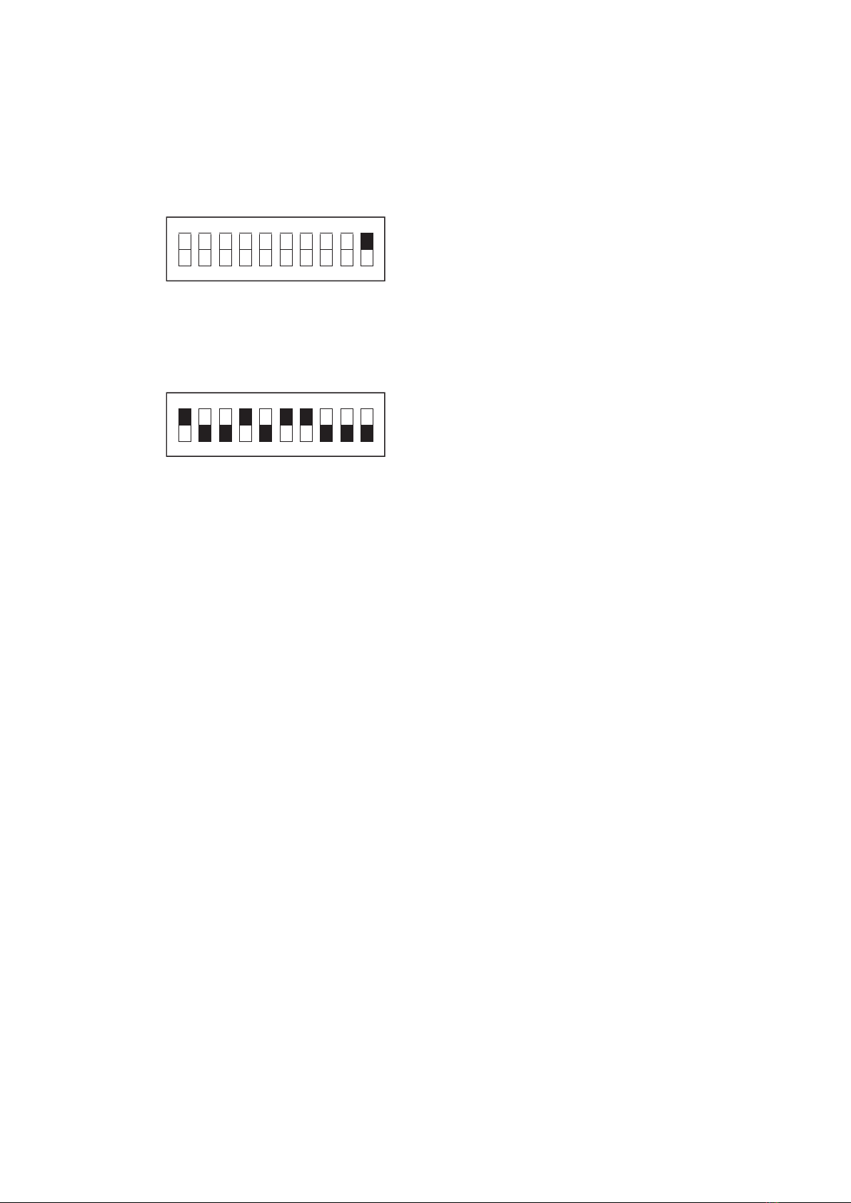
12 Programmeinstellung DIL-Schalter 10-polig - Programming of the 10-pole DIL-switch
- Programmation de la diode commutatrice (DIP):
Mit den DIL-Schaltern 1 bis 10 werden die Betriebs und
Programm Funktionen der MT-4 eingestellt.
„Der Auslieferungszustand ist eingerahmt“.
DIL-switches 1 to 10 are used for setting of operation modes of the MT-4.
„Initial state is framed“.
Les commutateurs DIP 1 à 10 permettent de régler les fonctions de service et de programmation du boîtier de
commande MT-4.
L´état de réglage à la livraison est encadré.´
12
Grundfunktion - Basic Function - Fonction standard:
Einstell-Betrieb
Start-up operation
Mode par réglage
Automatik-Betrieb
Auto Mode
Mode automatique
1 2 3 4 5 6 7 8 9 10
ON
1 2 3 4 5 6 7 8 9 10
ON
Reversier-Betrieb - Reverse Mode - Mode bidirectionnnel:
Tor bleibt in STOPP Position
Rolling door remains in STOP position
Porte reste en position STOPP
Auf-Befehl für 0,5 Sekunden
Up-signal for 0,5 seconds
Commande ouvert pendant 0,5 secondes
Auf-Befehl bis zur Endlage
Up-signal to the end position
Commande OUVERT jusqu´à la position finale
Tor bleibt in STOPP Position, Zusätzlich TEST der Leiste
Rolling door remains in Stop position, additionally TEST of the safety edge.
Porte reste en position STOP, TEST supplémentaire de la barre palpeuse
1 2 3 4 5 6 7 8 9 10
ON
1 2 3 4 5 6 7 8 9 10
ON
1 2 3 4 5 6 7 8 9 10
ON
1 2 3 4 5 6 7 8 9 10
ON

13
Schaltfunktion Relais 4 (230V) - Switching Funktion Relay 4
(230V) - Fonction de commutation relais 4 (230V):
Impuls 2 Sekunden nach einem AUF-Befehl
Impulse response 2 seconds after UP-command
Impulsion 2 secondes après une commande OUVERT
Dauer-Signal 2 Minuten nach jedem AUF-Befehl
Signal length 2 minutes after each UP-command
Signal permanent pendant 2 minutes après chaque commande OUVERT
Dauer-Signal solange das Tor offen ist
Flashing cycle while the door is open
Signal permanent tant que la porte est ouverte
Blink-Takt solange das Tor läuft
Flashing cycle while the door in operation
Feu clignotant durant l‘ouverture de la porte
1 2 3 4 5 6 7 8 9 10
ON
1 2 3 4 5 6 7 8 9 10
ON
1 2 3 4 5 6 7 8 9 10
ON
1 2 3 4 5 6 7 8 9 10
ON

14
OFF Ohne Verzögerung öffnen (voreingestellt)
ON Lichtansteuerung sofort nach Öffnungsimpuls
Verzögert öffnen (Einstellung für Frankreich)
OFF open without deceleration (preset)
ON Light pulse activation directly after opening impulse
Delayed opening (preset for France)
OFF Ouverture sans décélération
ON Sur commande allume éclairage
ouverture à retardement (pour la France)
1 2 3 4 5 6 7 8 9 10
ON
1 2 3 4 5 6 7 8 9 10
ON
Schaltfunktion Relais 5 (potentialfrei) Switching Function Relay 5
(potential-free) - Fonction de commutation relais 5 (potentiel libre):
ROT-Ampel Betrieb mit Vorwarnung bei automatischer Schließung
Red light operation with advance warning during automatic close-down
Feu ROUGE avec pré-avertissement en cas de fermeture automatique
Schaltsignal Tor OFFEN
Switch signal door OPEN
Signal de commutation porte OUVERTE
Schaltsignal Tor STÖRUNG
Switch signal door-BREAKDOWN
Voyant défaut porte
Test der Lichtschrankeneinheit LSC bei geschlossenem Tor
Test of the light barrier LSC while door is closed
Test la barrière photoélectrique lors de la fermeture de la porte
1 2 3 4 5 6 7 8 9 10
ON
1 2 3 4 5 6 7 8 9 10
ON
1 2 3 4 5 6 7 8 9 10
ON
1 2 3 4 5 6 7 8 9 10
ON
OFF Wartungszähler deaktiviert
ON Wartungszähler aktiv
(nach 2500 Zyklen blinkt die LED 6 in der Frontfolie)
OFF Maintenance scheduler deactivated
ON Maintenance scheduler activated
(after 2500 cycles the LED 6 in the front screen starts flashing)
OFF Compteur maintenance débranché
ON Compteur maintenance actif (aprés 2500 cycles la Led 6 clignote)
15
Auslieferungszustand
Initial state
Etat à la livraison
1 2 3 4 5 6 7 8 9 10
ON
1 2 3 4 5 6 7 8 9 10
ON OFF Normalbetrieb
ON Wartungszähler löschen
(zusätzlich NETZ AUS / NETZ EIN erforderlich)
OFF Normal operation
ON Delete the maintenance scheduler
(additionally POWER OFF/POWER ON required)
OFF Utilisation normal
ON Remise à zero du compteur maintenance
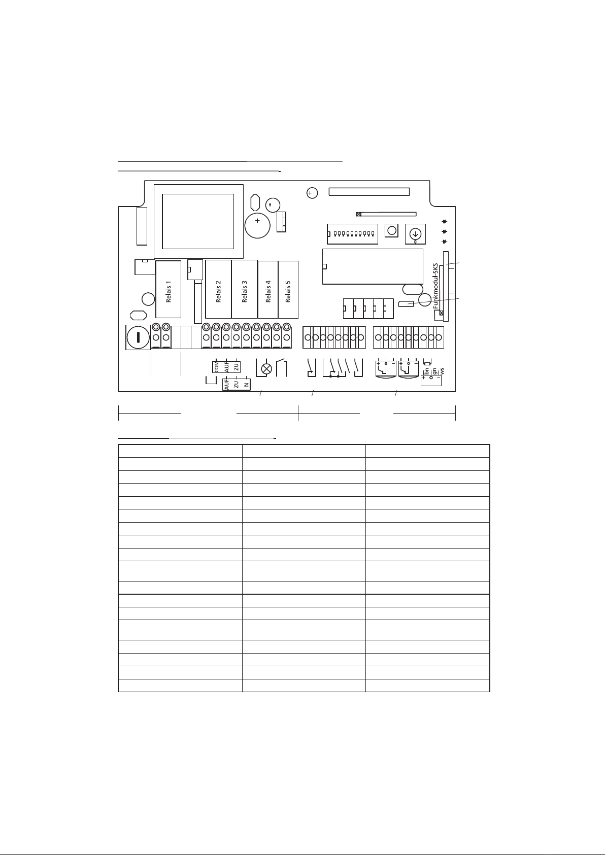
13 Layout Motorsteuerung MT- 4 - Layout Motor Control MT-4
- Schéma de circuit - boîtier de commande MT-4:
Programm Program Diode commutatrice
Tastatur Keyboard Clavier
„Lernen“ Taste „Configurating“ Button Enregistrement
Offenzeit Hold-open time Temps d´ouverture
Netz 230V AC Grid 230V AC Secteur 230V AC
potenzialfrei potential-free potentiel libre
Auf open ouvert
Zu close fermé
Not Stop Emergency Stop Arrêt d´urgence
Tasten Stopp / Auf / Zu Keys Stop / Up / Down Groupe d´interrupteurs ouverture /
fermeture / arrêt
Taste „Folge“ Key „Folge“ Bouton „Suite“
Lichtschranke Light barrier Barrière photoélectrique
Leiste Safety edge Barre palpeuse
automatische Steuerung der Garagen-
beleuchtung, Zeittakt = 2 Min
Automatic control for garage lights,
Time = 2 min
commande automatique de l´eclairage
du garage (minutage: 2 min)
Abrollsicherung Fall security Antichute
Tordurchfahrt in 0,5 m Höhe Crossing height 0,5 metres Hauteur de passage sous la porte à 0,5 m
Steckplatine Funk OSE Pin circuit board remote OSE Platine radio OSE
Jumper Funk OSE Jumper remote OSE Récepteur radio OSE
16
Trafo Programm
Tastatur
Lernen Zeit
Microprozessor
1 2 3
J1
PWR GN
SKS RT
Funk GE
F1
Max 4AT
L1 N PE
Netz
230V AC
Motor
230V
PE PE 1
Motor
potenzial-
frei
2 3 4 5 6 7 8 9
Relais 4
230V
Relais 5
potenzialfrei
Not-
stopp
Tasterblock
Stopp/Auf/Zu
Taste
Folge
LS 1 LS 2 SKS OSE
8,2 kR
10 11 12 13 14 15 16 17 18 19 20 21 22 23 24 25 26
1 10
230V 24V
autom. Steuerung der
Garagenbeleuchtung
Zeittakt = 2 Min
Abrollsicherung
Lichtschranke
Tordurchfahrt in
0,5 m Höhe
Steckplatine
Funk OSE
Jumper
Funk OSE
Übersetzung - Translation - Démultiplication :

14 LED Anzeige auf der Leiterplatte - LED-Display on the Circuit Card
- Affichage DEL sur la carte à circuit imprimé:
LED grün: POWER / Betriebsspannung ist in Ordnung
LED rot: LEISTE / Schaltleiste ist betätigt oder defekt
LED gelb: FUNK / Kontrolle für den Funkempfang und
Lernen / Löschen der Handsender
LED green: Power / operating voltage OK
LED red: Safety edge is active or faulty
LED yellow: radio remote control and
learn a remote / delete of the hand-held transmitter
DEL verte : POWER / Tension d´alimentation correcte
DEL rouge : LEISTE / Barre palpeuse active ou défectueuse
DEL jaune : FUNK / Contrôle de réception radio et
enregistrement / annulation des télécommandes
15 Frontfolie und LED Anzeigen - Front Pane and LED Display
- Panneau frontal et affichage DEL:
LED 1 grün: Betrieb
LED 2 rot: Störung
LED 3 gelb: Schaltleiste
LED 4 rot: Lichtschranke
LED 5 rot: Not-Stopp
(Störung Abrollsicherung, Stopptaster,
Lichtschranke, Einzugssicherung, LSC)
LED 6 gelb: Wartung
LED 1 green: in operation
LED 2 red: breakdown
LED 3 yellow: safety edge
LED 4 red: light barrier
LED 5 red: Emergency stop
(Failure fall security, stop button, light barrier, draw-in protection, LSC)
LED 6 yellow: Maintenance
DEL 1 vert: Service
DEL 2 rouge: Erreur
DEL 3 jaune: Barre palpeuse
DEL 4 rouge: Barrière photoélectrique
DEL 5 rouge: Arrêt d‘urgence
DEL 6 jaune: Entretien 17

16 LED Zustand / Störungs Tabelle - LED Status / Failure Index - Statut DEL / Tableaux erreurs:
18
LED 1 grün
LED 1 green
DEL 1 vert
LED 2 rot
LED 2 red
DEL 2 rouge
LED 3 gelb
LED 3 yellow
DEL 3 jaune
LED 4 rot
LED 4 red
DEL 4 rouge
LED 5 rot
LED 5 red
DEL 5 rouge
blinkt gleichmäßig
Flashes in regular intervals
Clignote à intervalle régulier
blinkt lange - AN, kurz - AUS
Long flash - ON, short - OFF
clignote à intervalle long (allumée)
puis court (éteinte)
leuchtet
Constant flash
allumée
blinkt gleichmäßig
Flashes in regular intervals
Clignote à intervalle régulier
blinkt schnell
Flashes quickly
clignote rapidement
blinkt schnell
Flashes quickly
clignote rapidement
leuchtet
Constant flash
allumée
blinkt gleichmäßig
Flashes in regular intervals
Clignote à intervalle régulier
blinkt gleichmäßig
Flashes in regular intervals
Clignote à intervalle régulier
blinkt gleichmäßig
Flashes in regular intervals
Clignote à intervalle régulier
leuchtet
Constant flash
allumée
leuchtet
Constant flash
allumée
leuchtet
Constant flash
allumée
blinkt gleichmäßig
Flashes in regular intervals
Clignote à intervalle régulier
leuchtet
Constant flash
allumée
blinkt schnell
Flashes quickly
clignote rapidement
leuchtet
Constant flash
allumée
blinkt schnell
Flashes quickly
clignote rapidement
blinkt schnell
Flashes quickly
clignote rapidement
leuchtet
Constant flash
allumée
leuchtet
Constant flash
allumée
Die Störungsanzeige kann durch Netz ausschalten oder durch Betätigung der Stopp-Taste
zurückgesetzt werden.
Fault indication can be disconnected via grid or be reset by the stop botton.
L´affichage des erreurs peut être éteint par mise hors tension ou remis à zéro par la touche STOPP.

19
LED 5 rot
LED 5 red
DEL 5 rouge
LED 6 gelb
LED 6 yellow
DEL 6 jaune
Zustand / Störung
Status / Failure
Etat / défaillance
Abhilfe / Lösung
Solution
Solution
Das Tor läuft
In operation
Porte activé
Alles in Ordnung
All in order
Fonctionnement normal
Die Offenzeit läuft ab
Hold-open time runs down
Temps d´ouverture terminé
Warnung. Das Tor läuft gleich an.
Warning. The door is starting up.
Attention, la porte s‘ouvre
Schaltleiste wurde 3 Mal angefahren
Safety edge initiated 3 times
Barre palpeuse activée 3 fois
Schaltleiste, Boden und B.-Schwelle auf Sauberkeit prüfen
Check the safety edge and the ground sill for cleanless.
Vérifier la barre palpeuse, la planéité du sol et la propreté.
Laufzeit von 3 Minuten überschritten
Run-time of 3 minutes exceeded
Durée de 3 minutes dépassée
Einstellung prüfen
Verify the setting
Vérifier l‘installation
Schaltleiste wurde angefahren
Safety edge initiated
Barre palpeuse activée
Schaltleiste prüfen, Hindernis beseitigen
Verify the safety edge, remove the obstacle
Vérifier la barre palpeuse e4t les connexions
Schaltleiste ist betätigt oder defekt
Safety edge initiated or faulty
Barre palpeuse activée ou défectueuse
Schaltleiste prüfen, Hindernis beseitigen
Verify the safety edge, remove the obstacle
Vérifier la barre palpeuse et les connexions
STOPP-Taste ist länger als 2 Minuten betätigt
STOP-button is held longer than 2 minutes
Touche arrêt urgence – activée pendant plus de 2
minutes
Not-Stoppeinrichtung prüfen, Klemmen 10/11 & 12/13
Verify the emergency stop, clamps 10/11 & 12/13
Vérifier les systèmes d‘arrêt d‘urgence et les connexions,
10/11 et 12/13
Taste ist länger als 2 Minuten betätigt
Button is held longer than 2 minutes
Touche activée pendant plus de 2 minutes
Klemmen 16/17 prüfen
Verify the clamps 16/17
Vérifier les connexions 16/17
Schaltleistentest war fehlerhaft
Switch panel test was incorrect
Test de barre palpeuse défectueux
Schaltleiste, Anschlüsse prüfen
Verify the safety edge and the connectors
Vérifier la barre palpeuse et les connexions
Lichtschranke unterbrochen
Light barrier disconnected
Cellulle photo-électrique en défaut
Hindernis beseitigen, Einstellung prüfen
Remove the abstacle, check the setting
Vérifier le fonctionnement et les connexions de la
cellule photo-électrique
Not-Stopp ausgelöst (Störung Abrollsicherung / Taster)
Emergency stop released (Failure fall security / switch key)
Arrêt d‘urgence déclenché ( défaut antichute/ bouton)
Abrollsicherung prüfen und eventuell tauschen
Verify - possibly replace - the fall security
Vérifier l‘antichute et si besoin le changer
blinkt lange - AN, kurz - AUS
Long flash - ON, short - OFF
clignote à intervalle long (allumée)
puis court (éteinte)
Batterie der Funk-SKS wird schwach
Low battery capacity of the radio-SKS
La batterie de la barre palpeuse radio est faible
Batterie der Funk-SKS tauschen
Replace the battery of the radio-SKS
Changer la pile de la barre palpeuse
blinkt gleichmäßig
Flashes in regular intervals
Clignote à intervalle régulier
Wartungszähler überschritten
Service interval exceeded
Le nombre de cycles pour la maintenance est dépassée
Wartung durchführen & Zähler zurücksetzen, Netz ein/aus
Provide service & set back the counter, Power on/off
Effectuer la maintenance et remise à zéro
leuchtet
Constant flash
allumée
Batterie der Funk-SKS ist leer
Battery of the radio-SKS is discharged
La pile de la barre palpeuse radio est vide
Batterie der Funk-SKS tauschen
Replace the battery of the radio-SKS
Changer la pile de la barre palpeuse
Other Deltadoors Gate Opener manuals


Popular Gate Opener manuals by other brands

quiko
quiko Titano QK-T4000 Use and maintenance manual

Linear
Linear SG installation guide

IQ Gate Systems
IQ Gate Systems IntelliSwing IQ-500-S Installation and instruction manual

GFA
GFA 10003903 10012 installation instructions

Extel
Extel Umii XC500 quick start guide

fadini
fadini FIBO 300 installation manual


