Wallbeds Northwest ENDURA II CABINET User manual

Thank you for purchasing your Wall Bed from Wallbeds Northwest.
When purchasing a complete "Endura II DIY Kit," most of the manufacturing work is
already done for you. However, you will need to drill a few holes and possibly cut
moulding on site (if your project comes with moulding), proper tools, and the ability to
assemble the unit. Please carefully read the instructions and pay special attention to the
safety guidelines
STUD FINDER
LEVEL
LADDER
ELECTRIC DRILL
SLOTTED SCREW DRIVER
PHILLIPS HEAD SCREWDRIVER
3/16" DRILL BIT
NOTE! PLEASE READ THROUGH THE DIRECTIONS BEFORE YOU PURCHASE ANY OF THE
FOLLOWING ITEMS. SOME ITEMS MAY NOT BE NEEDED.
ENDURA II CABINET PLANS AND INSTRUCTIONS
Wallbeds Northwest
**Note: Some Pre-drilling is necessary for
Confirmat Screws - 3/16 Bit.
NOTE!
If you have ordered a unit that has Crown &
Base Moulding it does not come pre-cut.
You will need to cut it to fit onsite and will
need a chop saw and nail gun or hammer
with finishing nails.
CRESCENT WRENCH
Tools Needed
TAPE MEASURE
Wallbeds Northwest
17646 NE 65th St.
Redmond, WA 98052
1-425-284-6692
www.wallbedsnw.com
NEEDLE NOSE PLIERS
Various Bits - #2Square
#2 & #3 Phillips
MITER SAW-FOR MOULDING
FINISHING NAILS
HAMMER
NAIL GUN OR
HEX Wrenches

80 Wood Screws 1 1/4"
PAGE 2
ENDURA II PARTS LIST
1 Right & 1 Left Endura II Mechanism
Right & Left Legs
200 - #10 Nickel Screws -5/8"
8 Hex Head Machine Screws
PARTS LIST
10 Wood Screws 3"
10 Rafix Connector Bolt
10 Rafix Connector
28 Confirmat Screws
40 "L" Brackets
NOTE; There are extra parts provided for some of the following.
8 "Z" Brackets

PAGE 3

PAGE 4
87
82
82
16
16
16
85 7/8
80 7/8
80 7/8
66
60
45
Queen
Full
Twin
Open
Depth
Height
Width
DImensions
For Melamine and/or Thermofoil Projects only;
Please note the addition of an Unfinished Plywood Top
Stretcher . This is for extra strength when attaching the
Wallbed Cabinet to the Wall through the Top Back
Stretcher. After attaching the Wallbed to the Wall use the
Matching Finished Top Back Stretcher to cover it. Use
screws, glue, or finishing nails.
Assembled View of Endura II Wallbed Cabinet
16" Deep Cabinet will accommodate a 10" thick Mattress

Lay the door panels on the carpet or a nonabrasive surface. Set the head, foot, side rails, and
slats in their approximate positions. You will need Confirmat screws, 2 1/2" “L” brackets and
5/8" Nickel wood screws.
THE PLATFORM ASSEMBLY
CABINET
SECTION
Assemble the head rail and the foot rail to the side rails (rail assembly) with 2 Confirmat
screws on each corner. The side rail ends butt up to the head rail and the foot rail butts up to
the side rails. See diagram 4A. Drill a 3/16" pilot hole into all the end panels as the confirmat
screws are not self-tapping.
HEAD RAIL
FOOT RAIL
SIDE RAIL
TOP VIEW
FOOT RAIL
HEAD RAIL - H
SLATS - I
SIDE RAIL -F
DOOR PANELS - A
SIDE RAIL -F
Set the Cross Slats horizontally as shown with one butted to the head rail and the ONLY
SHORT ONE butted to the foot rail with the other two (or three) evenly spaced. Attach the
“rail” assembly to the slats with the “L” brackets as shown.
#1
#2
#3
DIAGRAM - 4A
Head rail
Side rails
Foot rail
PLATFORM
SECTION
Diagram - A
PAGE 5
The platform is the part of the wall bed that holds the mattress and is pulled down from the wall. Start by
assembling the platform section. The following example is for a full size bed. Assembly for twin and
queen is the same with the exception being that the twin uses one door panel.
Note! Do Not yet Attach the Bed Face Panels to the Platform Frame.

Attach “L” Brackets as shown using 5/8" Nickel wood screws. Use only 5/8" screws when assembling the
head, side and foot rails.
HEAD
FOOT
Square the “rail” assembly on top of the Door
Panels and attach 8 “Z” brackets as shown to
ONLY the Door Panels. Do not attach the "Z"
Brackets to the Cross Slats at this time. You will be
removing the Platform Assembly from the Door
Panels in order to attach it to the Wallbed Cabinet.
You will "hang the Door Panels on the Platform
Assembly near the end of the installation. The head
rail sits flush with the edge of the door panels and
the side rails should be centered left to right with the
door panels.
#4
Use 5/8" Nickel wood screws to
attach “L” brackets to the slats.
Flush
"Z" Bracket
5/8" Nickel Wood Screw
#5
Remove the Locking Pins on the Left and Right Mechanisms as shown. A flat head screwdriver works best.
Separate the two sections and attach the Mounting Plate to the bed vertical with the 5/8" Nickel wood Screws
as shown.
Bed Vertical
Platform
Assembly
Attach the Spring Section of the Mechanism
to the outside of the Platform assembly with
the Hex Head Machine screws as shown.
#6
Spring Section
of Mechanism
Front of Vertical
Attach with 5/8"
Nickel Screws
Machine
Screws
Door Panels
PAGE 6

Pre-Drill a 3/16" Dia. x 1 1/2" deep Pilot Hole
on all pieces requring Confirmat Screws;
Cabinet Top, Stretchers,
Bottom Stretcher,
Side Rails, & Foot Rail.
THE CABINET ASSEMBLY
#1
PAGE 7
The cabinet assembly is the section that is attached to the wall
and is what the platform folds into.
Assemble the cabinet face down on the floor. Attach the Top Back Stretcher to the Cabinet Top
and Bottom Back Stretcher to the Bottom Stretcher using Confirmat Screws. Attach the Cabinet
Top and Bottom Stretcher to the Verticals with confirmat screws. Attach the Angled Middle
Stretcher to the Bed Verticals with the Rafix Connectors. The Stretchers are mounted in between
the Verticals as shown below. The Top Front Stretcher should not be mounted until the Platform
assembly is installed. When using confirmat screws, a 3/16" pilot hole needs to be drilled
through the verticals and into the horizontal parts.
ENDURA II CABINET
CABINET TOP
VERTICALS
Confirmat screws should be
used in these locations.
Front
Back
c
Cabinet Top mounts flush
with the tops of verticals.
FRONT VIEW
VERTICAL
SIDE VIEW
BOTTOM STRETCHER
Mounts flush with the
bottom and back of verticals
( or can be raised up 1/4" to
help clear carpeting).
VERTICAL
All back stretchers are mounted flush
with the back and between the
verticals. For Melamine projects mount
the Unfinished Plywood Top Back
Stretcher to the Cabinet Top. After
installing the cabinet to the wall, cover
the Unfinished Plywood Stretcher with
the matching finished one. Mount the
Middle Back Stretcher using the Rafix
Connectors.
TOP BACK STRETCHER
Angled Middle
Back Stretcher
BOTTOM BACK
STRETCHER
Bottom is edge
banded 1 - Long
Confirmat Screw
Rafix Connector Parts
Rafix Connectors should be
used in these locations.
R

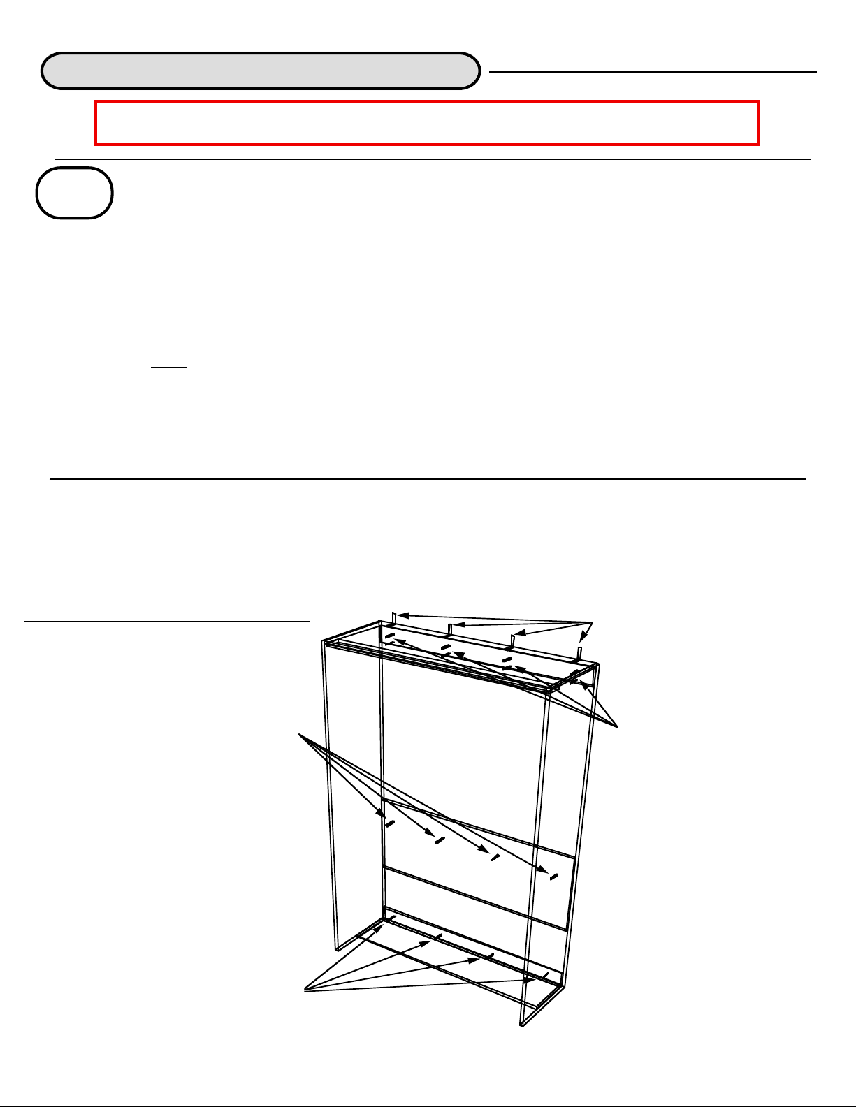
Position the cabinet against the wall where it is to be mounted. Make sure that it is square.
Locate all the studs that are behind the cabinet. Mount the cabinet to wood studs with heavy
duty 3"-4" wood screws. It is helpful to set the platform in the cabinet to check for square
before mounting all the "L" brackets. To do this, attach 2 - "L" brackets to the top of the cabinet
- one on the left and one on the right and secure to the wall with just 1 screw on each side.
Follow the instructions below for attaching the platform and close the bed to check that
everything is square. (Caution! Do not operate the bed until it is completely secured to the
wall.) If it is, then secure firmly into all studs possible. If it not, then pull the bed out and either
reposition the top of cabinet left or right into the studs or shim the cabinet as needed. The wall
bed must be mounted with large heavy duty screws with the "L" brackets on top of the Top
Stretcher or through the Top Back Stretcher, or both. 2 to 4 additional screws should be put
into each stud through the Top Back Stretcher, the Middle Stretcher(Except for the Angled
Middle Stretcher) and the Bottom Stretcher. A twin should be attached to no less than two
studs, full and queen should be three studs or more. Securing the Bed Cabinet to any side
cabinets is also recommended for additional safety. Each of the Side Cabinets - if any - should
also be attached to the studs in the wall in the same way as the Bed Cabinet.
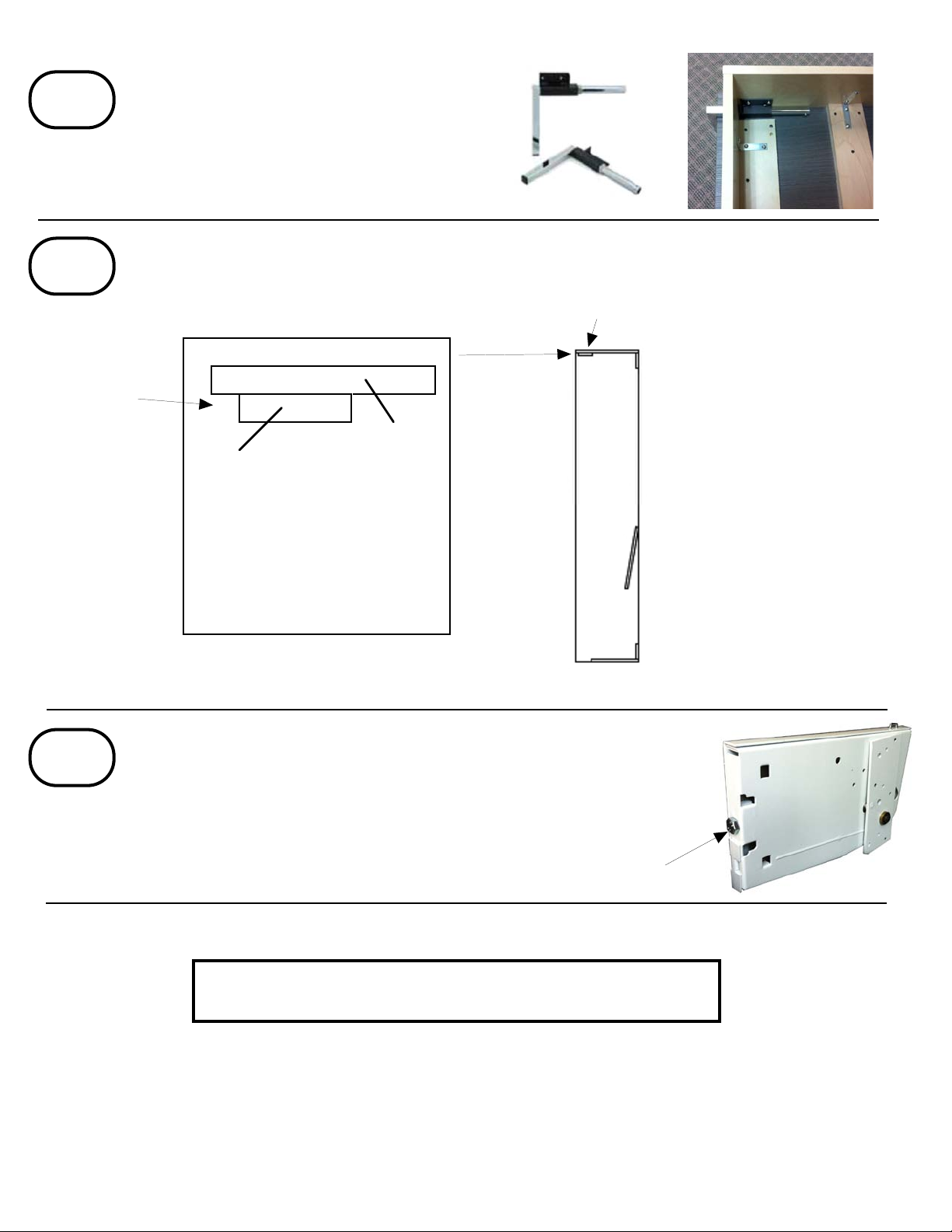
If you have a wall that does not have wood studs, then you must attach the Bed Cabinet
securely with the appropriate Anchors.
Installing the Cabinet to the Wall
IMPORTANT! DO NOT MOUNT WALL BED INTO DRY WALL ONLY. IT
MUST BE SECURELY FASTENED INTO ALL AVAILABLE STUDS.
#1
!Caution!
Mount 1-2
Screws through
the Middle
Stretcher mount with
Screws through
the Top Back
Stretcher
Mount 1-2 Screws through
the Bottom Back Stretcher
Mount "L" Brackets
into every stud
behind the bed
Or
Optional:
(Not recommended with
Angled Middle Stretcher)
PAGE 8
Proper installation & Usage procedures must be followed to prevent
possible risk of injury or death! Wallbeds must be mounted properly and
securely to the studs in the wall as per instructions. When operating the
wallbed make sure that there is no one in or near the unit. When opening the
wallbed make sure there is no one under it and when closing the wallbed
make sure that all hands and extremities are clear of any "pinch" points.

INSTALLING PLATFORM TO CABINET
Set the Platform Section upright in front of the Wallbed Cabinet.(Note:The Front Door Panels should not be
attached at this point). Slide the Platform into the Cabinet evenly making sure to align the slots on the
mechanism as shown.
PAGE 9
#1
#2
#3
Caution!!! Be careful not to drill through the Bed Door Panels. If you are using RIgid Thermofoil Doors do
not put screws into both holes of the "L" Bracket when attaching Door Panel Faces. Usually the hole
closest to the side rail should not be used. It is best to measure the face to determine which holes to avoid.
Mount 1-2
Screws through
the Middle
Stretcher mount with
Screws through
the Top Back
Stretcher
Mount 1-2 Screws through
the Bottom Back Stretcher
Mount "L" Brackets
into every stud
behind the bed
Or
Slot
Slide forward evenly
Lock into place
Replace the Locking Pin to secure the mechanism in place. Needle Nose or similar pliers help inthis process.
Hang the Door Panels on the Cross Slats as shown and secure using 1 1/4" Wood Screws as shown in the
diagram. After Securing the Door Panels to the Platform the "Z" Brackets can be removed.
"Z" Brackets
Door Panel
1 1/4"
Wood
Screws
"Z" Brackets

#4
Attach the legs to the platform with 5/8" Nickel
screws provided as shown. Unscrew the Set
Screw that keeps the leg from pulling completely
out. Mount the Brackets throught the notches in
the Footrail, slide the legs back in and reinsert the
Set Screw.
SET THE TOP FRONT STRETCHER
3/4"BACKFROM THEFRONTOF THE
CABINET FOR DOOR PANELS THAT
ARE 3/4". IT IS THEPIECE THAT THE
PLATFORM CLOSES AGAINST.
SIDE VIEW
UPPER SECTION OF CABINET
CABINET TOP
TOP FRONT STRETCHER
EDGE BANDED 2 LONG
If you have any questions, please
contact us at Wallbeds Northwest Inc.
17646 NE 65th St • Redmond, WA 98052
Phone (425) 284-6692 Fax (425) 284-6695
PAGE 10
#5
Attach the Top Front Stretcher using 1 1/4" Wood Screws. Set the Stretcher back the same distance as the
thickness of the Bed Face(Door Panels), which is usually 3/4". If doing a Shaker design it will be 1" from the front.
Bed Cabinet Side View
Front
Back
3/4" Setback
is typical
Attach 5 - 1 1/4" Screws from the Top
Thank you for purchasing your wallbed from Wallbeds Northwest
Adjust the Mechanism if necessary. There is already a lot of
tension on the bed, but if it is a heavier bed or you have a heavy
mattress, you can adjust the mechanism and make the bed
easier to operate. Use a 17mm open end wrench or crescent
wrench to tighten the nut at the back of the mechanism. You can
only tighten the mechanism, not loosen it.
#6
Rear View - Adjustment Nut
Table of contents
Other Wallbeds Northwest Indoor Furnishing manuals
Popular Indoor Furnishing manuals by other brands

Balt
Balt Posture Perfect Chair 34571 manual

Homelegance
Homelegance 5803RF-36 Assembly instruction

THB
THB Air 1P 80cm Tipper Slim Gourmet Kitchen Assembly instructions

HAMPTON BAY
HAMPTON BAY GENEVA WOVEN FRS60704-ST Use and care guide

Jahnke
Jahnke CGL C 140 AEU manual

STILFORD
STILFORD STPCT12WEK Assembly instructions

SUNON
SUNON T218 installation manual

IKEA
IKEA Hemnes 6-drawer white stain Assembly instructions

Cooper Lighting
Cooper Lighting Lumark AVID Series brochure

Mountrose
Mountrose 00227 Assembly and operating instructions

Homelegance
Homelegance 1104BR-3 Assembly instruction

Baby Relax
Baby Relax DA7432B2-W instruction manual