Wallbeds Northwest ENDURA User manual

Thank you for purchasing your Wall Bed from Wallbeds Northwest.
If you have purchased a complete "Endura DIY Kit," then much of the work is already done
for you. Please skip to assembly instructions. Note that some of the hardware may be
slightly different than what is shown in the plans and instructions and is already included.
The following instructions are for building and installing a complete Endura Wall Bed cabinet and mechanism
purchased from Wallbeds Northwest. These instructions are designed for an inexperienced builder to be able
to put the Endura Wallbed together. If you are an experienced builder, then you may want to do some
modifications or put it together with different materials.
Start by cutting and edge-banding all the pieces shown on the ENDURA CUT LIST in the size and material of
your choice. The dimensions on the cut list are the finished sizes. If you are using edge-banding thicker than
normal tape edge-banding, then youʼll need to compensate in your measurements. Solid wood is certainly
okay to use but is not recommended for the door panels or verticals because of possible warping.
If you are building everything yourself you will need most of the following hardware* and tools;
100 - 11/4" WOOD SCREWS
110 - 3/4"" WOOD SCREWS (Nickel)
34 - 2" CONFIRMAT SCREWS
8 to 12 - 3" DRY WALL SCREWS
26 - 2 1/2" “L” BRACKETS
STUD FINDER
LEVEL
LADDER
ELECTRIC DRILL
SLOTTED SCREW DRIVER
PHILLIPS HEAD SCREWDRIVER
DRILL BITS** - VARIOUS SIZES
GETTING STARTED
WOOD GLUE
LARGE WOOD CLAMPS
CAUTION! PLEASE READ THROUGH THE DIRECTIONS BEFORE YOU PURCHASE ANY OF THE
FOLLOWING ITEMS. SOME ITEMS CAN BE SUBSTITUTED WITH DIFFERENT MATERIALS.
ENDURA CABINET PLANS AND INSTRUCTIONS
Please make sure you have the capability and tools required in order to be able to properly put the door panel
sections together when building a full or queen (twin size can be 1 door panel). The door panels can be joined
down the center or you can choose to leave a 1/8" reveal. If cutting yourself, you will want to make sure that the
seam is perfect. You can also cover the seam with different mouldings for decoration.
IMPORTANT
Wallbeds Northwest
* If you purchased a complete Wall Bed Mechanism and Cabinet, the hardware is included.
**Note: Some Pre-drilling is necessary for Confirmat Screws - 3/16 Bit.
CRESCENT WRENCH
TOOLS
HARDWARE
TABLE SAW
TAPE MEASURE
COUNTERSINKS
SOCKET SET
Wallbeds Northwest
17646 NE 65th St.
Redmond, WA 98052
1-877-327-4543
www.wallbedsnw.com
If you have purchased a complete Wallbed Cabinet, then go directly to the Assembly and Installation sections.
8 - RAFIX CONNECTORS

PAGE 2
ENDURA PARTS LIST
When you purchase an ENDURA WALL BED MECHANISM from Wallbeds Northwest, you will receive
the parts listed below and the instructions that follow. If you purchase an ENDURA WALL BED
MECHANISM and CABINET, then you will receive the parts listed below, instructions, the cabinet materials
and the hardware to assemble it. You will still need the proper tools to assemble the wall bed.
1 RIGHT AND 1 LEFT SIDE ENDURA MECHANISM
RIGHT AND LEFT SIDE LEGS
1 LEG CONNECTOR -WHITE ROD
8 - MECHANISM MOUNTING BOLTS
4 PLASTIC COVER MOUNTING SCREWS
1 RIGHT AND 1 LEFT PLASTIC MECHANISM COVERS
2 PLASTIC LEG CONNECTOR INSERTS
2 LEG CONNECTOR SCREWS
8 - LEG MOUNTING SCREWS
6 - MECHANISM MOUNTING WASHERS
8 - MECHANISM MOUNTING NUTS
2 EXCENTRIC WASHERS
16 SPRINGS - FULL
14 SPRINGS - TWIN
18 SPRINGS - QUEEN
6 PLATFORM MOUNTING BOLTS
6 PLATFORM MOUNTING WASHERS
6 PLATFORM MOUNTING NUTS
PARTS LIST

PAGE 3

PAGE 4
91
86
86
16
16
16
85 7/8
80 7/8
80 7/8
65 7/8
59 7/8
44 7/8
Queen
Full
Twin
Open
Depth
Height
Width
DImensions
For Melamine and/or Thermofoil Projects only;
Please note the addition of an Unfinished Plywood Top
Stretcher . This is for extra strength when attaching the
Wallbed Cabinet to the Wall through the Top Back
Stretcher. After attaching the Wallbed to the Wall use the
Matching Finished Top Back Stretcher to cover it. Use
screws, glue, or finishing nails.

6 1/16"
11"
13/16"
7/8"
Ø 5/16" Ø 5/16"
HEAD RAIL
SIDE RAIL
18 1/2"
3/4"
Ø 5/16"
THE PLATFORM ASSEMBLY
CABINET
SECTION
Lay the door panels on the carpet or a nonabrasive surface. Set the head, foot, side rails, and
slats in their approximate positions. You will need approx. 30 - (2 1/2" or 3") “L” brackets,
approx. 100 - 3/4" wood screws, 1 box - 1 1/4" wood screws and 8- CONFIRMAT screws.
Pre-drill side rails with 5/16" bit as shown. ( If you have a DIY Kit skip this step).
If the side rails are not pre-drilled and are drilled after assembling the head rail,
make sure you compensate for the 3/4" thickness of the head rail.
#1
#2
NOTE! TWIN SIZE MAY REQUIRE FEWER MATERIALS FOR SOME ITEMS.
Head rail
Side rails
Foot rail
PLATFORM
SECTION
Diagram - A
Side view of door panels
with a 1/8" spline-(Optional)
Diagram 1A
PAGE 5
3/4”
#1
#2
#3
MOUNTING BOLT HOLES
Caution! Be careful not to drill through the face of the Door Panels -
especially when using Rigid Thermofoil Door Panels
The platform is the part of the wall bed that holds the mattress and is pulled down from the wall. Start by
assembling the platform section. The following example is for a full size bed. Assembly for twin and
queen is the same with the exception being that the twin uses one door panel.

Assemble the head rail and the foot rail to the side rails (rail assembly) with 2 CONFIRMAT
screws on each corner. The side rail ends butt up to the head rail and the foot rail butts up to
the side rails. See diagram 4A. Use 1/2" inch wood screws to fasten one (or two) “L”
brackets to reinforce each corner. If you have purchased a DYI Kit bed, then you will need to
drill a 3/16" pilot hole into all the end panels as the confirmat screws are not self-tapping.
HEAD RAIL
FOOT RAIL
SIDE RAIL
TOP VIEW
FOOT RAIL
HEAD RAIL - H
SLATS - I
SIDE RAIL -F
DOOR PANELS -A
SIDE RAIL -F
Set the slats horizontally as shown with one butted to the head rail and one butted to the foot
rail with the other two evenly spaced. Attach the “rail” assembly to the slats with the “L”
brackets as shown. Attach the “rail” assembly and slats to the door panels with the “L”
brackets as shown.The head rail sits flush with the edge of the door panels and the side rails
should be centered with the door panels. There should be a 1 1/16" lip on each side. Use 1
1/4" wood screws where the “L” brackets sit on top of the slats and use only 1/2" wood
screws when mounting "L" brackets directly into the door panel. CAUTION!! If you
are using Rigid Thermfoil Door Panels you must be careful not to drill through the
recessed areas of the doors. Measure the front of the panels and note where it is
recessed and do not put screws in that area. (See note below).
#3
#4
DIAGRAM - 4A
“L” Bracket placements using 1/2" wood screws. Use only 1/2" screws on all
corners when screwing head, side and foot rails together. Caution!!! If you
are using RIgid Thermofoil Doors, do not put screws into both
holes of the "L" Bracket when attaching Door Panel Faces.
Usually the hole closest to the side rail should not be used. It is
best to measure the face to determine which holes to avoid.
VIEW OF ASSEMBLED PLATFORM
Use 11/4" wood screws when screwing in “L”
brackets through slats and into the door panels.
Use only 11/4" wood screws when screwing in the slats to the door panels.
Make sure to place screws through slats into bed face as shown.
SLATS
HEAD
FOOT
HEAD
FOOT
PAGE 6
NOTE!
Caution!

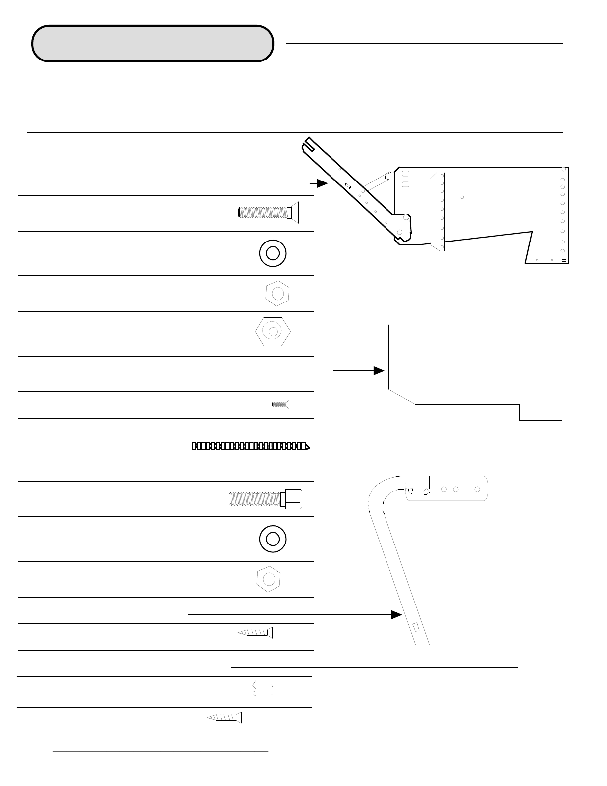
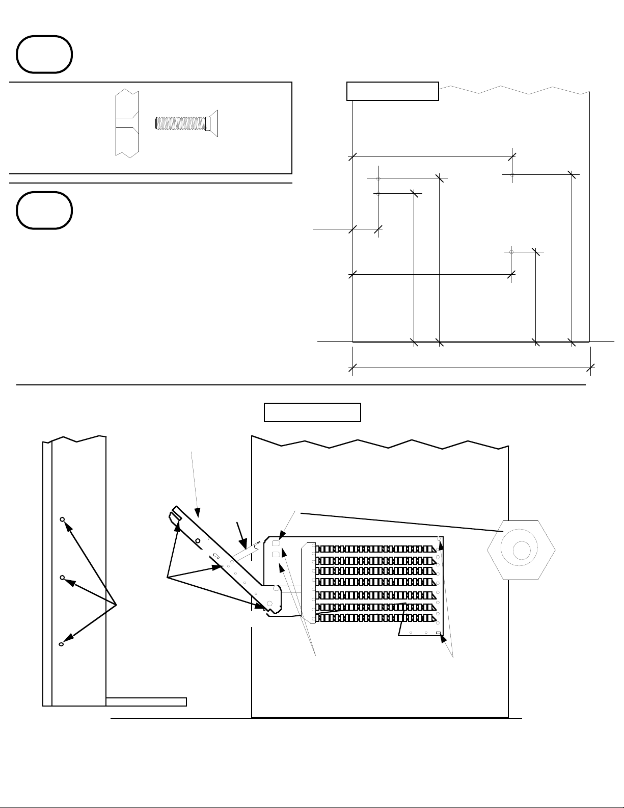
You will need to Pre-Drill 3/16" Dia. x 1 1/2"
Deep Pilot Hole on all pieces requring
Confirmat Screws;
Cabinet Top,
Bottom Stretcher,
Side Rails, & Foot Rail.
THE CABINET ASSEMBLY
#1
PAGE 7
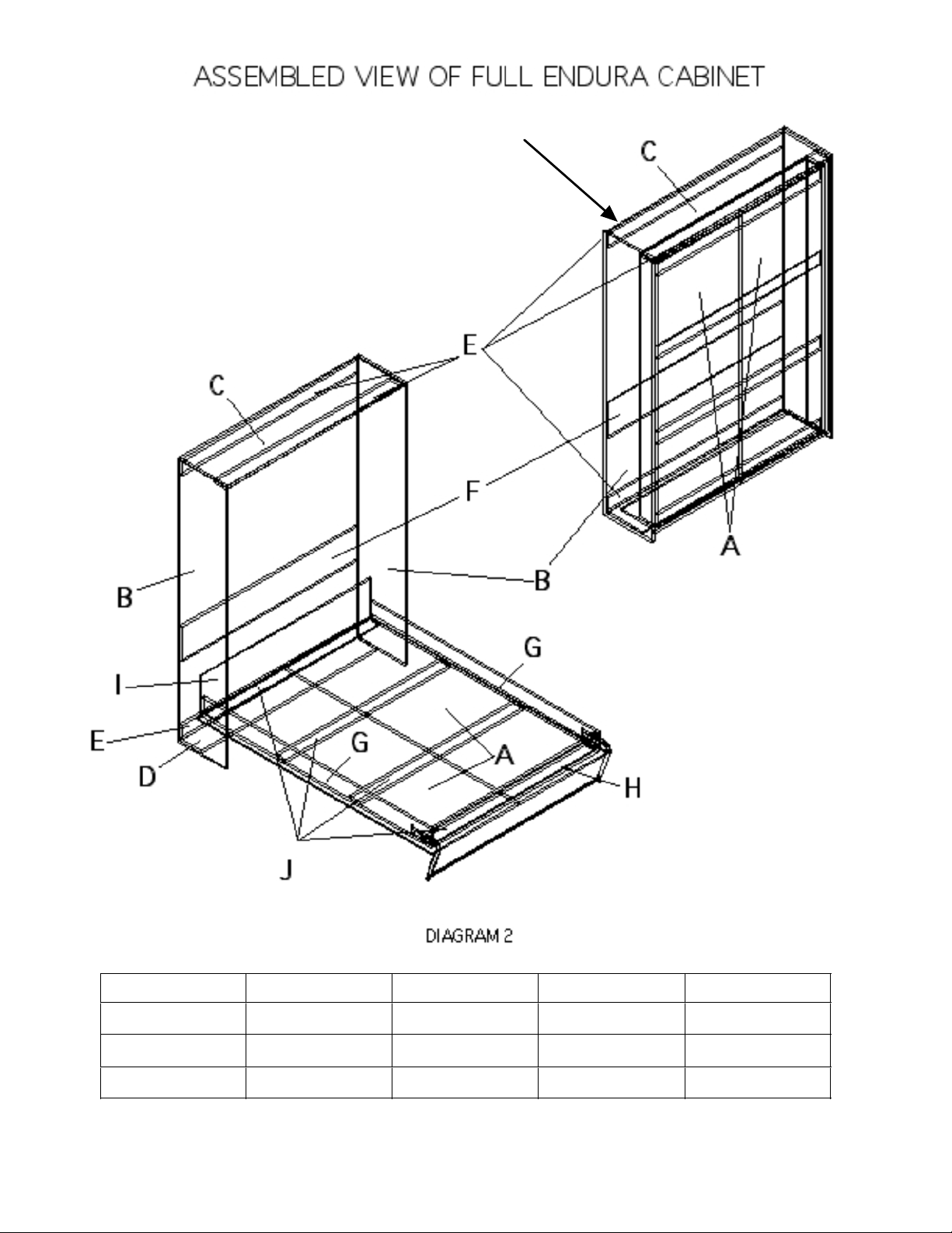
The cabinet assembly is the section that is attached to the wall
and is what the platform folds into.
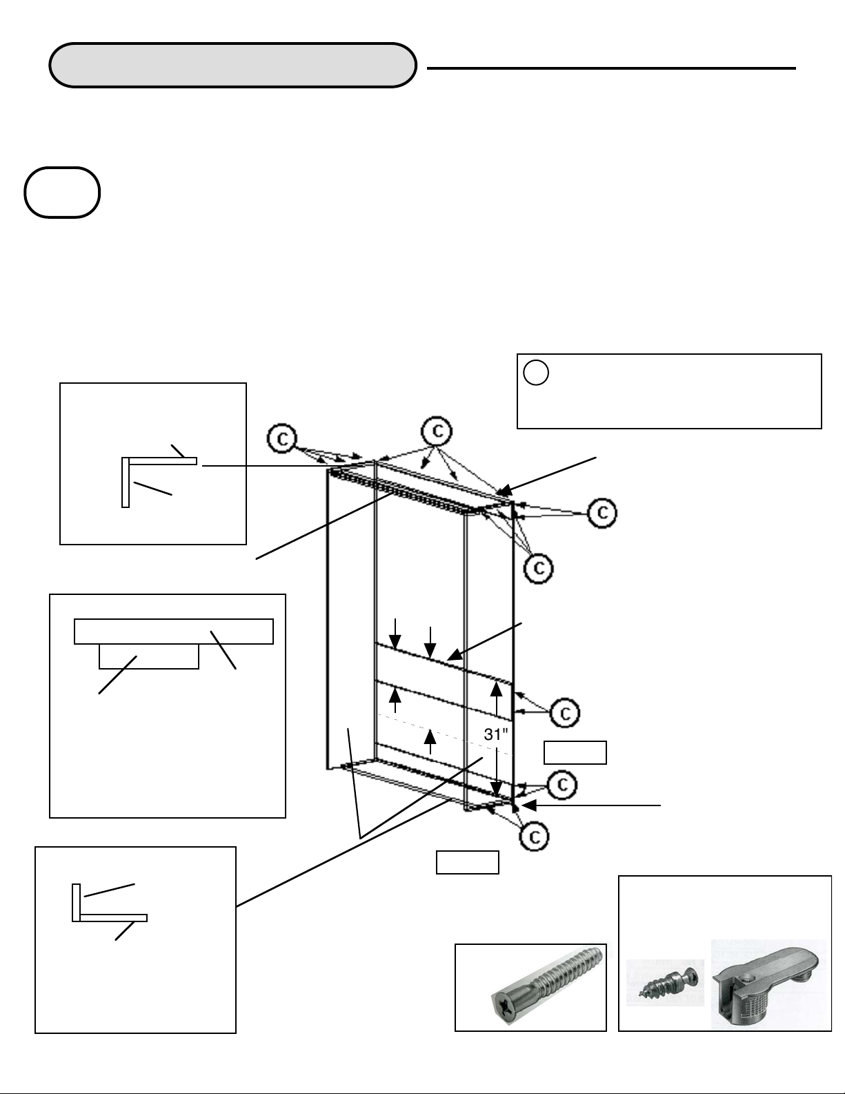
Assemble the cabinet face down on the floor. Attach the CABINET TOP and the BOTTOM
STRETCHER to the VERTICALS with confirmat screws. Confirmat screws are recommended,
but can be substituted with “L” brackets and/or wood screws. The Stretchers are mounted in
between the verticals as shown below. The Top Front Stretcher should be mounted with 1 1/4"
screws from the top of the Cabinet Top rather than confirmats from the sides of the Verticals.
When using confirmat screws, you should drill pilot holes through the verticals and into the
stretchers and then screw in the confirmats. The CONFIRMAT screws accept plastic plugs in
manymatchingcolors.See yourlocalhardwaredealerforinformationon this. If using“L”brackets,
then put as many on as necessary - all corners and every 24” to 36”. Tilt the cabinet upright and
position it against the wall.
ENDURA CABINET
CABINET TOP
VERTICALS
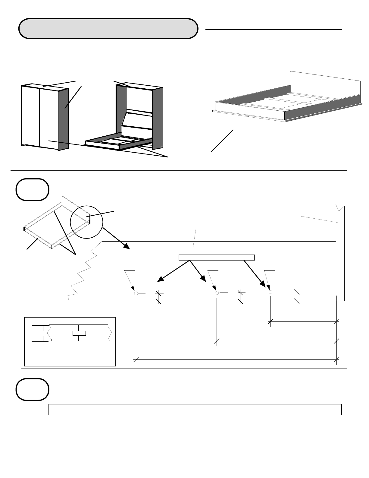
CONFIRMAT screws should be
placed in these locations. (Kit
Beds may substitute Rafix
Connectors in some areas).
Front
Back
c
Cabinet Top mounts flush
with the tops of verticals.
FRONT VIEW
VERTICAL
SIDE VIEW
BOTTOM STRETCHER
Mounts flush with the
bottom and back of verticals
( or can be raised up 1/4" to
help clear carpeting).
VERTICAL
All back stretchers are
mounted flush with the back
and between the verticals.
Mount the Unfinished Plywood
Top Back Stretcher to the
Cabinet Top. After installing
the cabinet to the wall, cover
the Unfinished Plywood
Stretcher with the matching
finished one. Mount the Middle
Back Stretcher 31" from the
floor. If you have ordered the
unit with a Sloping Headboard
the Middle Stretcher will be 20"
instead of 10". Mount the
Bottom Back Stretcher on top
of the Bottom Stretcher.
TOP BACK STRETCHER
MIDDLE BACK
STRETCHER
BOTTOM BACK
STRETCHER
31"
Top is edge banded 1 - long.
Middle Stretcher
is edge banded
1 - long.
Bottom is edge
banded 1 - Long
SET THE TOP FRONT STRETCHER
3/4" BACKFROM THE FRONT OFTHE
CABINET. IT IS THEPIECE THAT THE
PLATFORM CLOSES AGAINST.
SIDE VIEW
UPPER SECTION OF CABINET
CABINET TOP
TOP FRONT STRETCHER
EDGE BANDED 2 LONG
TOP FRONT STRETCHER
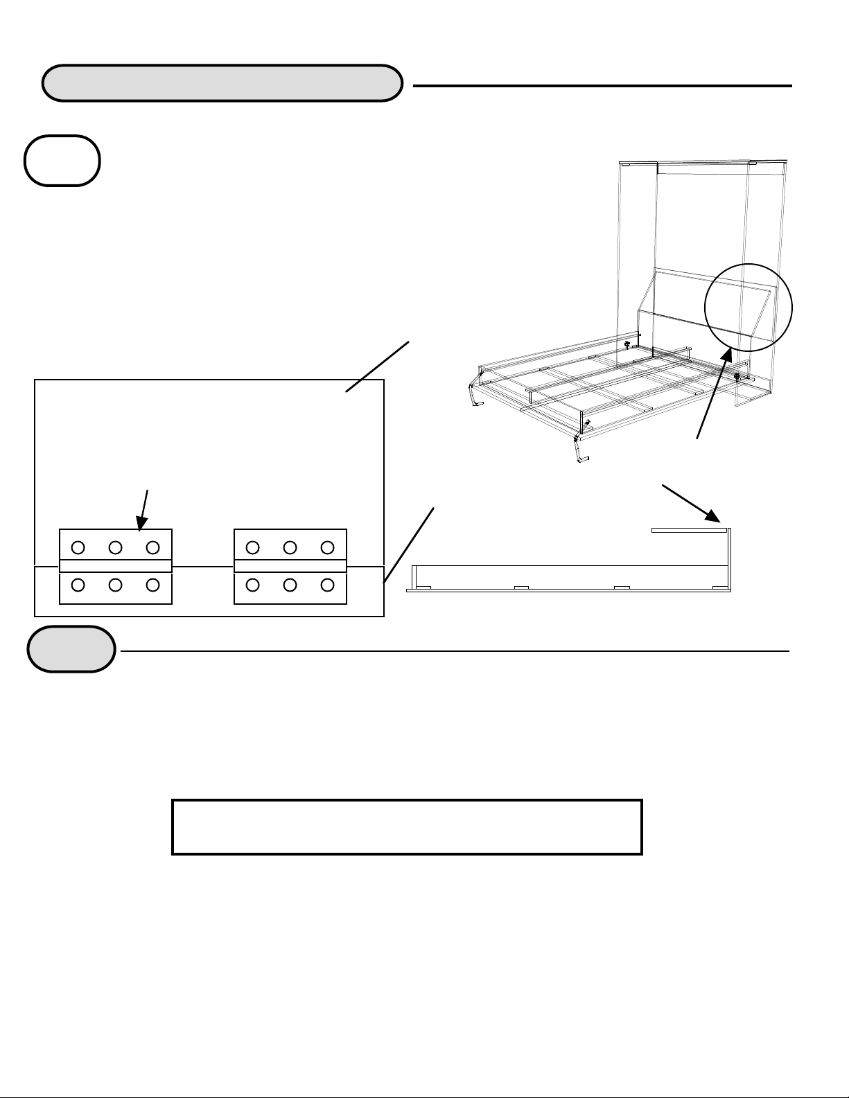
Note: If you have purchased a "Complete Wallbed" then some of the
connectors will be changed to a Rafix Connector (see below).
Confirmat
Screw
Rafix Connector Parts
come with purchase of
complete wallbed units
10"
20"

FLOOR FRONT BACK
VERTICAL
MOUNTING BOLT HOLES
TENSION BAR
PLATFORM
MOUNTS
#1
#3
#1
#2
#3
#2
EXCENTRIC WASHER PLACEMENT
FLOOR
21"
FRONT BACK
VERTICAL
13 5/32"
14 17/32"
2 1/4"
14"
7 15/16"
14 27/32"
14 1/16"
#2
PAGE 8
Drill 4 holes in each Vertical with a 5/16th inch bit as diagramed below. Countersink each hole from
the outside of the cabinet to accommodate the bolts that hold the Endura mechanism.
NOTE! If you have a DIY Kit then skip this step
DIAGRAM 2A
DIAGRAM 3A
WALL
PLATFORM
SIDE VIEW
Mount each side of the ENDURA WALL
BED mechanism to the verticals as shown
in DIAGRAM 3A. Use 4 of the
8- 5/16"
MOUNTING
BOLTS
COUNTERSINK
FROM THE
OUTSIDE OF
CABINET
SIDE VIEW OF VERTICAL
#3
5/16" mounting bolts, 3 regular washers, 4 nuts and
1 excentric washer to mount each side of the
ENDURA MECHANISM. Set both excentric
washers in the halfway position and tighten. Mount
5 to 9 springs on each side of the mechanism as
shown in DIAGRAM 3A depending on the weight
of the material, mattress and the size of bed.
STOP

#4
Position the cabinet against the wall where it is to be mounted. Make sure that it is square. Locate all the studs
that are behind the cabinet. Mount the cabinet to the studs in the wall with heavy duty 4" wood screws.
IMPORTANT! DO NOT MOUNT A WALL BED INTO DRY WALL ONLY. It must be securely fastened into
studs. They must be mounted either through the Top Back Stretcher or use "L" brackets on top of the Top
Stretcher or do both. Two screws should be put into each stud through the Top Back Stretcher or "L"
brackets. A twin should be screwed into no less than two studs, full and queen should be three studs or more.
INSTALLING PLATFORM TO CABINET
Pull out each Tension Arm and attach the stop to the upper mounting bolt (with excentric washer). An
extension pipe will make it easier to pull down. Attach the #1 and #3 (not #2) mounting bolts to the Platform.
Put the bolt through on the outside of the side rail and use 2 washers and a nut to secure it into place. Do not
tighten. Leave at least 1/8" of an inch protruding on the outside of the side rail.
With at least two people, lower the Platform into the cabinet by inserting the #1 bolt into the slot at the end of
the Tension Arm. See Diagram 3A. The #3 bolts will position themselves as the platform is tilted to
approximately 60 degrees. While one person holds the platform in position, the other person should attach
the #2 mounting bolts and tighten all 6 of the mounting bolts. The Wall Bed is now secure.
Attach the legs and leg connector to the foot of the platform with the screws provided as shown in Diagram 7A.
Bolts may be substituted for the screws. Level the platform and attach the leg assembly.
DIAGRAM 7A
#6
Mount the right and left plastic covers over the mechanism with the 2 screws provided.
Congratulations! Your Wall bed is ready to use. If you have any questions, Please contact
your salesperson and we will be happy to assist you in any way that we can. Thank you!
PAGE 9
#1
#2
#3
#5
Attach the appropriate amount of springs to each side of the mechanism. Twins usually require 4 to 6 each
side, fulls require 5 to 7 and queens require 6 to 8 all depending on the weight of the material you are using
and the weight of the mattress.
Level the platform and
then attach legs with
screws or bolts

Side view of Platform Section
#1
Optional Sloping Headboard
The Sliding Headboard is mounted to the fixed Head rail on the
platform section with butt hinges. 4 hinges are recommended. Mount
the hinges so that one side is on the back bottom side of the Sliding
Headboard and the other side on the top of the Head rail. See
diagram below.
Top view of the Platform Section with the
Sloping Headboard folded forward.
Sloping Headboard
Head rail
Mount hinges here
Sloping Headboard
TIPS
1.
If you are building side cabinets to go next to the Wall Bed, you can choose to eliminate the 2
Verticals from the cut list. Use the sides of your cabinets as the verticals and the Middle Stretcher is not
necessary unless you are using the Optional Sloping Headboard. Note that the sides of the cabinets
need to be the same dimensions as the normal Verticals.
If you have any questions, please
contact us at Wallbeds Northwest Inc.
17646 NE 65th St • Redmond, WA 98052
Phone (425) 284-6692 Fax (425) 284-6695
PAGE 10
Note: If you received Hinges from Wallbeds
Northwest they are slightly different ( Nicer
Brass Offset Hinges) from ordinary "butt"
hinges as shown, but work the same.
Table of contents
Other Wallbeds Northwest Indoor Furnishing manuals
Popular Indoor Furnishing manuals by other brands

Ave Six
Ave Six SLK36 manual

Lightolier
Lightolier Calculite Matrix C4X4MRW specification

Bachmann
Bachmann 700.9000 Mounting instructions

Richelieu
Richelieu 701DH153236 Series quick start guide

Glas Italia
Glas Italia GIANO GIREVOLE Assembling and use instruction

Exclusive Heritage
Exclusive Heritage MG-10060D installation guide