7
MOD..................................................................................................................................... 9011 HD
... SPECIFICHE TECNICHE
... ØUGELLO: 1.5 - 1.9 - 2.2 - 2.5
... CONSUMO ARIA: 220 - 240 Lt./min (7.8 - 8.5 CFM)
... UTILIZZO
... CONSIGLI PER UNA CORRETTA APPLICAZIONE
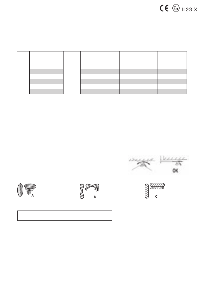
... FORMA DEL VENTAGLIO
... DESCRIZIONE
... FUNZIONAMENTO
... PROCEDURA DI SICUREZZA PER LO SCARICO DELLA PRESSIONE NEL SERBATOIO
... REGOLAZIONI*
- Raccordo entrata aria: G 1/4” M
- Pressione massima aria: 5 bar (73 psi)
- Pressione massima nel serbatoio: 1.5 bar (22 psi)
- Pressione di azionamento valvola di sicurezza: 1.8 bar (26 psi)
- Pressione d’esercizio: 2.5-3.0 bar (36-43 psi)
- Ventaglio: tutto aperto
- Aria: tutto aperto
- Prodotto: 3.5-4.5 giri
*Trattandosi di aerografo sotto pressione le
regolazioni consigliate sono del tutto indicative.
Gli aerogra della serie 9000 HD sono stati concepiti per l’applicazione di tinte per nitura in tutti quei settori dove è necessaria
una elevatissima qualità di nitura unita a una riduzione dell’emissione dei fumi.
Lo strumento non è adatto all’utilizzo con prodotti abrasivi o contenenti acidi o benzine.
Per ottenere i migliori risultati si consiglia di seguire attentamente le seguenti operazioni:
1. Utilizzare possibilmente, il tubo aria con sezione interna minima ø 8 mm (0.3”).
2. Assicurarsi che l’aria compressa utilizzata sia perfettamente ltrata da acqua, olio o altre impurità (ad esempio con l’installa-
zione di un ltro regolatore Asturomec ref. 61131 e microltro coalescente Asturomec ref. 61201, oppure della più completa ed
efciente unità ltrante e termocondizionatrice polifunzionale WALCOM TD3 PRO).
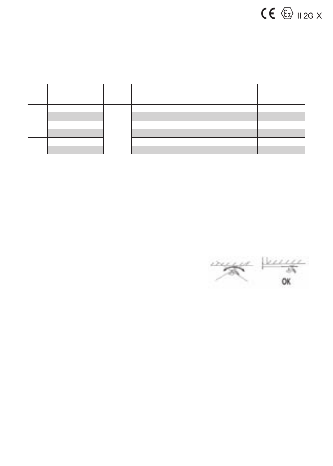
1. Impostare la distanza tra l’aerografo e la superficie da verniciare tra i 150 e i 200 mm (5.9”- 7.9”). Se l’aerografo lavora
ad una pressione troppo bassa e ad una distanza eccessiva non si otterrà l’efcienza di trasferimento ottimale.
2. Il getto dell’aerografo deve essere sempre mantenuto perpendicolare alla super-
cie da verniciare. L’applicazione della vernice deve avvenire per linee orizzontali.
Eventuali spostamenti dell’assetto durante l’emissione del prodotto verniciante
possono causare una stesura non uniforme dello strato di vernice.
3. La corretta viscosità della vernice è compresa tra 15 e 25 sec.
Coppa Ford n°4, questi valori dipendono dalle particolari applicazioni e dalla
misura di ugello utilizzata.
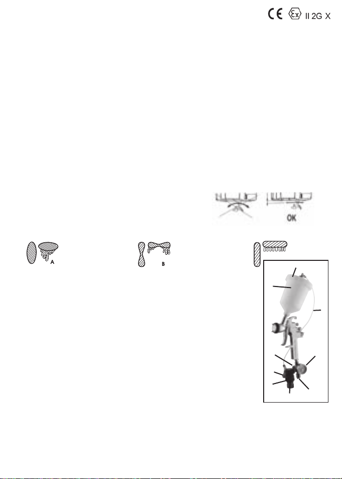
Registrare pressione aria, quantità prodotto e apertura ventaglio fino a ottenere una
impronta regolare come in fig. C
- Pressione aria troppo bassa
- Viscosità prodotto troppo alta
- Q.tà prodotto troppo alta
- Pressione aria troppo alta
- Viscosità prodotto troppo bassa
- Q.tà prodotto troppo bassa
- Getto regolare
Con riferimento alla fig.1 le parti essenziali sono:
1- entrata aria dell’aerografo;
2- regolatore di pressione dell’aria di nebulizzazione;
3- volantino per la regolazione dell’aria di nebulizzazione;
4- regolatore di pressione all’interno del serbatoio;
5 - volantino per la regolazione della pressione all’interno del serbatoio. Il regolatore è tarato, quando
è tutto aperto la pressione all’interno del serbatoio è di 1.5 bar (22 psi);
6- valvola di sicurezza per il serbatoio; entra in funzione quando la pressione all’interno del serbatoio
raggiunge 1.8 bar (26 psi);
7 - tazza per serbatoio HD;
8 - coperchio per serbatoio HD;
9 - tubo per l’aria al serbatoio HD.
ATTENZIONE! L’aerografo versione HD funziona con serbatoio in pressione.
Prima di collegare l’aerografo all’aria compressa è necessario:
- chiudere il volantino (5);
- assicurarsi che il tubo (9) sia inserito correttamente nei raccordi del regolatore (4) e del coperchio (8);
- riempire il serbatoio (7) con il prodotto da spruzzare;
- avvitare con forza il coperchio (8) sulla tazza (7);
Dopo aver collegato l’aria compressa all’entrata aria (1) procedere come segue:
A- aprire lentamente il volantino (5) per mettere in pressione il serbatoio, maggiore è la viscosità del prodotto e maggiore deve essere
la pressione all’interno del serbatoio;
B- regolare la pressione dell’aria di nebulizzazione a 2.5-3.0 bar (36-43 psi).
La seguente procedura deve sempre essere eseguita prima delle operazioni di smontaggio, pulizia dell’aerografo e rabbocco prodotto:
1 - assicurarsi di aver scollegato l’aerografo dall’impianto di alimentazione dell’aria compressa
2 - chiudere il rubinetto (5)
3 - dirigere l’ugello dell’aerografo in un contenitore metallico collegato elettricamente a terra
4 - tirare la leva per far fuoriuscire il prodotto in sovrappressione no a quando cessa il getto di vernice; a questo punto
è possibile svitare in sicurezza il coperchio (8).
1
2
3
4
5
6
7
8
9
fig.1
C
7