5
IT
PERICOLO DI INCENDIO O DI ESPLOSIONE
- L’aerografo è costruito per essere utilizzato in atmosfere esplosive classificate come zona 1 e 2 (Dir. ATEX).
Divieto di utilizzo dell’aerografo nella zona 0!
- Non utilizzare solventi e/o detergenti a base di idrocarburi alogenati (Tricloruro di Etile, Cloruro di Metilene, etc.)
perché potrebbero ossidare i pezzi galvanizzati causando reazioni chimiche anche di tipo esplosivo!
- Evitare ogni azione che può provocare incendi come fumare o generare scintille!
- Assicurarsi che l’impianto di verniciatura sia dotato di collegamento elettrico a terra!
- Utilizzare tubi per l’aria compressa antistatici per evitare accumulo di cariche elettrostatiche!
EQUIPAGGIAMENTI E PRECAUZIONI PER LA SALUTE
- Durante l’utilizzo e la pulizia dell’aerografo indossare sempre guanti ed occhiali di protezione adeguati, nonché
maschere con filtri per respirazione per uso specifico!
- Durante l’utilizzo e la pulizia dell’aerografo indossare indumenti da lavoro adeguati e antistatici per la protezione
del corpo in modo da prevenire contatti con vapori tossici, solventi o con i prodotti utilizzati!
- Indossare un’adeguata protezione per l’udito durante l’utilizzo dell’aerografo poiché potrebbe essere superato il
livello di pressione acustica di 85 dB(A)!
- Utilizzare l’aerografo in ambienti ben ventilati!
- L’utilizzo di alcuni prodotti vernicianti contenenti solventi organici può provocare intossicazione a causa dei vapori.
tossici emessi. Si raccomanda di leggere sempre le schede tecniche dei prodotti da impiegare!
- L’utilizzo di compressori o altri generatori di pressione pulsanti può produrre vibrazioni che possono comportare
lesioni da sollecitazione ripetuta specie quando il tubo che collega il compressore all’aerografo non è
sufficientemente lungo e flessibile!
AVVERTENZE PER LA SICUREZZA
-
Prima di utilizzare l’aerografo leggere attentamente le seguenti avvertenze, raccomandazioni e istruzioni per l’uso!
-
Conservare i presenti documenti assieme all’aerografo!
RISCHI DI USO IMPROPRIO
- L’aerografo deve essere utilizzato/revisionato esclusivamente da personale qualificato ed addestrato;
- Il maneggio dell’aerografo è vietato a persone la cui capacità di reagire è ridotta da droghe, alcol, farmaci o in altra
maniera;
- Mettere l’aerografo immediatamente fuori servizio/funzione nel caso di danni, scollegandolo dall’impianto di
alimentazione (entrata aria);
- Non direzionare il getto contro persone o animali!
- Non superare le pressioni massime di esercizio dichiarate!
- Non utilizzare componenti o parti di ricambio che non siano originali Walcom®!
- Lo strumento non è adatto all’utilizzo con prodotti abrasivi o contenenti acidi, soluzioni alcaline o benzine;
- Dopo ogni pulitura, dopo ogni manutenzione e/o riparazione e, comunque, prima di ogni messa in funzione
dell’aerografo, assicurarsi che le viti e i dadi siano ben stretti nella propria sede!
Mai mettere in funzione l’aerografo in presenza di danni o se mancano componenti.
- L’aerografo non deve essere mai trasformato o modificato su propria iniziativa;
- Nei modelli dotati di misuratore di pressione a sgancio/aggancio rapido, scollegare sempre il misuratore di pressione
dall’innesto aerografo/regolatore di portata durante la verniciatura.
- Per i modelli dotati di diffusore rimovibile non collegare l’aerografo all’impianto di alimentazione (entrata aria) se non
è serrato l’ugello: pericolo proiezione diffusore.
AVVERTENZE PER UNA CORRETTA PULIZIA
- Scollegare l’aerografo dall’impianto prima di effettuare qualsiasi operazione di smontaggio!
- Rimuovere la vernice residua e versarla in un altro contenitore. Smaltire correttamente l’eventuale vernice residua.
- Prima di effettuare qualsiasi operazione di pulizia, scollegare sempre dall’aerografo il misuratore e/o regolatore di
pressione.
- Smontare l’aerografo facendo attenzione ad estrarre l’ago prima di smontare l’ugello, per evitare di danneggiare la
sede di chiusura dell’ugello.
- Pulire tutti i passaggi di vernice e l’ugello. Effettuare la pulizia degli altri componenti utilizzando spazzolini
imbevuti di solvente (si consiglia il kit di pulizia Ref. 90109/W).
- Rimontare l’aerografo e spruzzare una piccola quantità di solvente per eliminare tutti i residui nel passaggio vernice.
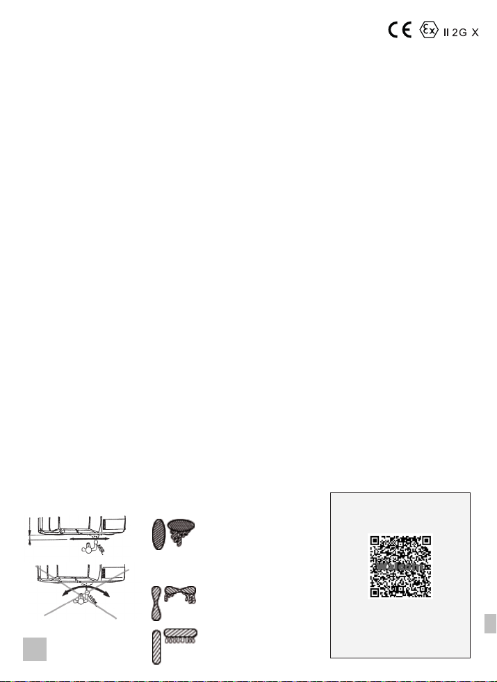
- Una pulizia incompleta potrebbe causare anomalie nel funzionamento e un degrado della forma del ventaglio.
RISCHI LEGATI ALLA PULIZIA DELL’AEROGRAFO
- L’aerografo deve essere pulito esclusivamente da personale qualificato ed addestrato;
- Prima delle operazioni di smontaggio e pulizia assicurarsi di aver scollegato l’aerografo dall’impianto di
alimentazione! Pericolo di gravi lesioni causate dalla fuga/perdita di aria compressa e/o dalla fuoriuscita della
sostanza da spruzzo!
- Per la pulitura non devono mai essere utilizzate sostanze acide o alcaline (basi, sverniciatori, etc.)!
Non usare prodotti altamente corrosivi ed abrasivi.
- Utilizzare solventi/soluzioni detergenti neutre (pH da 6 a 8);
- Non immergere l’aerografo a bagno in solvente/soluzioni detergenti. La soluzione detergente/solvente non deve mai
entrare nei canali dell’aria, altrimenti comprometterebbe la funzionalità e durata dell’aerografo;
- Non usare sistemi di pulizia ad ultrasuoni;
- Nel caso vengano usati sistemi automatici di lavaggio/pulizia, collegare sempre il tubo del dispositivo di soffiaggio
all’entrata aria dell’aerografo. In tutti gli altri sistemi di lavaggio/pulizia (manuali/semiautomatici), chiudere sempre il
volantino di regolazione entrata aria al fine di ridurre il rischio di far entrare nei canali aria il solvente/soluzioni detergenti
che potrebbero compromettere la funzionalità dell’aerografo e dei sistemi di misurazione ad essi associabili;
- Dopo la pulizia asciugare e soffiare con aria compressa pulita la pistola, l’ugello, il cappello e il serbatoio!
- Non utilizzare oggetti metallici o comunque particolari che possano danneggiare i fori dell’ugello e del cappello!
- Per i modelli dotati di diffusore rimovibile non soffiare aria compressa su passaggi interni dell’aerografo (ad esempio
dall’alimentazione aria) se non è stato precedentemente serrato l’ugello: pericolo proiezione diffusore.
CONDIZIONI PARTICOLARI PER L’UTILIZZO SICURO DELL’AEROGRAFO
Con l’utilizzo dell’aerografo i pericoli di natura termica possono derivare da:
- uso di aria compressa riscaldata;
- applicazione di prodotti di rivestimento e finitura riscaldati;
- ambiente surriscaldato.
In queste situazioni, la superficie dell’aerografo raggiunge, al massimo, la temperatura dell’aria compressa riscaldata o
del prodotto di rivestimento e finitura o dell’ambiente surriscaldato.
ATTENZIONE a quanto segue:
- la Temperatura superficiale dell’aerografo non deve superare la soglia di ustione di 43°C (UNI EN 1953 par.5.4).
Se ciò dovesse accadere allora dovranno essere utilizzate necessariamente delle protezioni per le mani (ad esempio,
guanti termoisolanti e antistatici);
- la Temperatura superficiale dell’aerografo non deve mai superare gli 85°C, temperatura sufficientemente inferiore
alla Temperatura Minima di Accensione (TMA) dei solventi comunemente utilizzati per la verniciatura in carrozzeria,
falegnameria e industria;
- in caso di dubbio chiedere al rivenditore informazioni sulla TMA del solvente prima del suo utilizzo.