Sprayit PRO 21 User manual

PRO 21
Customer Service: M-F 8am- 4pm Pacific Time - 866-409-4581
Save this Manual. Keep this manual for the safety warnings and precautions, assembly, operating, inspection, maintenance and
cleaning procedures. Write the product’s serial number in the back of the manual near the assembly diagram (or month and year of
purchase if product has no number). Keep this manual and the receipt in a safe and dry place for future reference.
RETURNS NOT ACCEPTED & WARRANTY VOID if Sprayer is not properly cleaned immediately after every use.
Clean Sprayer immediately after use to prevent permanent damage.
Read this material before using this product. Failure to do so can result in serious injury. SAVE THIS MANUAL.
Customer Service
Monday - Friday 8am - 3pm Pacific Time
Ph: 866-409-4581
RETURNS NOT ACCEPTED & WARRANTY VOID
If Sprayer is not properly cleaned immediately after every use.Clean Sprayer immediately to
prevent permanent damage.
PROFESSIONAL
ELECTRIC AIRLESS
PAINT SPRAYER

Table of Contents
.........................................................................................................................................................................
Safety
Specifications
Setup
Operation
Maintenance
Parts List and Diagram
5
7
9
11
15
19
.........................................................................................................................................................
..........................................................................................................................................................................
................................................................................................................................................................
.........................................................................................................................................................
......................................................................................................................................
WARNING SYMBOLS AND DEFINITIONS
IMPORTANT SAFETY INSTRUCTIONS
1. SAVE THESE INSTRUCTIONS – To reduce the risks of fire or explosion, electrical shock, and the injury to persons. Read and
understand all instructions included in this manual. Be familiar with the controls and the proper usage of the equipment.
2. WARNING – To reduce the risk of fire or explosion:
a. Do not spray fiammable or combustible materials near an open fiame or sources of ignition such as cigarettes, motors,
and electrical equipment.
b. For units intended for use with only water-based or mineral spirit-type materials with a minimum fiash point of
38°C (100°F) – Do not spray or clean with liquids having a fiash point less than 38°C (100°F).
c. Paint or solvent fiowing through the equipment is able to result in static electricity. Static electricity creates a risk of
fire or explosion in the presence of paint or solvent fumes. All parts of the spray system, including the pump, hose
assembly, spray gun, andobjects in and around the spray area shall be properly grounded to protect against static
discharge and sparks. Use only conductive or grounded high-pressure airless paint sprayer hoses specified by the
manufacturer.
d. Verify that all containers and collection systems are grounded to prevent static discharge.
e. Connect to a grounded outlet and use grounded extension cords. Do not use a 3 to 2 adapter.
f. Do not use a paint or a solvent containing halogenated hydrocarbons. See operating instructions for examples of
these types of materials.
g. Keep spray area well ventilated. Keep a good supply of fresh air moving through the area. Keep pump assembly in a
well ventilated area. Do not spray pump assembly.
h. Do not smoke in the spray area.
i. Do not operate light switches, engines, or similar spark producing products in the spray area.
j. Keep area clean and free of paint or solvent containers, rags, and other fiammable materials.
Page 2 Page 3
k. Know the contents of the paints and solvents being sprayed. Read all Material Safety Data Sheets (MSDS) and container
labels provided with the paints and solvents. Follow the paint and solvent manufacturer’s safety instructions.
l. Fire extinguisher equipment shall be present and working.
3. WARNING – To reduce the risk of skin injection:
a. Do not aim the gun at, or spray any person or animal.
b. Keep hands and other body parts away from the discharge. For example, do not try to stop leaks with any part of the
body.
c. Always use the nozzle tip guard. Do not spray without nozzle tip guard in place.
d. Only use a nozzle tip specified by the manufacturer.
e. Use caution when cleaning and changing nozzle tips. In the case where the nozzle tip clogs while spraying, follow the
manufacturer’s instructions for turning off the unit and relieving the pressure before removing the nozzle tip to clean.
f.
g.
Do not leave the unit energized or under pressure while unattended. When the unit is not in use, turn off the unit and
relieve the pressure in accordance with the manufacturer’s instructions.
High-pressure spray is able to inject toxins into the body and cause serious bodily injury. In the event that injection
occurs, seek medical attention immediately.
h. Check hoses and parts for signs of damage. Replace any damaged hoses or parts.
i.This system is capable of producing 3000 psi. Only use replacement parts or accessories that are specified by the
manufacturer and that are rated a minimum of 3000 psi.
j. Always engage the trigger lock when not spraying. Verify the trigger lock is functioning properly.
k. Verify that all connections are secure before operating the unit.
l. Know how to stop the unit and bleed pressure quickly. Be thoroughly familiar with the controls.
4. WARNING – To reduce the risk of injury:
a. Always wear appropriate gloves, eye protection, and a respirator or mask when painting.
b. Do not operate or spray near children. Keep children away from equipment at all times.
c. Do not overreach or stand on an unstable support. Keep effective footing and balance at all times.
d. Stay alert and watch what you are doing.
e. Do not operate the unit when fatigued or under the infiuence of drugs or alcohol.
f. Do not kink or over-bend the hose.
g. Do not expose the hose to temperatures or to pressures in excess of those specified by the manufacturer.
h. Do not use the hose as a strength
member to pull or lift the equipment.
IMPORTANT SAFETY INSTRUCTIONS
1. Keep the work area clean and well lighted.
Cluttered benches and dark areas increase the risks of electric shock, fire, and injury to persons.
2. Operate only in a well-ventilated area.
Paint thinners and solvents may be harmful if inhaled.
3. Do not operate the sprayer in explosive atmospheres, such as in the presence of flammable liquids, gases, or dust.
The sprayer is able to create sparks resulting in the ignition of the dust or fumes.
4. Keep bystanders, children, and visitors away while operating the tool.
Distractions are able to result in the loss of control of the tool.
Electrical Safety
1. Sprayer plugs must match the outlet. Never modify the plug in any way.
Do not use any adapter plugs with grounded sprayers.Unmodified plugs and matching outlets will reduce risk of electric shock.
2. Avoid body contact with grounded surfaces such as pipes, radiators, ranges and refrigerators.
There is an increased risk of electric shock if your body is grounded.
3. Do not expose sprayers to rain or wet conditions.
Water entering a sprayer will increase the risk of electric shock.
4. Do not abuse the cord. Never use the cord for carrying, pulling or unplugging the sprayer.
Keep cord away from heat, oil, sharp edges or moving parts. Damaged or entangled cords increase the risk of electric shock.
5. When operating a sprayer outdoors, use an extension cord suitable for outdoor use.
Use of a cord suitable for outdoor use reduces the risk of electric shock.
6. If operating a sprayer in a damp location is unavoidable, use a Ground Fault Circuit Interrupter (GFCI) protected
supply.
Use of a GFCI reduces the risk of electric shock.
PRO 21
PRO 21
Page 4 Page 5
IMPORTANT SAFETY INSTRUCTIONS
1. Keep the work area clean and well lighted.
Cluttered benches and dark areas increase the risks of electric shock, fire, and injury to persons.
2. Operate only in a well-ventilated area. Paint thinners and solvents may be harmful if inhaled.
3. Do not operate the sprayer in explosive atmospheres, such as in the presence of flammable liquids, gases,
or dust.
The sprayer is able to create sparks resulting in the ignition of the dust or fumes.
4. Keep bystanders, children, and visitors away while operating the tool.
Distractions are able to result in the loss of control of the tool.
PERSONAL SAFETY
1. Stay alert. Watch what you are doing and use common sense when operating the tool.
Do not use the tool while tired or under the influence of drugs, alcohol, or medication. A moment of inattention while
operating the tool increases the risk of injury to persons.
2. Dress properly. Do not wear loose clothing or jewelry.
Contain long hair. Keep hair, clothing, and gloves away from moving parts.
Loose clothes, jewelry, or long hair increases the risk of injury to persons as a result of being
caught in moving parts.
3. Avoid unintentional starting. Be sure the trigger is off before connecting to the power supply.
Do not carry the sprayer with your finger on the trigger or connect the sprayer to the power supply with
the trigger on.
4. Do not overreach. Keep proper footing and balance at all times.
Proper footing and balance enables better control of the tool in unexpected situations.
5. Use safety equipment.
Wear protective paint spraying gloves and a MSHA/NIOSH-approved respirator during use.
Non-skid safety shoes and a hard hat must be used for the applicable conditions.
6. Always wear eye protection.Wear ANSI-approved safety goggles.
TOOL USE AND CARE
1. Do not force the tool. Use the correct tool for the application.
The correct tool will do the job better and safer at the rate for which it was designed.
2. Do not use the sprayer if the switch does not turn it on and off.
Any sprayer that cannot be controlled with the switch is dangerous and must be repaired.
3. Disconnect the tool from the power source before any adjustments, changing accessories, or storing the tool.
Such preventive safety measures reduce the risk of starting the tool unintentionally.
4. Store the tool when it is idle out of reach of children and other untrained persons.
A tool is dangerous in the hands of untrained users.
5. Check for misalignment or binding of moving parts, breakage of parts, and any other condition that affects the
tool’s operation.
If damaged, have the tool serviced before using. Many accidents are caused by poorly maintained tools. There is a risk of
bursting if the tool is damaged.
6. Use only accessories that are identified by the manufacturer for the specific tool model.
Use of an accessory not intended for use with the specific tool model, increases the risk of injury to persons.
SERVICE
1. Tool service must be performed only by qualified repair personnel.
2. When servicing a tool, use only identical replacement parts. Use only authorized parts.
3. Use only lubricants supplied with the tool or specified by the manufacturer.
4. Customer Service: M-F 8am - 3pm Pacific Time 866-409-4581
IMPORTANT SAFETY INSTRUCTIONS
1. INJECTION HAZARD!
Although this paint gun is airless, it still puts out paint at a very high pressure.
Through improper use, paint can be injected through a person’s skin, leading to serious injury,
possibly amputation. If paint is accidentally injected into someone’s skin, contact a doctor immediately.
Do not treat an injection injury as a simple cut. Injection can lead to amputation and requires immediate
surgical treatment.
2. Do not direct spray at people or animals.
Do not place your hand in front of Spray Gun’s nozzle or attempt to deflect paint spray with your hand during use.
Gloves and clothing don’t offer adequate protection from toxic paints, sealers, or stains.
3. Do not spray flammable materials in vicinity of open flame or near ignition sources.
Motors, electrical equipment, andcontrols can cause electrical arcs that will ignite a flammable gas or vapor.
Do not store flammable liquids or gases in vicinity of this unit.
4. Do not come into contact with a fluid stream created by a leak in the paint hose.
5. Do not leave Paint Sprayer pressurized while unattended.
6. Do not clean Spray Gun tip while it is still connected to paint hose.
7. Keep the trigger and the electrical cord plug clean and paint-free.
8. Do not run Paint Sprayer while empty. Damage to the unit may occur.
9. Do not use Paint Sprayer to spray asbestos, metallic paints, glazes, red lead, cement, ground chalk, abrasive grainy
paints containing lime, or bleach.
These will damage the spray gun and void the warranty.
10. Read all of the information concerning coating products and cleaning solvents.
Do NOT use bleach, low-flash naphthalene, acetone, alcohol or toluene when cleaning Paint Sprayer equipment.
11. Do not use bleach or halogenated hydrocarbon solvents (DCM, 1,1,1–trichloroethane, methyl bromine, carbon
tetrachloride, and ethyl iodide).
Long term exposure to many chlorinated hydrocarbons through inhalation can result in liver and kidney toxicity. Exposure of
unprotected skin to the solvents used can cause defatting of the skin resulting in dermatitis. Methylene chloride and vinyl
chloride have also been shown to be human carcinogens. Some of these solvents are flammable. Welding operations near
the these materials can create phosgene, a highly toxic gas.
12. Many spray guns contain aluminum, which reacts strongly to chlorinated solvents. Contact the solvent or coating
manufacturer as needed regarding potential chemical reactions.
13. Industrial applications must follow OSHA requirements.
14.
15.
Spraying hazardous materials may result in serious injury or death.
Do not spray pesticide, acid, corrosive material, fertilizer, or toxic chemicals.
Paints and solvents may be harmful or fatal if swallowed or inhaled.
Avoid prolonged skin contact with solvents or paints as they will irritate skin. After any contact, immediately wash off exposed
area with hot, soapy water.
16. Keep paint hose away from sharp objects.
Bursting hoses may cause injury. Examine hoses regularly and replace if damaged.
17. When flushing Paint Sprayer system, use lowest possible pressure setting.
18. All hoses and spray gun accessories used with Paint Sprayer must be pressure rated at or above 3000 PSI.
19. The Paint Sprayer must be plugged into an outlet that is grounded in accordance with all local codes and
ordinances.
20. Use caution while spraying on windy days.
21. Do not use Paint Sprayer without the Spray Gun’s nozzle guard in place.
22. Paint Sprayer’s housing may become hot during use.
Do not touch housing until it has completely cooled.
23. Remove Spray Tip or turn to cleaning position BEFORE cleaning or flushing Paint Sprayer system.
24. Do not use pliers to tighten or loosen high pressure connections.
25. Sparks from improper grounding can ignite fumes!
Follow all local regulations regarding the use
of fluid supply containers and solvent pails used with flushing the Paint Sprayer. Use only conductive
metal pails placed on a grounded (concrete) surface. Do not place pails on nonconductive surfaces
(such as cardboard or paper). Ground all metal pails by clamping one end of a ground wire to the pail
and the other end to a grounded structure (such as a nearby pipe).
Maintain grounding, even when flushing or relieving pressure from Paint Sprayer into metal pail. The force of the spray can
knock a metal pail over, so hold down the metal pail and keep the metal part of the spray gun set against the grounded
metal pail when pressing the spray gun trigger.
26. People with pacemakers should consult their physician(s) before use.
Electromagnetic fields in close proximity to heart pacemaker could cause pacemaker interference or pacemaker failure.
Page 6 Page 7
GROUNDING
TO PREVENT ELECTRIC SHOCK AND DEATH FROM INCORRECT GROUNDING WIRE CONNECTION:
Check with a qualified electrician if you are in doubt as to whether the outlet is properly grounded.
Do not modify the power cord plug provided with the tool.
Never remove the grounding prong from the plug. Do not use the tool if the power cord or plug is
damaged. If damaged, have it repaired by a service facility before use. If the plug will not fit the outlet, have a
proper outlet installed by a qualified electrician.
SAVE THESE INSTRUCTIONS.
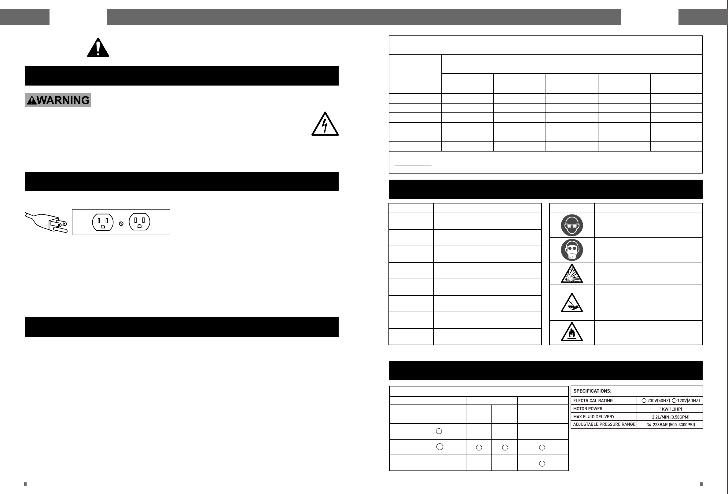
3-Prong Plug and Outlet
Grounded Tools: Tools with Three Prong Plugs
1. Sprayers marked with “Grounding Required” plug. The plug must be connected to a properly malfunction or break
down, grounding provides a low resistance path to carry electricity away from the user, reducing the risk of electric
shock. (See 3-Prong Plug and Outlet.)
2. The grounding prong in the plug is connected through the green wire inside the cord to the grounding system in the
sprayer. The green wire in the cord must be the only wire connected to the sprayer’s grounding system and must never
be attached to an electrically “live” terminal. (See 3-Prong Plug and Outlet.)
3. The sprayer must be plugged into an appropriate outlet, properly installed and grounded in accordance with all codes
and ordinances. The plug and outlet should look like those in the preceding illustration. (See 3-Prong Plug and Outlet.)
Extension Cords
1.
2.
3.
4.
Grounded sprayers require a three wire extension cord. Double Insulated sprayers can use either a two or three wire
extension cord.
As the distance from the supply outlet increases, you must use a heavier gauge extension cord. Using extension cords
with inadequately sized wire causes a serious drop in voltage, resulting in loss of power and possible sprayer damage.
(See Table A.)
The smaller the gauge number of the wire, the greater the capacity of the cord. For example, a14 gauge cord can carry
a higher current than a 16 gauge cord. (See Table A.)
When using more than one extension cord to make up the total length, make sure each cord contains at least the
minimum wire size required. (See Table A.)
5. If you are using one extension cord for more than one sprayer, add the nameplate amperes and use the sum to
determine the required minimum cord size. (See Table A.)
6. If you are using an extension cord outdoors, make sure it is marked with the suff ix “W-A” (“W” in Canada) to indicate it
is acceptable for outdoor use.
7. Make sure the extension cord is properly wired and in good electrical condition. Always replace a damaged extension
cord or have it repaired by a qualified electrician before using it.
8. Protect the extension cords from sharp objects, excessive heat, and damp or wet areas.
0 – 2.0
2.1 – 3.4
3.5 – 5.0
5.1 – 7.0
7.1 – 12.0
12.1 – 16.0
16.1 – 20.0
18
18
18
18
18
14
12
18
18
18
16
14
12
10
18
18
16
14
12
10
-
18
16
14
12
10
-
-
18
16
14
12
10
-
-
25’ 50’ 75’ 100’ 150’
RECOMMENDED MINIMUM WIRE GAUGE FOR EXTENSION CORDS* (120/240 VOLT)
NAMEPLATE
AMPERES
(at full load)
EXTENSION CORD LENGTH
*Based on limiting the line volt age drop to five volts at 150% of
the rated amperes.
TABLE A
Symbols
V
~
A
PSI
CFM
SCFM
NPT
NPS
Symbol Property or Statement
Volts
Alternating Current
Amperes
Pounds per square inch of pressure
Cubic Feet per Minute flow
Cubic Feet per Minute flow at
standard conditions
National pipe thread, tapered
National pipe thread, straight
Symbol Property or Statement
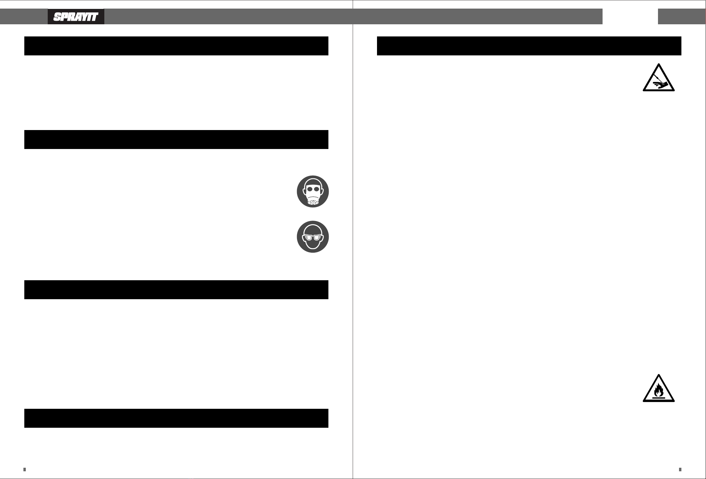
WARNING marking concerning
Risk of Eye Injury.
Wear ANSI-approved eye protection.
WARNING marking concerning
Risk of Respiratory Injury.
Wear NIOSH-approved respirator.
WARNING marking concerning
Risk of Explosion.
WARNING marking concerning Risk of
Injection Injury.Do not direct spray at
hands or body. Have injection injury
treated immediately
WARNING marking concerning Risk of
Fire.Do not use solvents improperly.
Specifications
Light
Stains &
Laquer
Medium
TIP CHART
Tip
Size
311
515
619
Heavy
Primer
Interior
Paint
Exterior
Paint
Electrical Power Requirements
110 - 120 Volts 60 Hertz 15 amp outlet,required.
Ensure that the power supply is operating normally.
PRO 21

Page 8 Page 9
Setup – Before Use
Read the ENTIRE IMPORTANT SAFETY INFORMATION section at the beginning of this manual including
all text under subheadings therein before set up or use of this product.
Note:For additional information regarding the parts listed in the following pages, refer to the Assembly Diagram near
the end of this manual.
Components and Controls
Power
Switch
Pressure
Knob
Spray
Hose
Outlet
Power
Cord
Prime/Spray
Valve
Priming
Hose
Suction
Hose
Assembly
1. Attach Spray Hose
Attach Spray Hose to Spray Hose Outlet. Tighten securely with two wrenches.
2. Install Filter in Spray Gun
a. For water-based paints, use pre-installed 60 mesh coarse filter.
b. For oil-based paints, remove coarse filter andinstall 100 mesh fine filter.
c. Use proper Spray Tip according to Tip Chart on page . .Remove Handle from Spray Gun with included wrench.Remove filter by
turning it counter clockwise.Replace filter and reassemble Spray Gun.
3. Attach Spray Gun
Attach Spray Gun to Spray Hose. Tighten securely with two included wrenches.
Spray
Hose
Outlet
Filter
Handle
Secure
wrench on
flat spots
Operating Instructions
Read the ENTIRE IMPORTANT SAFETY INFORMATION section at the beginning of this manual including all text
under subheadings therein before set up or use of this product.
INJECTION HAZARD!
Although this paint gun is airless, it still puts out paint at a very high pressure. Through improper use, paint
can be injected through a person’s skin, leading to serious injury, possibly amputation.
If paint is accidentally injected into someone’s skin, contact a doctor immediately.
Do not treat an injection injury as a simple cut. Injection can lead to amputation and requires
immediate surgical treatment. Inspect tool before use, looking for damaged, loose, and missing parts. If any
problems are found, do not use tool until repaired.
Lock/Unlock Trigger
WARNING! TO PREVENT SERIOUS INJURY: Risk of Injection - Set Trigger Lock when Spray Gun not in use.
1. Rotate Trigger Lock all the way back to lock Trigger.
2. Rotate Trigger Lock forward to unlock Trigger.
Trigger
Lock
Lock Unlock
PRO 21
Handle
Page 10 Page 11
Depressurize Sprayer
WARNING! TO PREVENT SERIOUS INJURY: Risk of Injection - Unit maintains pressure after
shut-down - Before servicing, cleaning, or removing any part, shut off power and relieve pressure.
Refer to this section when instructed to depressurize sprayer.
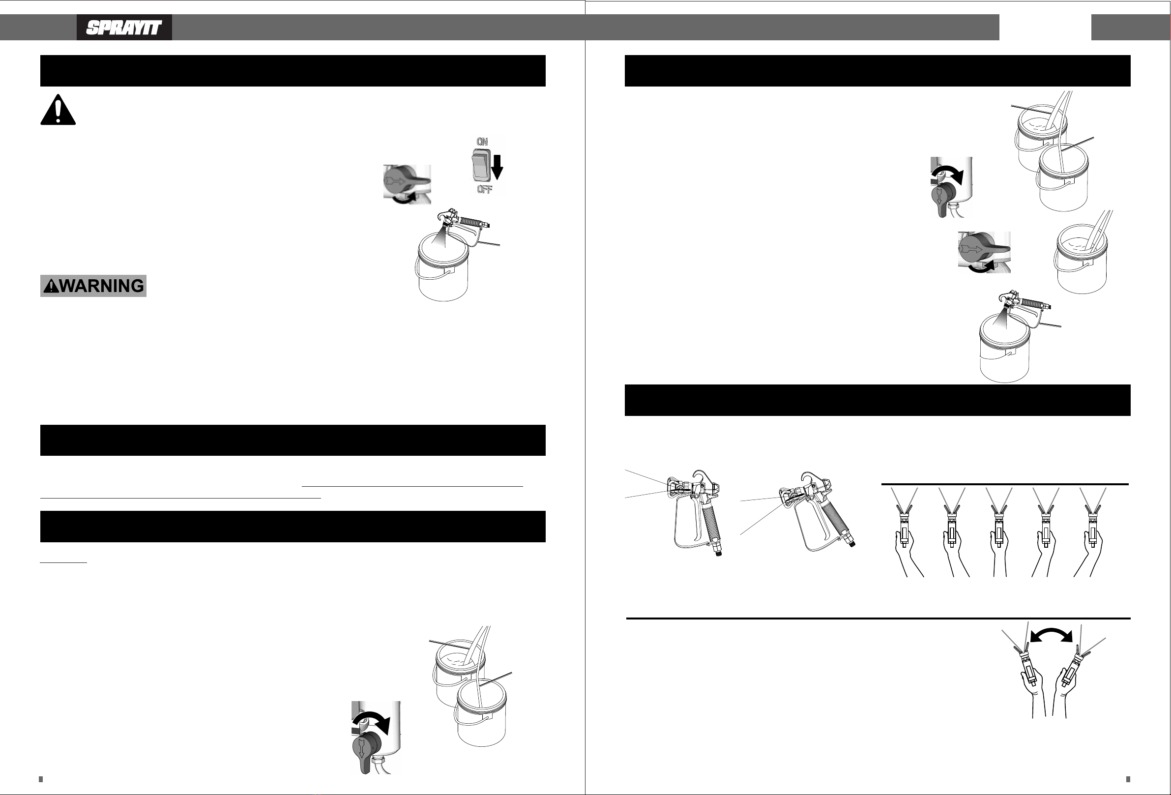
1. Turn Power Switch off.
2. Lock Trigger.
3. Turn Pressure Knob to lowest setting.
4. Reverse Spray Tip.
5. Rotate PRIME/SPRAYValve to SPRAY position.
6. Unlock Trigger.
7. Point Spray Gun at interior side of empty grounded metal container. Hold
Trigger Guard against container to ground Spray Gun.
8. Press Trigger until pressure is relieved, then release and lock Trigger.
9. Rotate Spray Tip to SPRAYposition.
10. Rotate PRIME/SPRAYValve to PRIME position when Sprayer not in use.
Trigger
Guard
Empty
TO PREVENT SERIOUS INJURY:
Do not spray Flammable or combustible liquids in a conned area. Spray area must be well ventilated. Do not smoke while
spraying or spray where sparks or fiame is present. Keep pump assembly in a well ventilated area at least 20 feet (6.1 m) from the
spray area. Do not spray the pump assembly. Do not use bleach or halogenated hydrocarbon solvents (DCM, 1,1,1–
fitrichloroethane, methyl bromine, carbon tetrachloride, and ethyl iodide). Long term exposure to many chlorinated hydrocarbons
through inhalation can result in liver and kidney toxicity. Exposure of unprotected skin to the solvents used can cause defatting of
the skin resulting in dermatitis. Methylene chloride and vinyl chloride have also been shown to be human carcinogens. Some of
these solvents are flammable. Welding operations near the these materials can create phosgene, a highly toxic gas. Wear ANSI-
approved safety goggles, MSHA/NIOSH-approved respirator, and heavy-duty work gloves during use.
Priming
WARNING! TO PREVENT SERIOUS INJURY: Only water-based materials or materials with a minimum ?ash point
of 38°C (100°F) should be used for spraying and cleaning. Only use water or mineral spirits for priming and
cleaning.Only use water-based or oil-based paint for spraying.
Prime with Solvent
WARNING! To prevent high pressure solvent or paint splatter, remove Nozzle Guard and Spray Tip according to Spray Tip and
Nozzle Guard on page 20.
1. Depressurize Sprayer according to Depressurize Sprayer on page 11.
2. Lock Gun Trigger Lock.
3. Cover floor under Sprayer and containers with drop cloth.
4. Apply pump lubricant according to Lubricate Pump on page 19.
5. Designate two 1 gallon or larger containers, one for solvent and one for
waste. If using mineral spirits, use metal containers.
6. Separate Priming Hose from Suction Hose.
a. Place Suction Hose on bottom of solvent container.
b. Place Priming Hose on bottom of waste container.
7. Fill solvent container with enough solvent to cover Suction Filter by 1".Water for
water-based paint.? Mineral spirits for oil-based paint.
8. Prime Pump:
a. Turn Pressure Knob to PRIME/CLEAN indicator.
b. Rotate PRIME/SPRAY Valve to PRIME position
9. Prime with paint according to Prime with Paint on page 13.
Priming
Hose
Suction
Hose
Solvent
Waste
Prime to Spray
1. Prime with solvent according to Prime with Solvent on page 12.
2. Lock Trigger.
3. CAUTION! To prevent high pressure solvent or paint splatter, remove Nozzle
Guard and Spray Tip according to Spray Tip and Nozzle Guard on page 20.
4. Strain paint through paint strainer.
5. Remove Suction Hose from solvent container and place on bottom paint container.
6. Leave Priming Hose in waste container.
7. Prime Pump:
a. Turn Pressure Knob to PRIME/CLEAN indicator.
b. Rotate PRIME/SPRAY Valve to PRIME position.
c. Turn Power Switch on. Pump will start.
If pump does not start, turn Pressure Knob clockwise until it starts.
d. When solvent has been purged and paint begins to flow out of Priming Hose,
rotate PRIME/SPRAY Valve to SPRAY position. Pump will cycle on then stop.
8. Prime Spray Gun:
a. Unlock Trigger.
b. Point Spray Gun at interior side of waste container.
c. Press Trigger.
d. When solvent has been purged and paint begins to flow, release and lock Trigger.
Pump will cycle on then stop.
Rotate PRIME/SPRAY Valve to PRIME position.
Remove Priming Hose from solvent container and place into paint container.
Spray paint according to Spraying on page 15. NOTE:Dispose of solvent,
paint and waste according to local hazardous waste standards.
Priming
Hose
Suction
Hose
Solvent
Waste
Paint
Spraying
WARNING! TO PREVENT SERIOUS INJURY: Only water-based materials or materials with a minimum fiash point of 38°C (100°F)
should be used for spraying and cleaning. Only use water or mineral spirits for priming and cleaning. Only use water-based or
oil-based paint for spraying.
Proper Spraying Techniques Keep the Spray Gun
upright and at a right angle to the workpiece.
Correct Incorrect
Correct Gun Angle Move your arm, not just your wrist.
Point gun directly towards the surface and maintain an
even, steady distance and speed.
Before use, the Sprayer must be primed according to Priming on page 12.
Note:Remove or cover objects that you want to protect from overspray and paint mist.
1. Attach Nozzle Guard and Spray Tip according to Spray Tip and Nozzle Guard on page 20.
2. Rotate PRIME/SPRAY Valve to SPRAY position.
3. Turn Pressure Knob to HIGH SPRAY indicator.
Note:Practice painting techniques on a scrap workpiece.
4. Point Spray Gun 10" - 12" away from scrap workpiece.
5. Unlock and press Trigger fully, spraying, following “Proper Spraying Techniques”
and “To Avoid Paint Build Up”.
6. Adjust Pressure Knob as necessary to achieve desired consistency and reduce overspray.
Note:The motor has thermal overload protection. If unit overheats, allow approximately 45 minutes for unit to cool.
Empty
Trigger
Guard
PRO 21
Move hand before triggering the spray gun and stop
trigging before stopping movement. This will reduce runs.

Page 12 Page 13
7. When finished spraying:
a. Rotate PRIME/SPRAY Valve to PRIME position.
b. Turn Power Switch off.
c. Clean according to User?Maintenance Instructions on page
a. Lock Trigger
b. Reverse Spray Tip.
c. Unlock Trigger and Spray on scrap workpiece.
d. Release and lock Trigger.
Note: If Spray Tip won’t clear, replace according to Spray Tip and Nozzle Guard on page 20.
NOTE:Dispose of solvent, paint and waste according to local hazardous waste standards.
User-Maintenance Instructions
After Every Use - Cleaning
WARNING! TO PREVENT SERIOUS INJURY: Only water-based materials or materials with a minimum fiash point of 38°C (100°F)
should be used for spraying and cleaning.
Only use water or mineral spirits for priming and cleaning. Only use water-based or oil-based paint for spraying.
Bucket Method
1. Turn Power Switch off.
2. Depressurize Sprayer according to Depressurize Sprayer on page 10.
3. Lock Trigger.
4. CAUTION! To prevent high pressure solvent or paint splatter, remove Nozzle Guard,
5. Spray Tip, and Seal according to Spray Tip and Nozzle Guard on page 20.
CAUTION! TO PREVENT INJURY:
TO PREVENT FIRE: When using mineral spirits, use metal containers only.
DO NOT use plastic containers.
12. Clean Hoses and Spray Gun
5. Designate two 1 gallon containers, one for solvent and one for waste.
6. Remove Suction and Priming Hoses from paint container and wipe off excess paint.
7. Place Suction Hose on bottom of solvent container.
8. Place Priming Hose on bottom of waste container.
9. Fill solvent container with enough solvent to cover filter by 4". Water for water-based paint.?
Mineral spirits for oil-based paint.
10. Place Nozzle Guard, Spray Tip and Seal in small container of:
Soap and water for water-based paint. Mineral spirits for oil-based paint.
11. Clean Pump
b. Unlock Trigger.
c. Point Spray gun into paint container, then press Trigger to pump excess paint back into paint container.
d. Point Spray Gun at interior side of waste container.
e. Press Trigger until solvent runs clear . then release the locked trigger
Note: If using mineral spirits, hold Trigger Guard against edge of metal waste container to ground Spray Gun.
Empty
Trigger
Guard
Priming
Hose
Suction
Hose
Solvent
Waste
Spray
Hose
Outlet
Filter
Tube
Filter
Inlet
Filter
Housing
Filter
Handle
8. Clearing Spray Tip Blockage
a. Unlock Trigger.
b. Point Spray gun into paint container, then press Trigger to pump excess paint back into paint
container.
c. Point Spray Gun at interior side of waste container.
d. Press Trigger until solvent runs clear, then release and lock Trigger.
e. Turn off water.
13. When finished:
14. Rotate PRIME/SPRAY Valve to PRIME position
15. Rotate PRIME/SPRAY Valve to PRIME position.
a. Add Suction Hose and Prime Hose to a container with Pump Protector.
b. Prime with Pump Protector.
c. Turn off sprayer and unplug sprayer.
16. Clean Accessories.
a. Depressurize Sprayer according a page 11.
b. Turn Power Switch Off
c. Unplug Sprayer
d. Remove Spray Gun from Spray Hose
e. Remove Handle from Spray Gun with two wrenches.
f. Remove Filter by turning it counterclockwise
g. Place Filter in container of solvent with other accessories.
h. Remove Manifold Filter and place Filter in container of solvent.
i. Use a brush to clean filters
j. Let Filters Dry
k. Reassemble
l. Remove Suction and Prime Hoses from Sprayer
m. Add Pump Protector to the lower piston to reduce corrosion and freezing.
17. Store Sprayer in a clean dry location out of reach of children.
If Sprayer will not be used for longer than 48 hours, store according to Long Term Storage on page 18.
Add Pump Protector to the lower piston to reduce corrosion and freezing.
NOTE: Dispose of solvent, paint and waste according to local hazardous waste standards.
PRO 21
Pump
Protector
Page 14 Page 15
Long-Term Storage
1. Clean Sprayer according to User and Maintenance Instructions.
2. Depressurize Sprayer according to Depressurize Sprayer on page 10.
3. Designate storage area in a clean dry location out of reach of children.
4. Open included Pump Protector bottle.
5. Place Suction and Prime Hoses in bottle.
6. Rotate PRIME/SPRAY Valve to PRIME position.
7. Plug Sprayer into 120VAC grounded GFCI outlet.
8. Turn Power Switch on. Pump will start. If pump does not start, turn Pressure Knob clockwise until it starts.
9. When Pump Protector begins to flow out of Priming Hose, turn Power Switch off.
10. Unplug Sprayer.
11. Remove Suction and Prime Hose. Put sprayer on it's back. Add Pump Protector to lower section of pump.
12. Leave sprayer on it's back and Pump Protector in lower pump. Pump Protector protects from rusting and freezing.
Maintenance and Lubrication
1. BEFORE EACH USE, inspect the general condition of the tool.
Check for: loose hardware, misalignment or binding of moving parts, damaged cord/electrical wiring,damaged Nozzle Guard
or Spray Tip,damaged Spray Hose,cracked or broken parts, and any other condition that may affect its safe operation.
2. AFTER USE, wipe external surfaces of the tool with clean cloth.
3. Do not attempt to repair hose. Hose must be replaced if damaged.
4. Store in clean dry location out of reach of children.
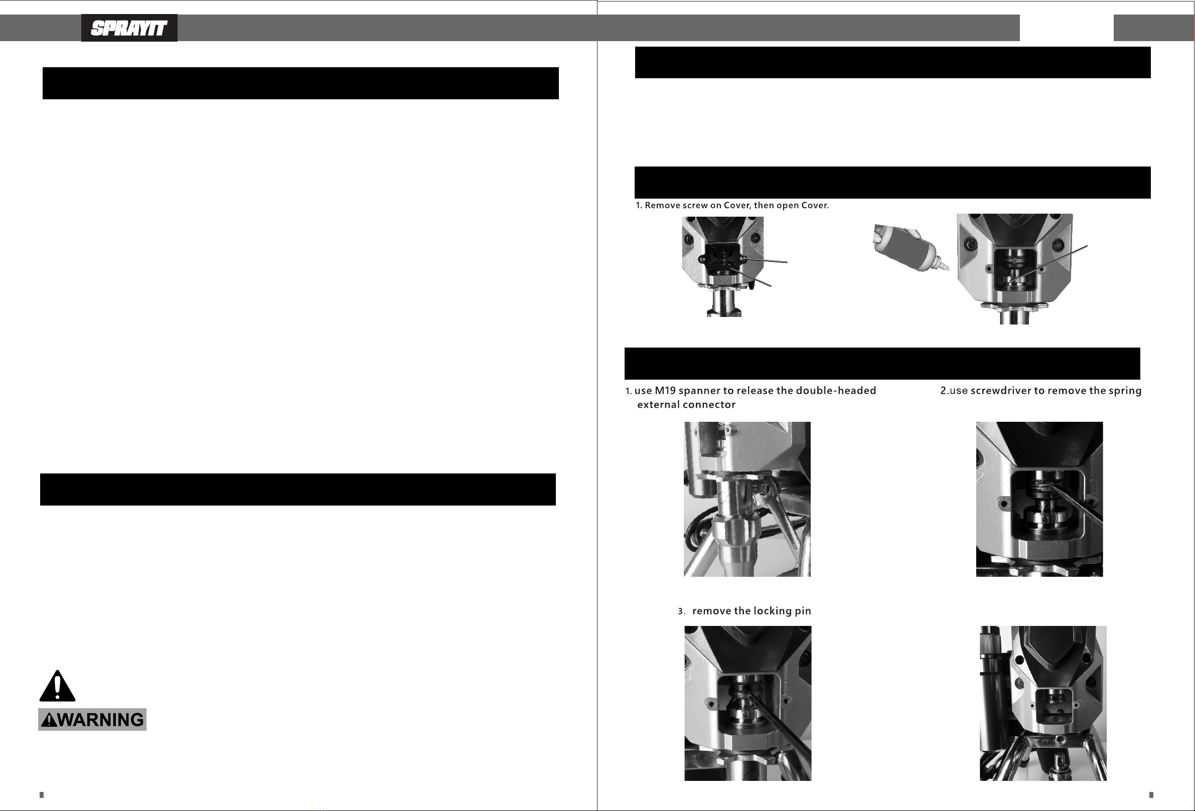
Maintenance and Add Packing Saver
Replace Pump
4. remove the flower locking nut and pump
Screw
Apply
Packing Saver
here
Cover
Cleaning For Water-Based Paint Only
1. Turn Power Switch off.
2. Depressurize Sprayer according to Depressurize Sprayer on page 10..
3. Lock Trigger.
4. CAUTION! To prevent high pressure solvent or paint splatter, remove Nozzle Guard, Spray Tip, and Seal according to Spray
Tip and Nozzle Guard on page 16.
5. Designate one 1 gallon container for waste.
6. Remove Suction and Priming Hoses from paint container and wipe off excess paint.
7. Place Suction and Priming Hoses on bottom of waste container.
8. Place Nozzle Guard, Spray Tip and Seal in small container of soap and water.
9. Remove Inlet Screen and Gasket from Suction Tube and place in small container of soap and water.
10. Clean Pump
a. Turn Pressure Knob to PRIME/CLEAN indicator.
b. Rotate PRIME/SPRAY Valve to PRIME position.
c. When paint has been purged and water begins to run clear, rotate PRIME/SPRAY Valve to SPRAY position.
11. Clean Hoses and Spray Gun
a. Unlock Trigger.
b. Point Spray gun into paint container, then press Trigger to pump excess paint back into paint container.
c. Point Spray Gun at interior side of waste container.
d. Press Trigger until solvent runs clear, then release and lock Trigger.
e. Turn off water.
12. When finished:
13. Rotate PRIME/SPRAY Valve to PRIME position.
a. Turn off Power Switch
b. Unplug Sprayer
c. Remove Hoses from containers.
d. Let Hoses dry completely before storage.
14. Clean Accessories on page 12 to finish cleaning and storing procedures.
TO PREVENT SERIOUS INJURY FROM ACCIDENTAL OPERATION:Unplug the Sprayer from its electrical outlet
before performing any inspection or maintenance procedures.TO PREVENT SERIOUS INJURY FROM TOOL
FAILURE: Do not use damaged equipment. If abnormal noise, vibration, or leaking air occurs, have the problem
corrected before further use.
Procedures not specifically explained in this manual must be performed only by a qualified technician.
PRO 21

Page 16 Page 17
Spray Tip and Nozzle Guard
1. Seat Seal on end of Spray Tip, then insert Seal into back
of Nozzle Guard.
SPRAY
3. Insert Spray Tip into guard. Push and rotate tip clockwise.
Lock tip into place.
2. Thread Nozzle Guard onto Spray Gun.
Turn nut by hand until almost tight, then holding nut and
Nozzle Guard together, tighten completely.
Do not overtighten.
4. Install Tip into Nozzle Guard, then rotate until
SPRAY end is facing forward.
Troubleshooting
Remove
1. During operation:Remove Spray Tip from Nozzle Guard, then remove Nozzle Guard from Spray Gun.
2. During cleaning or changing tip size:Remove Spray Tip from Nozzle Guard, then remove Nozzle Guard from Spray Gun.
Insert Spray Tip into front of Nozzle Guard to remove Seal.
SPRAY
Nozzle
Guard
Seal
Spray
Tip
5. Clear Clog by reversing the spray tip
PRO 21

Page 18 Page 19
Parts List and Diagram
12.7 steel balls
Suction Valve seat
Seat ring
Lower Block
Double-headed external tooth connector NPS R
Pump Body Seal Ring Lock Nut
PLUNGER SEAL SUPPORT RING I
Plunger seal ring
Plunger low pressure seal ring
Piston Seal Support Ring II
PLUNGER assembly
Piston Seal Ring Support Ring II
Piston ring
Piston low pressure seal ring
Piston Seal Ring Support Ring I
Primary Ring
8 Steel Ball
Pressure Valve seat
Piston Seal Ring Nut
Pump body flower lock nut
Outer Hexagon flange screw M6-25
Safety Warning Label
Hexagon socket flange screw M5-12
Motor housing
Indication label of technical parameter
Pressure Regulation Indicator Label 1
Pressure Regulation Indicator Label 2
Outer Hexagon flange screw M6-16
Pressure regulating KNOB
Electronic Control Box Assembly
American three-core power cord
Power switch
Power Cord Buckle
Overcurrent protector
Pressure regulating housing
Cross pan head screw M5-10(with Flat Pad Pad)
Outer Hexagon flange screw M6-20
Whiplash Assembly
Outer Hexagon flange screw M6-65
Outer Hexagon flange screw M6-35
Working Status Indicator label
Pressure regulating valve assembly
Pressure Control Lock Knob
M 4 * 8 Hexagon socket set screw
Lock knob holder
Locking nut
Pressure Spring
Pressure control stem
Cross head m2.5-8 screws (with Spring Insert)
Microswitch assembly
Microswitch
Microswitch conductor
Micro-switching heat shrinkable sleeve
Cross head m4-8 screws (with Spring Insert)
Micro switch bracket
Pressure Control Valve Body
Pressure control seat
Pressure Control Spool Push Rod
Pressure Control Spool
CRIMP CAP 2.5
Pin 2.5 × 28
Status Switch handle
Frame
Reflux Tube Assembly
Hexagon set head ST6 * 15 broken head tapping screw
Residue Cup
Nozzle (C)517
High pressure pipe (A) assembly
Pressure Gun
Strainer screen
Bucket strainer
Ligature band(200)
Hot Melt adhesive
Heat conducting Silica Gel
1/4 thread protective sleeve
Inside diameter 31 thread protective sleeve
T20 torx screwdriver
Lithium Grease (Shell Kato S3V220C2)
Godric seal oil
Lithium Grease (same as P120)
1
1
1
1
1
1
1
3
2
1
1
1
3
2
1
1
1
1
1
1
4
1
3
1
1
1
1
1
1
1
1
1
1
1
1
1
1
1
1
2
1
1
1
2
1
1
1
1
2
1
1
2
2
2
1
1
1
1
1
2
1
1
1
1
1
1
1
1
1
1
1
3
5g
1g
1
1
1
20g
5g
200g
Frame Handle
Frame
powertrain
Sliding sleeve
Sliding Block
Pin type 10 * 28A
Outer Hexagon flange screw M6-40
Self-lubricating composite axle housing
Connecting Rod
Needle roller bearing BHA1112Z
Outer Hexagon flange screw M6-35
Gearbox Front cover
Needle roller bearing BHA2414Z
Flat gasket38.5 * 51 * 3
Eccentric Shaft Gear Assembly
Flat gaskets 22.5 * 38 * 1
Needle roller bearing BHA1412Z
Pin 4 * 10
Gearbox back cover
Silicon Bridge
CROSSHEAD head M4-20 screws (with pad pad)
Needle roller bearing 121916
Tower Gear Assembly
Flat gasket 12.5 * 22 * 1
Needle roller bearing 121816
Cross pan head screw M4-10(with pad pad)
Single phase relay
M 6 nut
Capacitance bracket
Capacitance 30 * 50
Double End long screw
Carbon Brush cover (widened)
Carbon Brush (wider)
Motor heat protector
Corrugated Washer 34
6003RS bearing
DC Brush Motor Rotor
608RS bearing
DC Brush Motor stator (wider)
Carbon Brush holder (wider)
Hexagon flange screw M6
Motor Blade
Lower Draft Hood (wider)
ST4 * 12 broken head tapping screw
Conducting wire1
Conducting wire2
Heat shrinkable casing
Upper Air Cover (wider)
Hexagon flange screw M8-20
Front cover
Hexagon socket head Cap Screws M4-15(with pad, Flat Pad)
Cover plate
Hexagon socket head Cap Screws M4-15(with pad, Flat Pad)
Spring Clip
Pin 8 * 25
Pipette Assembly
Plunger pump assembly
Upper Block assembly
Cylinder Seal Ring
Cutting Guide
Pressure control seat ring
Control Valve Assembly
Filter KNOB
Filter Element
Bucket strainer
Filter ring
Filter Jane
Double-headed external tooth connector NPS R
Double-headed external tooth connector NPS R
Status Switch Gasket (1)
Status Switch Gasket (2)
Status Control Valve Body
3 × 10 elastic cylinder pin with heavy straight groove
Carbide ball S5
Circle Zero, 5.0 by 1.8
Type 0 Support Ring
Status Control Stem
Relief Valve Spring
Spring Lock Nut
Position holder for status switch handle
1
2
3
3-1
3-2
3-3
3-4
3-5
3-6
3-7
3-8
3-9
3-10
3-11
3-12
3-13
3-14
3-15
3-16
3-17
3-18
3-19
3-20
3-21
3-22
3-23
3-24
3-25
3-26
3-27
3-28
3-29
3-30
3-31
3-32
3-33
3-34
3-35
3-36
3-37
3-38
3-39
3-40
3-41
3-42
3-43
3-44
3-45
4
5
6
7
8
9
10
11
12
12-1
12-2
12-3
29
30
30-1
30-2
30-3
30-4
30-5
30-6
30-7
30-8
30-9
30-10
30-11
30-12
30-13
30-14
30-15
30-16
30-17
30-18
1
1
1
1
1
1
2
1
1
1
2
1
1
1
1
2
1
2
1
1
1
1
1
2
1
1
1
2
2
2
2
1
1
1
1
1
1
2
1
1
4
1
1
1
1
1
1
1
1
1
1
1
1
1
1
1
1
1
1
1
1
1
1
1
1
1
1
1
1
1
1
1
1
1
1
1
1
1
1
1
Paart Description Qty
12-4
12-5
12-6
12-7
12-8
12-9
12-10
12-11
12-12
12-13
12-14
12-15
12-16
12-17
12-18
12-19
12-20
12-21
12-22
12-23
13
14
15
16
17
18
19
20
21
22
22-1
22-2
22-3
22-4
22-5
22-6
23
24
25
26
27
28
28-1
28-2
28-3
28-4
28-5
28-6
28-7
28-8
28-8.1
28-8.2
28-8.3
28-9
28-10
28-11
28-12
28-13
28-14
28-15
30-19
30-20
31
32
33
34
35
36
37
38
39
40
41
42
43
44
45
46
47
48
Paart Description Qty
PRO 21

Page 19
SPRAYIT Limited Warranty
This warranty is limited to Airless Paint Sprayers distributed by:
SPRAYIT
8560 Siempre Viva Road
San Diego, CA 92154
Limited Warranty
SPRAYIT will repair or replace, free of charge, to the original retail customer who purchased a SPRAYIT product from an authorized
dealer, distributor or distributor’s dealer in North America.
This warranty does not transfer to subsequent owners.
SPRAYIT will repair or replace, at its option, any parts of the Paint Sprayer that are proven by an authorized service center to be
defective in material or workmanship under normal use during the applicable warranty time period as stated below. This limited
warranty covers the cost of the replacement parts and labor for all defects when installed by an authorized service center.
Transportation charges are the responsibility of the customer. Any part replaced under warranty becomes the property of SPRAYIT.
All parts replaced under warranty will be considered as part of original product, and any warranty on those parts will expire
coincident with the original product warranty.
Limited Warranty Periods
Non-commercial / Non-rental (personal use by a retail customer): 1 year parts and labor
Commercial / Rental (usage for income, business use): 1 year parts and labor
The limited warranty period begins on the date of retail purchase by the original purchaser.
The original receipt or invoice is required for warranty.
Disclaimers, Limitations of Remedies & Exclusions
This warranty gives you specific legal rights, and you may also have other rights which may vary from state to state.
Disclaimer of Other Warranties
To the fullest extent permitted by applicable law, this limited warranty is exclusive and expressly in lieu of any and all other
warranties, including, without limitation, any implied warranties of merchantability or fitness for a particular purpose or any other
implied warranties that may arise from the course of dealing or usage of the trade. SPRAYIT hereby declaims and excludes all other
warranties. To the extent that SPRAYIT products are consumer products under applicable federal and state law with respect to any
customer, the duration of any implied warranties (including but not limited to implied warranties of merchantability or fitness for a
particular purpose) are limited to the shortest duration permitted by applicable law or the Limited Warranty period provided
herein, whichever is longer.
Limitations of Remedies
SPRAYIT shall not be liable to customer, or anyone claiming under customer, for any other obligations or liabilities, including but
not limited to, obligations or liabilities airing out of breach of contract or warranty, negligence or other tort or any theory of strict
liability, with respect to the paint sprayer or SPRAYIT acts or omissions or otherwise. To the fullest extent permitted by applicable
law, SPRAYIT shall not in any event be liable for incidental, compensatory, punitive, consequential, indirect, special or other
damages, including but not limited to loss of use, loss of income, loss of time, loss of sales, injury to personal property, or liability
customer incurs with respect to any other person, or any person, or any other type or form of consequential damage or economic
loss
Page 18
Exclusions
In addition to the foregoing disclaimers, limitations and terms, this limited warranty shall not apply to and does not cover
accessories, nor does it cover products that are in any way subject to any of the following:
1. Improper setup, installation or storage.
2. Lack of proper maintenance and service.
3. Accident, damage, abuse or misuse.
4. Abnormal operating conditions or applications.
5. Repair or modification by customer or any third party without written consent of SPRAYIT.
6. Use under operating conditions or in applications not recommended by SPRAYIT.
7. Abnormal wear.
8. The use of accessories or attachments not recommended by SPRAYIT
9. Acts of God.
The application of these exclusions will be determined at the sole discretion of SPRAYIT.
Maintenance & Troubleshooting Guide
SPRAYIT provides Maintenance & Troubleshooting Guide on our website WWW.CALIFORNIAAIRTOOLS.COM.
Valuable information regarding set-up, operation and maintenance.
Please visit our website and view these videos for beneficial information.
Service or Parts
Warranty is also available by keeping and showing your original receipt from the date of purchase to an
Authorized Service Center.
For all customer service inquiries call 1-866-409-4581
M-F 8am - 3pm Pacific Time) or visit
WWW.CALIFORNIAIRTOOLS.COM
Go to the “Contact Us” Tab
Click on “Service & Parts” Buttons for the Fastest Service.
PRO 21
Other manuals for PRO 21
1
Table of contents
Other Sprayit Paint Sprayer manuals


