WALPOL WNG-S1 User manual

Version 6.2
B06
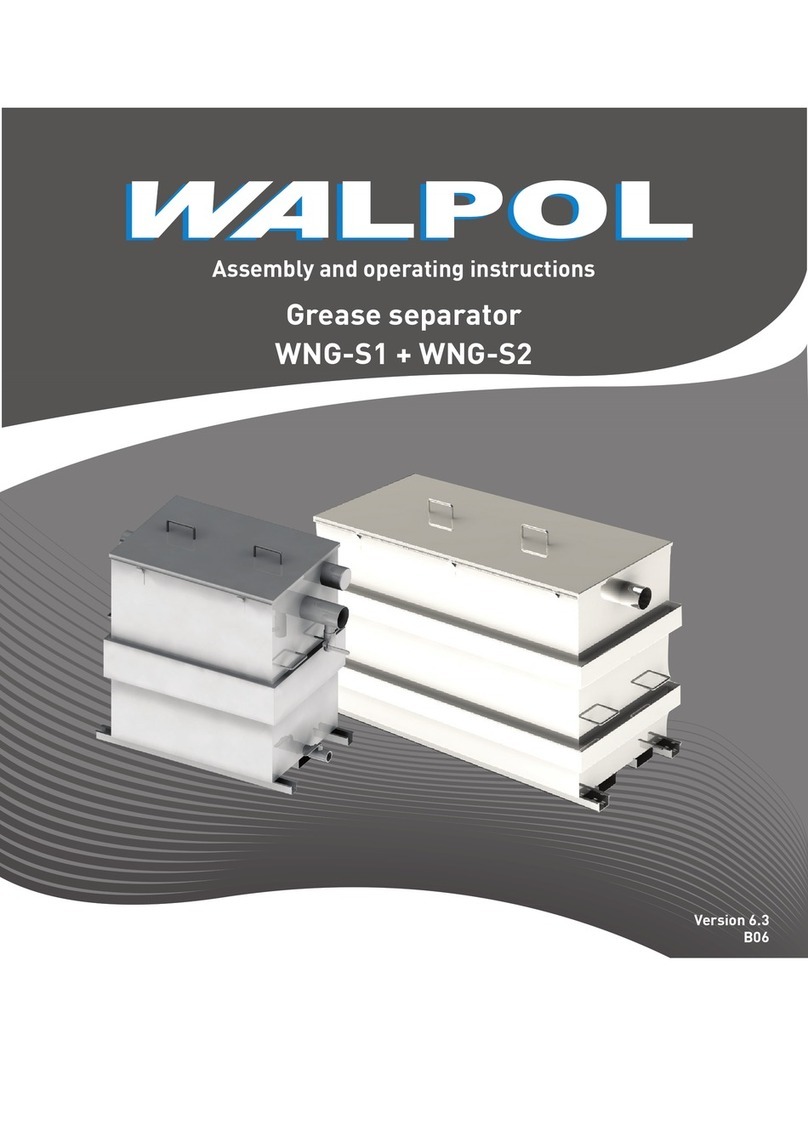
Grease separator
WNG-S1 + WNG-S2
Installation and operating instructions

2
1. General information 3
1.1. Notice Symbols 3
2. Important safety information 3
2.1. General notes (excerpt of DIN EN 1825-2) 3
2.2. Technical regulations to be observed: 4
2.3. Personnel 4
2.4. Personal protective equipment 4
2.5. Foreseeable misuse 4
3. Guarantee 5
4. Delivery, transport, storage 5
5. Description 6
5.1. Grease separator WNG-S1/S2 6
5.2. Specifications of the grease separator 6
5.3. Intended Use 7
6. Installation 7
6.1. Installation site / requirements 7
6.2. Mounting 7
6.3. Backflow-free installation 7
6.4. Ventilation duct 8
6.5. First filling and pressure test 8
7. Operation 8
7.1. Foreseeable misuse 8
7.2. Liability 8
7.3. Recommendation 8
7.4. Violations 9
7.5. Hazards arising from the product 9
Contents
8. Emptying 9
8.1. Manual (without direct disposal pipe) 9
8.2. Emptying with direct disposal pipe 9
9. Cleaning 9
10. Decommissioning / shutdown / storage 10
11. Operation log 10
12. Declaration of performance 12
12.1. WNG-S1 12
12.2. WNG-S2 12
13. Declaration of Conformity 13
14. Certificate 15
14.1. Grease separator WNG-S1 15
14.2. Grease separator WNG-S2 19

3
1. General information
For reasons of clarity, this operating manual does not contain all the detailed information and can not cover every concei-
vable case of adjustment, operation or maintenance.
Should you require further information or problems occur that are not listed in the operating instructions, please contact
our customer service with confidence. Changes that serve technical progress are reserved!
1.1. Notice Symbols
Gefahr
Direct hazard
Failure to comply with this warning will lead directly
to death or serious injury.
Caution
Hazard with a low risk
Failure to comply with this warning may lead to
moderate injuries.
Warning
Potential hazard
Failure to comply with this warning may lead to death
or serious injury.
Important
Hazard with risk of damage to objects
Failure to comply with this warning will lead to
damage to objects
Note
Useful information and instructions.
2. Important safety information
Planners, property owners, specialist companies and operators must then prove that all standards, guidelines, laws have
been observed.
• Read the operating instructions completely and carefully.
• Keep the operating instructions and other valid documents with the grease separator. They must always be available at
the place of use.
• Observe and respect local conditions, regulations and laws
• Abide by the system-related conditions and requirements of the system manufacturer or plant constructor
• The grease separator may only be used if it is in perfect condition.
• The generally prescribed electrical and mechanical protective devices must be provided.
• During assembly, electrical connection, commissioning, troubleshooting, debugging and maintenance, secure the
assembly site and the premises to prevent unauthorized access.
• Make sure that all warning labels on the grease separator are complete and legible.
• This device is not intended for use by persons (including children) with limited physical or mental capabilities or
without experience and prior knowledge, unless such persons have been instructed in the use of the device by a
person responsible for their safety.
• Children are not allowed to play with the device.
2.1. General notes (excerpt of DIN EN 1825-2)
• Only waste water containing fats and oils of vegetable and animal origin may be discharged into the grease separator.
• Existing drainage pipes must be checked for a suitable connection height.
• The materials of the inlet and outlet pipes must comply with DIN EN 12056 and be resistant to waste water in
accordance with DIN EN 1825-2. The required pipe cross-section depending on the nominal size of the separator must
be observed.
• The wastewater is to be fed to the separator system in a free gradient. If the still water level of the separator is below
the backflow level (see EN752-2), water must be drained using a lifting system.
• In order to prevent grease deposits in the supply lines to the grease separator, they must be laid with a gradient of at
least 2% (1:50) and must be easy to clean.

4
2.2. Technical regulations to be observed:
• DIN 1986 drainage systems for buildings and properties, part 30. 100
• DIN EN 752 drainage systems outside of buildings. Part 1-7
• DIN EN 1825 separator systems for grease, part 2
• Draft DIN 4040, part 100
• DIN EN 12056 gravity drainage systems inside buildings, part 1-5
• DIN 1988 Technical rule for drinking water installations
Warning
The machine / system described in the operating instructions was built in accordance with the latest technology and is
safe to operate. It corresponds to the applicable EU directives. Gefahr spots are secured according to the accident
prevention regulations. However, danger can arise from the machine / system if it is used improperly by untrained
personnel or for improper use. Danger to life, danger for the machine / system and danger for the efficient work of the
machine can then arise.
2.3. Personnel
The grease separator may only be operated by qualified, instructed and trained personnel. These persons must know the
relevant safety regulations in order to recognize and avoid possible dangers. The individual actions and qualifications can be
found in Table 1 Qualification.
Danger
Untrained, unqualified or untrained personnel must not operate the machine / system!
The personnel for operation, maintenance and repair must have the appropriate qualifications for this work and be familiar
with the installation, operation and maintenance instructions, in particular with regard to the instructions contained therein
and the applicable regulations on occupational safety and accident prevention.
Table 1 Qualification
Actions Qualification
Storage, operation, transport, cleaning,
disposal
Trained personnel (see following note)
Commissioning assembly Specialists or persons with appropriate
qualifications
Installation, dismantling Assembly specialists or persons with the
appropriate qualifications
Maintenance Assembly specialist or persons with
corresponding qualifications
Repairing Assembly specialists or persons with
appropriate qualifications
Note
The owner must ensure that the personnel have been trained in the operation
and understand the operating instructions.
2.4. Personal protective equipment
Protective equipment must be worn for all work in the vicinity of the grease separator.
• Protective clothing
• Safety shoes
• Protective gloves
• safety goggles
2.5. Foreseeable misuse
• The grease separator may only be operated by someone who has read and understood the operating manual.
• People who are under medication or other drugs are not allowed to operate or maintain the system or perform any
other work on it.

5
3. Guarantee
See AGB Walpol Katalog or go to our website: www.walpol.eu
Unauthorized changes to the machine exclude any liability on the part of the manufacturer for any resulting damage. If the
machine is operated improperly, not as intended or by untrained personnel, the following dangers may arise:
• Danger to life
• Danger to the machine and other assets of the owner,
• Danger to the efficient work of the machine
To assert warranty claims, the products must be properly connected and operated and used in accordance with the data
sheets. A prerequisite is a fully completed operating diary, which can be requested from Walpol in the event of a warranty
claim. The operating log is part of this document, the maintenance plan must be created by the operator.
4. Delivery, transport, storage
Securitynote:
Warning: Suspended loads
• Protective equipment must be worn for all work in the vicinity of the grease separator, see 2.4 Personal protective
equipment,
• Never step under a suspended load.
• It must be ensured that nobody is under a suspended load.
Delivery
Every grease separator leaves our factory in a mechanically perfect condition. It is recommended to transport the grease
separator in its original packaging to the installation site.
Check delivery
• Check the packaging for transport damage. Any damage must be noted in the cargo register.
• Check whether the delivery is complete.
Unpacking
Warning
When removing the transport packaging, there is a risk of damage from sharp edges, nails, staples, splinters, etc.
• Carefully unpack the grease separator.
• Check the grease separator for obvious transport damage.
• Do not remove the packaging until shortly before installation.
• Protective equipment must be worn for all work in the vicinity of the grease separator, see . Personal protec-
tive equipment
Transport
Securitynote:
Caution: Careless loading or unloading can damage the grease separator.
• Carry out loading or unloading carefully.
• Use lifting equipment suitable for the load.
• Observe the transport arrows on the packaging.
• The packaging serves only as transport protection and must not be used for lifting.
Storage
• Store the grease separator in the original packaging in a dry, dust-free place that is protected from weather effects.
• Avoid extreme heat or cold.

6
5. Description
5.1. Grease separator WNG-S1/S2
A grease separator is used wherever greasy wastewater is to be expected. The grease separator separates fats, oils and
sludge from the wastewater. Thanks to the flushing and disposal device, the grease separator can be disposed of with
almost no odor nuisance, since the odor-tight closed system does not have to be opened for this. The hose of the disposal
vehicle can be connected to the permanently installed disposal line, which is led to an easily accessible point. The separa-
ted fats are pumped directly into the disposal vehicle. This eliminates the time-consuming and unhygienic laying out of the
disposal hoses through utility and storage rooms (e.g. food areas). In addition, there is no odor nuisance there
5.2. Specifications of the grease separator
Typ WNG-S1
Sludge trap 100 liter
Grease separation capacity 120 liter
Weight 103kg
600
1150
850
1015
easy transport with
pallet truck
Intake
DN 100
Drainage
Connection possibility
for venting
Outlet DN 100
Drainage
Typ WNG-S2
Sludge trap 200 liter
Grease separation capacity 482 liter
Weight 143kg
1790
1688
1020
1490690
easy transport with
pallet truck
Intake
DN 100
Drainage
Connection possibility
for venting
Outlet DN 100
Drainage

7
5. Description
5.1. Grease separator WNG-S1/S2
A grease separator is used wherever greasy wastewater is to be expected. The grease separator separates fats, oils and
sludge from the wastewater. Thanks to the flushing and disposal device, the grease separator can be disposed of with
almost no odor nuisance, since the odor-tight closed system does not have to be opened for this. The hose of the disposal
vehicle can be connected to the permanently installed disposal line, which is led to an easily accessible point. The separa-
ted fats are pumped directly into the disposal vehicle. This eliminates the time-consuming and unhygienic laying out of the
disposal hoses through utility and storage rooms (e.g. food areas). In addition, there is no odor nuisance there
5.2. Specifications of the grease separator
Typ WNG-S1
Sludge trap 100 liter
Grease separation capacity 120 liter
Weight 103kg
600
1150
850
1015
easy transport with
pallet truck
Intake
DN 100
Drainage
Connection possibility
for venting
Outlet DN 100
Drainage
Typ WNG-S2
Sludge trap 200 liter
Grease separation capacity 482 liter
Weight 143kg
1790
1688
1020
1490690
easy transport with
pallet truck
Intake
DN 100
Drainage
Connection possibility
for venting
Outlet DN 100
Drainage
5.3. Intended Use
The separator system is intended exclusively for the separation of saponifiable oils and fats of vegetable and animal origin.
Any use going beyond this is considered improper. The manufacturer is not liable for any resulting damage; the user alone
bears the risk!
Animal and vegetable oils and fats must not be discharged into public waste disposal facilities or waters, as they cause
cross-sectional constrictions and blockages in the disposal lines when cold. Furthermore, after a short decomposition
time, fatty acids are formed, which lead to unpleasant odors and attack pipes and structures in the drainage system. The
solidified layer of fat on the surface of the water also inhibits the necessary oxygen supply in waters and sewage treatment
plants. In addition, DIN1986 Part 1 requires the retention of harmful substances. For these reasons, grease separator sys-
tems must be provided that must be disposed of accordingly. The temperature in the separator should be as low as possib-
le. With an increase of 10 ° C the separation efficiency is halved.
Compliance with the operating, maintenance and repair conditions prescribed by the manufacturer is also part of the inten-
ded use.
6. Installation
6.1. Installation site / requirements
Free-standing installation in frost-free rooms
Before installing the grease separator, check the following:
Separation systems should be installed near where the waste water occurs. Furthermore, the suction connection for clea-
ning vehicles should be easily accessible.
• The system should not be set up in the vicinity of common rooms, especially not in the vicinity of windows or ventilation
openings, so that unpleasant smells are avoided
• It is easy to reach for cleaning vehicles
• Room with good air circulation and / or ventilation as well as an even and sufficiently stable installation surface
(observe stability / ceiling load)
• Room temperature at least 15°C.
• Sealed floor covering with integrated drainage point.
• Hot and cold water connection
• Room height at least 60 cm higher than the grease separator system, so that the revision lid can be opened during
cleaning work.
• Free working space, at least 1 m, in front of the grease separator system.
• The wastewater is to be fed to the separator system for grease in a free gradient
• Inlet with calming section of min. 1 m (slope 1:50). Transition from on-site downpipe to the calming section equipped
with 2x 45° bends DN 250 at least
• If the supply line is longer than 10 m, it must be vented separately.
• Foreign objects (cutlery, crown corks, mustard bags, bones, etc.) interfere with the separation process
• In areas at risk of flooding, the system can be secured against floating
6.2. Mounting
• Install inlet and outlet
• Establish pipe connections to the house installation at the inlet and outlet.
• Make sure that the seals are sufficiently greased.
• The pipe materials used should be resistant to animal and vegetable fats, oils and their degradation products (seal
made of NBR, high temperatures).
Immediately at the outlet of the separator and before mixing with other wastewater, a device for sampling and inspection
must be installed (depending on the version already included in the scope of delivery)
The sampling point or facility of the separator system must be freely accessible and arranged in such a way that only
wastewater that has passed through the separator system is sampled
6.3. Backflow-free installation
Separator systems for fats whose still water level is below the backflow level must be drained via downstream lifting
systems
• Where aplicable mount the direct disposal pipe - The disposal pipe provided for emptying should have a diameter of at
least 50 mm inside width
• The choice of the pipe material for the disposal line should be based on the waste water content (extremely high solid
content) and the particular operating situation (overpressure / underpressure).
• The disposal line from the grease separator to the transfer point to the disposal vehicle should be laid with a steadily
rising gradient. Changes in the direction of the line through 90 ° bends should be carried out with a large radius if
possible

8
• The disposal line must be able to be closed odor-tight (e.g. Storz-B coupling).
• Use tensile strength connections between the individual pipes and fittings
6.4. Ventilation duct
• The inlet and outlet lines on separator systems for grease must be adequately ventilated
• For this purpose, the inlet pipe is to be run as a ventilation pipe over the roof. All connection lines longer than 5 m
must be vented separately
• No other ventilation systems may be connected to these ventilation lines
• The ventilation line of the supply line and, if necessary, the grease separator can be combined to a collective ventilation
system
6.5. First filling and pressure test
• Make sure that there are no foreign substances or impurities in the grease separator.
• Fill the entire grease separator system completely with water.
• Carry out a pressure test by opening both inspection lids.
• Close the outlet and inlet with appropriate means.
• Fill the grease separator system completely with water and ensure that there are no leaks.
• Restore the functionality of the outlet and inlet.
The operational readiness is established.
7. Operation
If the machine is operated outside of Germany, the safety regulations in the country of use are also
relevant.
Relevant regulations and rules must be observed:
• Accident prevention regulations
• Other generally recognized safety, occupational medicine and road traffic regulations
Important
Observe the rules for safe and professional work
In addition to the operating instructions and the accident prevention regulations applicable in the country of use and at
the place of use, the recognized technical rules for safe and professional work must also be observed.
The permissible loads on the grease separator system must not be exceeded!!
7.1. Foreseeable misuse
The grease separator may only be operated by someone who has read and understood the operating manual.
People who are under medication or other drugs are not allowed to operate or maintain the system or carry out other
activities on it.
7.2. Liability
With the machine acceptance, the operator confirms that the supplier has fulfilled all due diligence obligations within the
scope of what is possible and reasonable.
We are liable for defects in the delivery according to the conditions agreed in the order confirmation.
The rectification of defects may only be carried out by qualified personnel.
Our liability is limited to damage caused by normal use.
We are not liable for security deficiencies that are not yet recognizable according to the current state of technology.
7.3. Recommendation
• Components and accessories are designed exclusively for this product.
• When purchasing spare or wear parts, only original parts are to be used.
• We expressly point out that parts and accessories not supplied by us have not been tested and approved by us. The
installation and / or use of such products can negatively affect the system‘s structural properties and thereby impair
active and / or passive operational safety.
The following excludes our liability for consequences::

9
7.4. Violations
• against safety instructions
• against the information on special dangers,
• against the prohibition of unauthorized conversions and changes.
If damage occurs within the guarantee period, the cause of which is doubtful and for which you would like to assert gua-
rantee claims, we ask you to notify WALPOL immediately and to await further instructions.
Until the cause has been clarified or we have approved it, the separator system must be left in the state in which it was left
due to the damage.
Regardless of this, you must first secure the scene of the accident in order to avoid consequential damage.
Prohibition of unauthorized changes and modifications:
The machine may - without our consent - be changed neither structurally nor in terms of safety. Any unauthorized change
in this sense excludes any liability on our part..
7.5. Hazards arising from the product
• Danger of slipping when emptying the system
During cleaning work, fatty liquids and / or fat can wet the floor. This creates a risk of slipping. Immediately remove any
leaked liquid and / or fat and wear suitable footwear.
• Risk of infection in contact with sewage
The wastewater contains bacteria. There is a risk of infection if it comes into contact with mucous membranes, eyes,
wounds or if it gets into the body. Immediately clean body parts that have come into contact with waste water, change conta-
minated clothing. Wear personal protective equipment.
8. Emptying
8.1. Manual (without direct disposal pipe)
• To empty the grease separator, first open the container lids. It is then emptied by suctioning off the entire contents of
the grease separator through the suction hose of the disposal tanker.
• The grease separator must be completely cleaned after emptying and then refilled with fresh water up to the overflow.
• The system is emptied and cleaned at regular intervals at least once a month in accordance with DIN 4010-100.
• If the maximum storage capacity of grease and / or sludge trap is reached prematurely, the grease separator must be
completely emptied and cleaned at once.
8.2. Emptying with direct disposal pipe
(Creation on site if necessary)
• Where aplicable mount the direct disposal pipe - The disposal pipe provided for emptying should have a diameter of at
least 50 mm inside width
• The choice of the pipe material for the disposal line should be based on the waste water content (extremely high solid
content) and the particular operating situation (overpressure / underpressure).
• The disposal line from the grease separator to the transfer point to the disposal vehicle should be laid with a steadily
rising gradient. Changes in the direction of the line through 90 ° bends should be carried out with a large radius if
possible
• The disposal line must be able to be closed odor-tight (creation on site if necessary).
• Use tensile strength connections between the individual pipes and fittings
• Open the inspection lid.
• Connect the suction hose of the disposal vehicle to the direct disposal pipe (connection and coupling must be created
on site)
• Empty the system tank (suction).
• When the system tank is approx. 1 third empty, open the hot water supply.
• When the system tank is completely emptied, dismantle the suction hose from the disposal vehicle and switch off the
hot water supply.
• Clean the system tank (hose out).
9. Cleaning
Inside cleaning of the container:
• Open the container lid
• Thorough cleaning of all lines (inlet, outlet with integrated sampling point, ventilation lines) with a high-pressure
cleaner

10
• Thorough cleaning of the interior of the container, also using a high pressure cleaner.
External cleaning of the container:
• Depending on the degree of soiling with a high-pressure cleaner
• For final cleaning, the grease separator system is rubbed off from the outside with care oil for stainless steel.
• After performing the above and before starting work again, the system must be filled with water and then checked for
leaks.
10. Decommissioning / shutdown / storage
• The machine must be cleaned before storage
• Bare surfaces of machine components must be treated with corrosion protection.
• The transport locks must be attached. Movable machine parts are to be fixed
• The grease separator and its components must be stored in a dry, evenly air-conditioned room, never outdoors
• The required floor load capacity according to the weights of the machine components and individual parts must be
observed
11. Operation log
Grease separator Series WNG-S2
The dates and results of the self-checks, maintenance and inspections carried out, the disposal of removed ingredients
(filing of the disposal evidence from the disposal company) as well as the elimination of any deficiencies are to be documen-
ted in the operating log. The operating log and test reports are to be kept by the operator and, upon request, shown to the
locally responsible supervisory authorities or the operators of the municipal sewage systems.
Note
The timely and regular emptying, cleaning and maintenance of the grease separator system
guarantees perfect functioning.
Important
Emptying and cleaning intervals
Kitchen fats and oils form fatty acids within a very short time, which must not get into the sewage system. Accordingly
the emptying and cleaning intervals are to be determined so that the storage capacity of the separator and the sludge
trap is not exceeded.
Unless otherwise requirde by ordinances and other requirements, cleaning and maintenance must be carried out in accor-
dance with the operating instructions.
Maintenance must be carried out by qualified professionals.

11
Operation log
Grease separator TYP S2
Certificate 01130/19/Z00NZK ITB institut
Commissioning company: Date:
Nr. Date
Emptying /
Name of disposal company
Maintenance/self-check
(acc. to manual)
Signature
(disposal company)

12
12. Declaration of performance
12.1. WNG-S1
1. Unique identification code of the product type:
• Separator systems for grease made of stainless steel with integrated sludge trap (see annex to the declaration of
performance
2. Type, batch or serial number or other means of identifying the product in accordance with Article 11 paragraph 4:
• Grease separator type S1
3. Intended use of the product as intended by the manufacturer in accordance with the applicable harmonized technical
specification:
• Separator system for separating fats and oils of vegetable and animal origin from wastewater due to gravity without
the influence of external energy.
4. Name, registered trade name or registered brand and contact address of the manufacturer:
Walpol GmbH
Benzstr. 13
45891 Gelsenkirchen
5. If applicable Name and contact address of the authorized representative who is entrusted with the tasks in accordance
with Article 12 paragraph 2:
• not applicable
6. System or systems for assessing and checking the constancy of performance of the product in accordance with
Annex V:
• Certificate by OLAN Projects 17.02.2021
7. In the case of the declaration of performance that concerns a product that is covered by a harmonized standard:
• factory production control
• Certificate by OLAN Projects 17.02.2021
8. In the case of the declaration of performance relating to a product for which a European Technical Assessment has
been issued:
• not applicable
9. Declared performance:
Main features Result harmonized technical specification
Fire behavior Passed
EN -:
Liquid tightness Passed
Effectiveness Passed
Load capacity Passed
Durability Passed
12.2. WNG-S2
1. Unique identification code of the product type:
• Separator systems for grease made of stainless steel with integrated sludge trap (see annex to the declaration of
performance
2. Type, batch or serial number or other means of identifying the product in accordance with Article 11 paragraph 4:
• Grease separator type S2
3. Intended use of the product as intended by the manufacturer in accordance with the applicable harmonized technical
specification:
• Separator system for separating fats and oils of vegetable and animal origin from wastewater due to gravity without
the influence of external energy.
4. Name, registered trade name or registered brand and contact address of the manufacturer:
Walpol GmbH
Benzstr. 13
45891 Gelsenkirchen

13
5. If applicable Name and contact address of the authorized representative who is entrusted with the tasks in accordance
with Article 12 paragraph 2:
• not applicable
6. System or systems for assessing and checking the constancy of performance of the product in accordance with
Annex V:
• Certificate ITB test mark 01130/19 / Z00NZK
7. In the case of the declaration of performance that concerns a product that is covered by a harmonized standard:
• factory production control
• Certificate ITB test sign 01130/19 / Z00NZK
8. In the case of the declaration of performance relating to a product for which a European Technical Assessment has
been issued:
• not applicable
9. Declared performance:
Main features Result harmonized technical specification
Fire behavior Passed
EN -:
Liquid tightness Passed
Effectiveness Passed
Load capacity Passed
Durability Passed
The manufacturer is solely responsible for this declaration of performance.
Signed for and on behalf of the manufacturer by:
Place: Gelsenkirchen
Date: 1.12.2021
Maximilian Girnus
Executive Director WALPOL GmbH
13. Declaration of Conformity
According to Maschinenrichtlinie 2006/42/EG Anhang II 1A.
The manufacturer
Manufacturer: Walpol GmbH
Benzstr.
Gelsenkirchen - Germany
hereby declares that the machine described below
Product name: Separator system for grease made of stainless steel
AISI with integrated sludge trap
Type: WNG-S NS
WNG-S NS
complies with all relevant provisions of the above-mentioned directive, including any changes applicable at the time of the
declaration.
further applied directive: Bauproduktrichtlinie //EWG

14
The following harmonized standards were applied:
EN ISO : Sicherheit von Maschinen - Allgemeine Gestaltungsleitsätze
- Risikobeurteilung und Risikominderung
EN ISO -: Sicherheit von Maschinen - Sicherheitsbezogene Teile von
Steuerungen - Teil : Allgemeine Gestaltungsleitsätze
EN ISO -: Sicherheit von Maschinen - Elektrische Ausrüstung von
Maschinen - Teil : Allgemeine Anforderungen
EN ISO -: Abscheideranlage für Fette - Teil : Bau-, Funktions- und
Prüfgrundsätze, Kennzeichnung und Güteüberwachung
The stainless steel material used meets the requirements of fire behavior class A1.
The designated separator systems are intended for the separation by gravity of fats of vegetable and / or animal origin
from waste water to protect drainage systems.
Place: Gelsenkirchen
Date: 1.12.2021
Maximilian Girnus
Executive Director WALPOL GmbH
Information on CE sign in the accompanying documents
Walpol GmbH
Benzstr.
Gelsenkirchen
EN ISO -:
Separator system for grease with
integrated sludge trap
Information on CE sign of separator system for grease
Walpol GmbH
EN

15
14. Certificate
14.1. Grease separator WNG-S1
Scientific and technical report on the load capacity and stability of the grease separator made of acid-resistant
steell
OLAN Projects 17.02.2021
Note
Below the original certificate in german.
For further information please contact WALPOL.
Seite 1 von 7
Wissenschaftlich-technisches Gutachten zur
Tragfähigkeit und Stabilität eines Fettabscheiders aus
säurebeständigem Stahl
17.02.2021 Leszno
Planungsbüro Biuro Konstruktorskie OLAN Projects
Ul.Kasztanowa 11
05-084 Wilkowa Wieś
Tel. +48.509.452.425
www.olanprojects.e
u NIP: 9372201372
Auftraggeber: Walpol Polska Sp. z o.o. Warszawska 3, 05-084 Leszno
Auftragnehmer: Dipl. Ing. Henryk Kos
Überprüfung: Dr. hab. Ing. Ireneusz Wróbel

16
Seite 2 von 7
Inhaltsverzeichnis
1. Zweck und Umfang des Gutachtens.................................................................................. 2
2. Verwendete Materialien ...................................................................................................... 2
3. Beschreibung der Abscheiderkonstruktion...................................................................... 3
4. Annahmen zur statischen Festigkeitsanalyse ................................................................. 4
5. Analyseergebnisse ............................................................................................................. 6
6. Schlussfolgerungen ............................................................................................................ 7
1.
Zweck und Umfang des Gutachtens
Zweck des Gutachtens ist es, zu überprüfen, ob die Konstruktion des Abscheiders
ausreichende Tragfähigkeit hat - und damit die Sicherheit der Verwendung des Produkts
gewährleistet.
Der Umfang des Gutachtens umfasst folgende Forschungsaktivitäten:
1. Analyse der bereitgestellten technischen Dokumentation
2. Ermittlung der auf den Fettabscheider wirkenden Kräfte
3. Bau eines FEM-Modells des Abscheiders auf Basis der bereitgestellten Geometrie
4. Statische Festigkeitsanalyse
5. Gutachten zur Tragfähigkeit und Stabilität der Abscheiderkonstruktion
6. Schlussfolgerungen
Dieses Gutachten betrifft ausschließlich die Konstruktions- und Festigkeitsfragen, es bezieht
sich nicht auf die Fertigungstechnologie des Fettabscheiders.
2.
Verwendete Materialien
[1] PN-EN 1990 Eurocode 0: Grundlagen der Tragwerksplanung.
[2] PN-EN 1991-1-1 Eurocode 1: Einwirkungen auf Tragwerke. Teil 1-1
Allgemeine Einwirkungen - Wichten, Eigengewicht, Nutzlasten im Hochbau.
[3] PN-EN 1993-1-1 Eurocode 3: Bemessung und Konstruktion von Stahlbauten -
Teil 1-1: Allgemeine Bemessungsregeln und Regeln für den Hochbau.
[4] PN-EN 10088-1 Nichtrostende Stähle - Teil 1: Verzeichnis der nichtrostenden Stähle.
Seite 3 von 7
[5] PN-EN 10088-2 Nichtrostende Stähle - Teil 2: Technische Lieferbedingungen
für Blech und Band aus korrosionsbeständigen Stählen für allgemeine
Verwendung.
[6] Zeichnungsdokumentation und dreidimensionale Geometrie, die vom
Auftraggeber bereitgestellt wurden.
[7] E-Mail-Schriftverkehr
3.
Beschreibung der Abscheiderkonstruktion
Der Abscheider, der auf der Zeichnung 1 dargestellt ist, hat die Form eines Quaders
mit den Abmessungen 600 x 1850 x 970 mm (B x L x H). Er wurde aus 2 mm dickem
säurebeständigem Stahl 1.4301 nach PN-EN 10088-1 gefertigt. Die Abscheiderwände sind mit
einem Band verstärkt. Die Geometrie des Abscheiders wurde vom Auftraggeber übergeben.
Der Abscheider wird im Innenbereich eingesetzt.
Verstärkungsband
Abb. 1 Abscheidermodell

17
Seite 5 von 7
Die GZG-Bedienung wurde durch den Vergleich der maximalen Durchbiegung der
Behälterwände mit den zulässigen Werten geprüft (angenommen L/200, wobei L ist die kürzere
Seite der Wand).
4.4. Beschreibung des Rechenmodells
Die Berechnungen des Abscheiders wurden mit der Finite-Elemente-Methode durchgeführt.
Die vom Kunden bereitgestellte Geometrie wurde in das FEM-System eingeführt. Der
Abscheider wurde mit flachen Vier-Knoten-Finite-Elementen modelliert. An den Füßen des
Unterbaus wurde verhindert, dass es zur Verschiebung in vertikaler Richtung kommt. An die
Behälterwände kam von Innen hydrostatischer Druck (Flüssigkeitsdichte wurde gemäß
Abschnitt 3.1 angenommen). Bei den Berechnungen wurde auch das Eigengewicht der
Konstruktion berücksichtigt. Geometrische Nichtlinearität (große Verformungen) wurde bei den
Berechnungen berücksichtigt. Die numerischen Modelle wurden weder validiert noch kalibriert,
so dass die Ergebnisse der Berechnungen nicht mit den Ergebnissen von Tests an realen
Objekten gleichgesetzt werden können. In Wirklichkeit können die Werte von Lasten,
Verschiebungen und Verformungen etwas anders sein. Abbildung 2 zeigt das diskrete FEN-
Modell des Abscheiders, die Werte des auf den Abscheider wirkenden hydrostatischen Drucks
und wie das Modell abgestützt wird.
Diskretes FEM-Modell hydrostatischer Druck Abstützung des Modells
Abb. 2 Diskretes Modell sowie Randbedingungen der Aufgabe
Seite 4 von 7
4.
Annahmen zur statischen Festigkeitsanalyse
4.1. Auf den Abscheider wirkende Kräfte
In den numerischen Berechnungen wurden folgende Belastungen berücksichtigt:
•Druck der Flüssigkeit an den Wänden des Abscheiders - U
Bei den Berechnungen wurde angenommen, dass sich der Abscheider bis zur Höhe der
Oberkante mit Wasser füllt. Angenommene Wasserdichte: rw= 1000 kg/m3
Für den charakteristischen Wert der Einwirkung wurde der Grenzzustand der
Gebrauchstauglichkeit (GZG) und für den Bemessungswert der Einwirkung wurde die
Bedingung des Grenzzustands der Tragfähigkeit (GZT) nachgewiesen (für die Einwirkungen
wurde 1,5-Faktor nach [1] angenommen):
rz= 1,5 * 10 kg/m3 = 1500 kg/m3.
Für die FEM-Analyse des Abscheiders wurde folgende äquivalente Dichte angenommen: rz= 1500
kg/m3
4.2. Mechanische Parameter des Stahls, die bei der Analyse angenommen wurden
Für die Berechnungen wurden folgende mechanische Parameter des rostfreien Stahls 1.4301
nach PN-EN 10088-1 und 2 ([4], [5]) angenommen:
•Elastizitätsmodul E = 194 [GPa],
•Poissonzahl v = 0,3,
•spezifisches Gewicht r = 7900 [kg/m3],
•charakteristische Werte der konventionellen Streckgrenze (Ra) und Zugfestigkeit (Rm):
Ra = 230 [MPa] und Rm = 540 [MPa].
4.3. Bedingungen für Grenzzustände
Der Nachweis der GZT-Bedienung erfolgte wie folgt:
•Vergleich der maximalen reduzierten Spannung HMH infolge von Einwirkungen mit
Bemessungswerten mit der konventionellen Streckgrenze von Stahl (Teilsicherheitsbeiwert YMI
= 1,0 wurde nach PN-EN 1993-1 angenommen),
•Nachweis der Möglichkeit des Stabilitätsverlustes der Abscheiderwände (unter
Berücksichtigung der geometrischen Nichtlinearität in der Analyse).

18
Seite 6 von 7
5.
Analyseergebnisse
Abbildung 3 zeigt die Spannungsschichtung nach von Mises, die in der Abscheiderkonstruktion
unter hydrostatischem Druck auftritt.
Abb. 3 Reduzierte Spannungsschichtung nach von Mises in MPa
Bei der Analyse der in Abbildung 3 dargestellten Ergebnisse kann festgestellt werden, dass die
maximale reduzierte Spannung sred = 131 MPa<Ra=230 MPa beträgt.
Der Sicherheitsfaktor ist =
Die Stabilität der Abscheiderwände wird nicht beeinträchtigt. Die GZT-Bedingung ist erfüllt.
Seite 7 von 7
Auf der Abbildung 4 sind die Verformungsschichten des
Separators dargestellt.
Abb. 3 Verformungsschichten des Separators in mm
Bei der Analyse der in Abb. 4 dargestellten Ergebnisse kann festgestellt werden, dass die maximalen
Verformungen (Durchbiegungen) des Behälters w =3.2 mm betragen. Grenzwert der Durchbiegung
W=3,2 mm < Wdop = 4,85 mm
Die Bedingung für die Durchbiegungsgrenzen (GZG) wurde erfüllt.
6.
Schlussfolgerungen
In Anbetracht der Ergebnisse der durchgeführten FEM-Analysen kann festgestellt werden, dass:
- die maximalen Spannungen in den Abscheiderwänden die zulässigen Werte nicht
überschreiten – die GZT-Bedingung ist erfüllt,
- die höchsten Durchbiegungswerte der Behälterwände keine Grenzwerte überschreiten - die
GZG-Bedingung ist erfüllt.
Erstellt Geprüft
Dipl. Ing. Henryk Kos Dr. hab. Ing. Ireneusz Wróbel

19
mgr Iwona Wiśniewska
Beeidigte Dolmetscherin und Übersetzerin für die deutsche Sprache
in die Liste der vereidigten Dolmetscher und Übersetzer des Justizministers von Polen
unter der Nummer TP/2009/06 eingetragen
Handy: +48 501 088 676
Anstalt für Baukonstruktionen, Geotechnik und Beton
GUTACHTEN 01130/19/ZOONZK
1
Beglaubigte Übersetzung aus der polnischen Sprache Nr. N/8/2019
[Das Originaldokument wurde auf acht Seiten angefertigt und wurde mir in Form von
einem Scan zu Verfügung gestellt. Die Anmerkungen der Übersetzerin wurden in
Kursivschrift erstellt und in Eckklammern gesetzt.]
ITB - INSTITUT FÜR BAUTECHNIK
00-611 Warszawa, ul. Filtrowa 1, tel. 825-04-71, Fax 825-52-86
01130/19/Z00NZK
Wissenschaftliches und technisches Gutachten zur Tragfähigkeit und Stabilität
des Fettabscheiders aus säurebeständigem Stahl
Warschau, April 2019
mgr Iwona Wiśniewska
Beeidigte Dolmetscherin und Übersetzerin für die deutsche Sprache
in die Liste der vereidigten Dolmetscher und Übersetzer des Justizministers von Polen
unter der Nummer TP/2009/06 eingetragen
Handy: +48 501 088 676
Anstalt für Baukonstruktionen, Geotechnik und Beton
GUTACHTEN 01130/19/ZOONZK
2
ITB - INSTITUT FÜR BAUTECHNIK
00-611 Warszawa, ul. Filtrowa 1
Telefon: (0
-22) 825-80-28 Fax: (0-22)579-61-89
Anstalt für Baukonstruktionen, Geotechnik und Beton
Titel der Arbeit: Wissenschaftliches und technisches Gutachten zur Tragfähigkeit und
Stabilität eines Fettabscheiders aus säurebeständigem Sahl
Nummer der Dienstleistung:
01130/19 / Z00NZK
Auftraggeber:
Walpol Polska sp. z o.o., Wojska Polskiego 4,
-084 Leszno
Au
sführender: Dipl.-Ing. Sławomir Dudziak
Üb
erprüfung: Dr. Ing. Jarosław Szulc
Leitet der
Anstalt: Dr. Ing. Artur Piekarczuk
Beginn der
Arbeit: März 2019.
Ende der
Arbeit: April 2019.
Die Arbeit wurde in 4 Ausfertigungen erstellt,
14.2. Grease separator WNG-S2
Certification sign 01130/19 / Z00NZK
Scientific and technical report on the load capacity and stability of the grease separator made of acid-resistant
steel
Note
Below the original certificate in german.
For further information please contact WALPOL.

20
mgr Iwona Wiśniewska
Beeidigte Dolmetscherin und Übersetzerin für die deutsche Sprache
in die Liste der vereidigten Dolmetscher und Übersetzer des Justizministers von Polen
unter der Nummer TP/2009/06 eingetragen
Handy: +48 501 088 676
Anstalt für Baukonstruktionen, Geotechnik und Beton
GUTACHTEN 01130/19/ZOONZK
3
Inhaltsverzeichnis
1. Einleitung ...................................................................................................................... 3
1.1. Formale Grundlage und Gegenstand des Gutachtens.......................................................... 3
1.2. Ziel und Umfang des Gutachtens ........................................................................................ 3
1.3. Gebrauchte Materialien .................................................................................................. 4
2. Beschreibung des Fettabscheiders .................................................................................. 4
3. Grundlagen der statistischen Berechnungen............................................................. 5
3.1. Einwirkungen auf den Abscheider ...................................................................................... 5
3.2. Mechanische Parameter von Stahl, von den in der Analyse ausgegangen wurde............... 5
3.3. Grenzzustände - Bedingungen ............................................................................................ 6
3.4. Berechnungsmethode. Beschreibung des numerischen Modells ........................................ 6
4. Statische Analyseergebnisse ........................................................................................ 7
5. Fazit ............................................................................................................................... 9
1. Einleitung
1.1. Formale Grundlage und Gegenstand des Gutachtens
Formale Grundlage des Gutachtens ist der Auftrag von Walpol Polska Sp. z o.o., der in der
Anstalt für Baukonstruktionen, Geotechnik und Beton unter der Nummer 1130/19/Z00NZK
eingetragen wurde.
Gegenstand des Gutachtens ist ein Fettabscheider aus säurebeständigem Stahl mit einem
Fassungsvermögen von ca. 1000 l.
1.2. Ziel und Umfang des Gutachtens
Mit dem Gutachten soll überprüft werden, ob die Konstruktion des Abscheiders eine
ausreichende Tragfähigkeit aufweist, mit der die Einsatzsicherheit des oben genannten
Produktes gewährleistet wird.
Der Geltungsbereich des Gutachtens umfasst folgende Forschungsaktivitäten:
1. Analyse der bereitgestellten technischen Dokumentation
2. Ermittlung der Einwirkungswerte auf den Abscheider
mgr Iwona Wiśniewska
Beeidigte Dolmetscherin und Übersetzerin für die deutsche Sprache
in die Liste der vereidigten Dolmetscher und Übersetzer des Justizministers von Polen
unter der Nummer TP/2009/06 eingetragen
Handy: +48 501 088 676
Anstalt für Baukonstruktionen, Geotechnik und Beton
GUTACHTEN 01130/19/ZOONZK
4
3. Konstruktion eines dreidimensionalen MES-Modells des Fettabscheiders auf
Grundlage der übersendeten Geometrie
4. Statistische Berechnungen der Konstruktion
5. Gutachten zur Tragfähigkeit und Stabilität der Konstruktion des Abscheiders
6. Überprüfung der Arbeit.
Dieses Gutachten befasst sich ausschließlich mit Konstruktionsfragen, nicht mit der Frage der
Produktionstechnologie der Fettabscheider usw.
1.3. Gebrauchte Materialien
[1] PN-EN 1990 Eurocode 0: Grundlagen der Tragwerksplanung.
[2] PN-EN 1991-1-1 Eurocode 1: Allgemeine Einwirkungen auf Tragwerke Teil 1-1 -
Wichten, Eigengewicht und Nutzlasten im Hochbau.
[3] PN-EN 1993-1-1 Eurocode 3: Eurocode 3: Bemessung und Konstruktion von
Stahlbauten - Teil 1-1: Allgemeine Bemessungsregeln und Regeln für den Hochbau
[4] PN-EN 10088-1 Nichtrostende Stähle - Teil 1: Verzeichnis der nichtrostenden Stähle
[5] PN-EN 10088-2 Nichtrostende Stähle - Teil 2: Technische Lieferbedingungen für Blech
und Band aus korrosionsbeständigen Stählen für allgemeine Verwendung;
[6] Zeichnungsdokumentation und dreidimensionale Geometrie des Auftraggebers.
[7] E-Mails
2. Beschreibung des Fettabscheiders
Der Fettabscheider hat die Form eines Quaders mit den Abmessungen 774 x 1756 x 1085 mm
(Breite x Länge x Höhe) und bestent aus 2 mm dickem Blech aus säurebeständigem Stahl mit
der Kennzeichnung 1.4301 gemäß PN-EN 10088-1. Die Wände des Abscheiders sind mit
zwei Rippen verstärkt. Die Geometrie des Abscheiders, die vom Auftraggeber bereitgestellt
wurde, ist in Abbildung 1 dargestellt. Der Abscheider wird in Innenräumen eingesetzt.
Other manuals for WNG-S1
1
This manual suits for next models
1
Table of contents
Other WALPOL Water Filtration System manuals
Popular Water Filtration System manuals by other brands

Waldbeck
Waldbeck 10031071 manual

HealthyAir
HealthyAir HA-SCE-G1 owner's manual

AFRISO
AFRISO FloCo-Top-2 Series operating instructions

Spectra Watermakers
Spectra Watermakers CATALINA 300 MPC-5000 Installation & owner's manual

Ingersoll-Rand
Ingersoll-Rand GP19 instruction manual

fluidra
fluidra AstralPool Viron EQ Installation and operating instructions