Walther prazision 95813 User manual

1
Quick Guide
Installation of the
Tool Parking Station
for Walther Tool Changing System
Type 95813 / 95814 / 95815 /
95816 / 95817 / 95818
Ident-Nr. Dokument 135560 I

2
1 Safety instructions
To obtain warranty, all work has to be done by skilled and trained workers only!
Use only original parts of WALTHER-PRÄZISION to ensure proper operation and function!
The use of this guide does not release the operator from compliance with the relevant industrial safety regulations.
E.g.: Ordinance on Industrial Safety, etc. The operator of a WALTHER tool parking station has the duty to take care
of planning measures to ensure an orderly operation and to monitor their implementation.
The use of the tool parking station in applications where the safety of persons depends on its function
is not admissible. The tool parking station must only be operated when the complete machine / facility corresponds
to the EC-machinery directive!
General safety instructions
- The parking stations must not be put on the floor without protection against dropping or tipping.
- The tool parking stations must only be released from the crane when they are firmly anchored to the ground.
- The anchoring in the hall floors must be checked for tightness before commissioning.
- During automatic and manual operation keep away hands and any other parts of the body away from the
hinged lid mechanism - danger of injury!
Hazard notes
Hazards exist in case of incorrect product selection, inappropriate use and lack of maintenance
and injuries to persons and damage to property can occur through:
- Functional limitations of connected system or tools
The operator must in particular make sure that
- the permissible loads are kept.
- the tool parking station is only used according to the intended purpose.
- the tool parking station is only operated in a perfect, functioning condition.
- the operating personnel are sufficiently acquainted with the working method and the safety
instructions of the tool parking station.
- during the operation of the tool parking station, no safety devices are removed and/or deactivated.
On completion of the assembly and installation work, and before the operational start-up of the
tool changing system, the following points should be observed:
- Check all screwed connections once again for secure seating.
- Before operational start-up of the tool parking station, a function test must be carried out
(see maintenance and functional test in the associated operating instructions).
The following points should be observed during operation or in case of malfunction:
- Work within the protective guard must only be carried out by trained and
authorised personnel.
- During the robot’s coupling movement do not touch anything between the robots, tool parking station,
and tool side as they move towards each other.
- Every fault should be rectified immediately. Accumulation of faults can lead to a loss of safety.
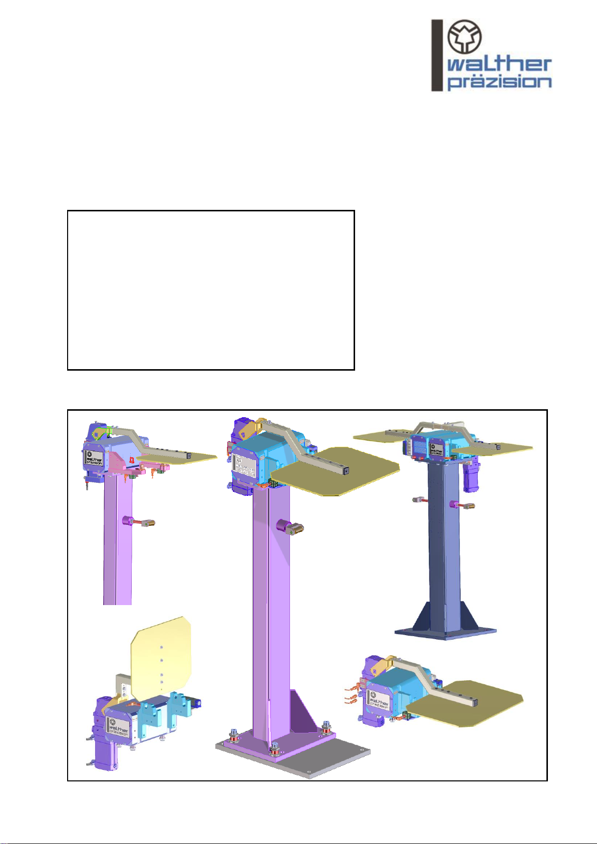
2 Installation manual
2.1 General
The tool parking station station has to be assembled, while taking into account the general accident prevention
guidelines, so that:
- a perfect operation is guaranteed.
- it is ensured that all single components and all mobile parts are without damage.
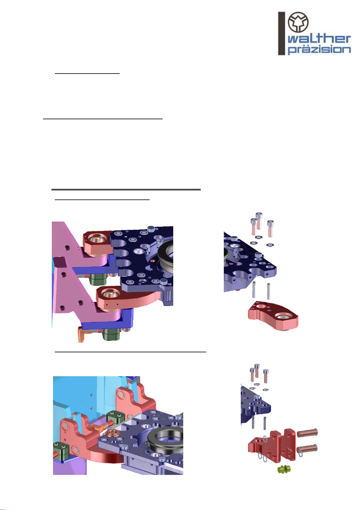
To avoid damage when dropping and picking up the tool side, as well as to prevent life-threatening injuries during
installation of the parking station, the following points must be observed:
- The installation works –mounting and installation of the tool parking station –may only be carried out
by qualified persons under consideration of the safety instructions.
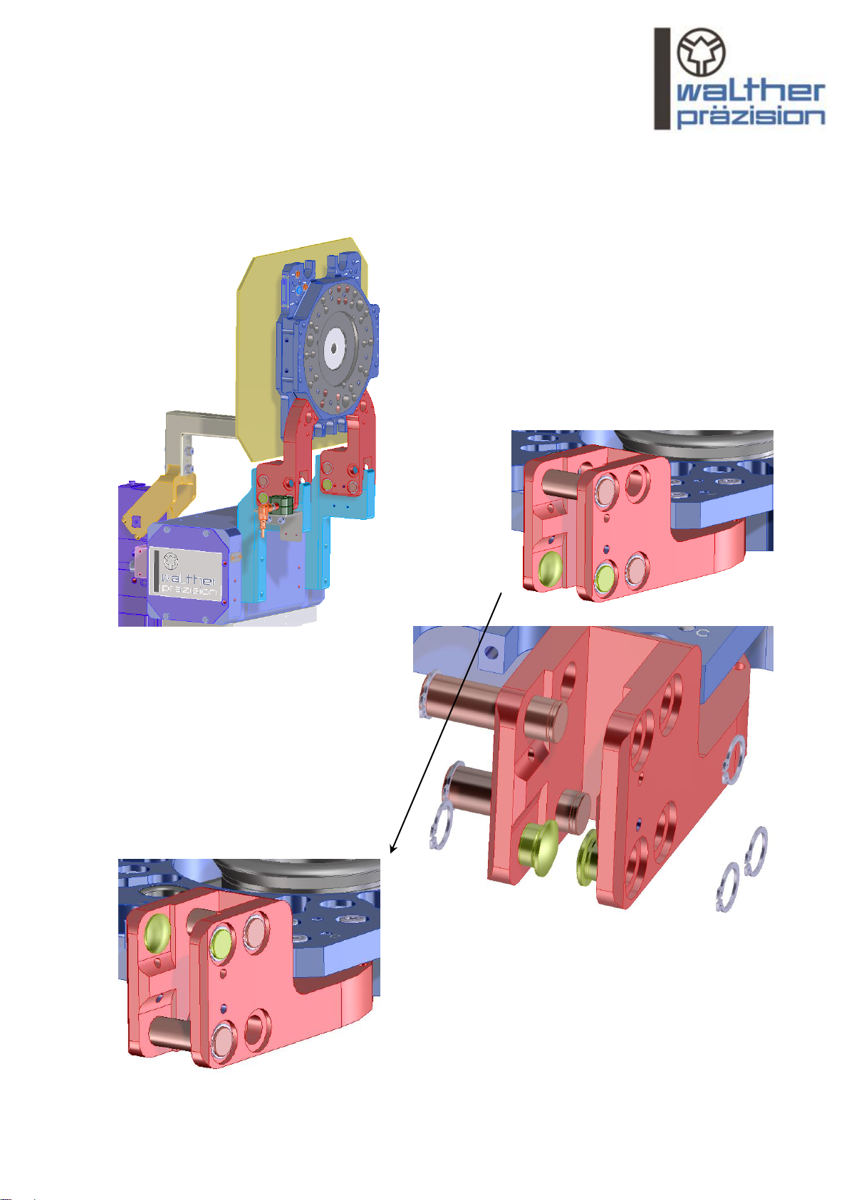
- Before beginning of the installation works all components of the tool changing system must be checked for
transport damage.
- Check whether all screw connections are correctly and properly tightened.
- Any occurring radial stresses caused by long and heavy connection hoses must be absorbed by suitable
supporting devices.

3
2.2 Preparing for installation
The correct position of the tool parking station must be established before the tool parking station is
removed from the packaging. The following information is therefore included on the packaging produced by
WALTHER-PRÄZISION:
- Drawing number
- Ident number
The following points should be observed:
- The tool parking stations must not be parked without being secured against tipping over. Due to its great height,
it may tip over under even the slightest collision.
- No tool sides should be stored in a tool parking station that is not properly affixed to its location.
- No tool sides must be stored in the tool parking station if no torque support is available.
If this is not observed, serious consequential damages may be the result.
WALTHER-PRÄZISION assumes no guarantee and accepts no liability in
these cases and all other cases of negligent acts resulting in damage or
injury.
3 Parking types and the associated parking arms
3.1 Horizontal parking 95816 (bolt-bush)
Parking arms:
Bearing for MM1 (right) 1-91489-B-00004-36-Z02 ident no 67972
Bearing for MM1 (left) 1-91489-B-00005-36-Z02 ident no 67973
3.2 Horizontal parking 95813 / 95817 (bar guide, bearing bolts)
- Parking arms:
Bearing right (WS) 1-91489-B-00009-36-Y10 ident no 75132
Bearing left (WS) 1-91489-B-00010-36-Y10 ident no 75133

4
- Parking arms:
Bearing left horizontal / vertical (WS) 1-91489-B-00126-36-Y10 ident no 127188
Bearing right horizontal / vertical (WS) 1-91489-B-00127-36-Y10 ident no 127189
The bearing bolts on the parking arms must be in the standard assembly variant shown
(corresponds to the delivery state)
3.3 Vertical parking 95815 / 95818 standard assembly variant (rear parking)
Parking arms:
Bearing left horizontal / vertical (WS) 1-91489-B-00126-36-Y10 ident no 127188
Bearing right horizontal / vertical (WS) 1-91489-B-00127-36-Y10 ident no 127189
- Standard assembly variant / rear parking.

5
- Special assembly variant for packing the tool in front of the parking station
The bearing bolts of the parking station should be used in the special assembly variant shown below
(does not correspond to the delivery state).
Standard assembly variant
By removing the retaining ring, it is possible
to convert the bearing bolts and limiting bolts to
a special assembly variant for parking the tool
side in front of the parking station.
Reinsert the bearing bolts and limiting bolts and
fix into position using the retaining rings.
Special assembly variants

6
4 Securing, aligning, and adjusting tool parking stations.
The pictures in this brief guide show examples of parking arms. These pictures are not always the same
as the order. Description of the process is essential and applies to all different parking arms.
4.1 Tool parking stations without frame
There are various tool parking stations without a frame, and they should be affixed to a stated customer structure.
Examples of this are:
parking head for affixing to a parking arms for affixing parking arms for affixing
customer structure on the ground on the wall
As a first step, the parking head or the parking arms should be attached to the stated customer structure in an appropriate
manner. It should be taken into account that the tool parking station should be affixed such that it is horizontal
in all directions. Determining the location of the tool parking station is carried out with a precision spirit level
(see section “Aligning the tool parking station vertically”). At the point in time where the result is unsatisfactory
then any inaccuracies in the customer structure should be professionally rectified, or shims should be positioned
underneath. Balancing the substructure and monitoring the vertical position of the tool parking station with a
precision spirit level occurs as often as is necessary until the tool parking station is vertical.
The last step is always to check the horizontal position of the placement head with a precision spirit level.
4.2 Tool parking station with frame and without level setting
In the first step, the frame should be affixed to the stated customer structure
in an appropriate manner. It should be borne in mind that the frame should be
affixed such that it is vertically aligned. Determining the location of the frame
is carried out with a precision spirit level
(see section “Aligning the tool parking station vertically”).
At the point in time where the result is unsatisfactory
then any inaccuracies in the customer structure should be professionally rectified, or
shims should be positioned underneath. Balancing the substructure and
monitoring the vertical position of the took parking station with a
precision spirit level occurs as often as is necessary until the
tool parking station is vertical. The last step is always to check the horizontal position of
the placement head with a precision spirit level.
The frame can then either be anchored in the hall floor in a suitable manner
or a steel anchored bottom plate can be
welded on instead.
The tool parking station can now be removed from the crane.
4.3 Tool parking station with frame and level setting
The level setting means that alignment becomes
much simpler if the customer structure has inaccuracies.
The base plate of the level setting can be directly
set up in the position provided. It should be affixed to the
hall floor in an appropriate manner:
The tool parking station is then set up and aligned
as in the section “Description in line with images”

7
4.4 Drill pictures for level settings

8
4.5 Description in line with images
4.5.1 Step 1: Affix tool parking station with level setting to the customer structure
Position the various tool
parking stations (horizontal, vertical)
in the appropriate locations,
but do not release the tool parking
station from the crane, and mark out
the 4 attachment points on the
ground.
Establish attachment points and use
customer-specific anchors (an example
of such an anchor is shown).
Secure the tool parking station
with customer-specific
fastening screws
Caution:
The mounting plate must not be
able to move after attachment,
which is the only way to ensure that
the tool parking station is securely fixed
into position
Mounting plate of level setting

9
4.5.2 Step 2: Aligning the tool parking station vertically
As shown in the following pictures, determine the status of the tool parking station with a precision spirit level
in both X-direction and Y-direction (horizontal and vertical).
horizontal tool parking station
X- direction Y- direction
vertical tool parking station
X- direction Y- direction

10
Groove nuts
By adjusting the 4 setting screws with a SW36 spanner, the tool parking station is now aligned vertically.
Adjusting the 4 setting screws and monitoring the vertical position of the tool parking station with a
precision spirit level occurs as often as is necessary until the tool parking station is vertical
The tool parking station can now be removed from the crane.
Secure setting screws with the groove nuts
(with hook wrench, secured with Schnorr - lock washers).
Always check the vertical position of the tool parking station with a precision spirit level as the last step.
4.5.3 Step 3: Use levelling bush (lift the floating position)
The floating position is lifted by replacing two (diagonal) spacer bushes with the two supplied
levelling bushes.
supplied
levelling bushes
unscrewed
spacer bushes
unscrew
spacer bushes

11
Replace spacer bush
for a levelling bush
Insert screw with replaced
levelling bushes into the locations
where the screws with
the spacer bushes (diagonal)
were removed earlier.
This applies to horizontal and
vertical parking stations.
Do not lose
the spacer bush

12
4.5.4 Step 4: Align tool side to the tool parking station
- horizontal
Insert the tool side with attached tool (not illustrated here) into the parking station.
The tool side of the tool changer is now
aligned in Y-direction to the parking head
that was aligned earlier.
This must occur with an attached tool,
which is not illustrated here
To do so, a ruler is placed flush on
the parking head, and the distance
between the surface of the plate and the
upper edge of the ruler in the front and
rear section is measured using depth
callipers.
Both dimensions must be identical.
Important:
The ruler must lie flush on the parking
head, and must not tip over to the front
or the back.

13
CAUTION!
No tool sides must be stored in the tool parking station
if no torque support is available.
If this is not observed, serious consequential
damages may be the result.
All suitable types of torque support are permitted.
The torque support is mounted on site by the customer
then adjusted to the construction.
It must be ensured that no torque is affecting the
parking arms of the tool side.
WALTHER-PRÄZISION assumes no guarantee
and accepts no liability in cases of negligent
acts resulting in damage or injury.
Adjusting the torque supports as well as monitoring and measuring the optimal position of the
tool takes place as often as required until the optimal position of the tool is achieved.
Always measure out and check the optimal position of the tool as a final step.
More than one torque support is used in the
case of highly asymmetric tools.
This torque support is affixed outside the
parking station in the area around the
customer structure.
Measurements should take place as shown
in the image so that the tool is also
aligned in x-direction.
Aligning is carried out when the different
torque supports are adjusted accordingly.
If the measurement is not identical at both
measurement points, then the tool side must
be realigned once again with the aid
of torque supports.
The torque supports are adjusted in length until
the measurement is identical at both
measurement points.
All information regarding the different torque
supports are described in the
point “Torque Support”.
Torque support

14
- vertical
The tool side of the tool changer
is now aligned on the previously aligned
parking head.
This must occur with an attached tool, which
is not illustrated here.
To do so, a triangle is placed flush on the parking head and the perpendicularity to the tool side is determined.
In case that both edges of the locking ring are not in contact with the vertical edge of the triangle, then
the tool side must be realigned with the aid of the torque support.
The torque support is adjusted in terms of length such that the ruler touches both edges of the locking ring equally.
All information regarding the different torque supports is described under “Torque support”.
Insert the tool side with
attached tool
(not illustrated here)
into the parking station
Perpendicularity is present if
both edges of the locking ring
touch the vertical edge of the
triangle.
Important:
The ruler must lie flush on the
parking head and must not lift
up on one side.
Torque support

15
More than one torque support is used in the case of highly asymmetric tools.
This torque support is affixed outside the parking station in the area around the customer structure.
In order for the tool to be aligned across the parking station, the horizontal alignment of the
tool side should also be checked and adjusted (similar to the horizontal parking station).
Aligning is carried out when the different torque supports are adjusted accordingly.
Adjusting the torque supports as well as monitoring and measuring the optimal position of the
tool takes place as often as required until the optimal position of the tool is achieved.
Always measure out and check the optimal position of the tool as a final step.
4.5.5 Step 5: Insert spacer bushes (recreate floating bearing)
At the end it is absolutely imperative
that the 2 levelling bushes are
replaced by the 2 spacer bushes.
This is important as the floating
bearing is available once more,
meaning that parking the tool
sides into the parking station
can correctly take place
once again.
This applies for the horizontal and
vertical parking station.
Do not lose the
levelling bushes.
Remove screws from
both levelling bushes
Attach screws
with both spacer bushes

16
4.6 Summary of correct and incorrect alignment:
INCORRECT
CORRECT
CORRECT
INCORRECT
INCORRECT
INCORRECT
CORRECT
INCORRECT
FALSCH
INCORRECT
LSCH
FP-side
Tool
= 90°
<90°
>90°
FP-side
FP-side
FP-side
FP-side
>90°
= 90°
<90°
Tool
Tool
Tool
FP-side
Tool
FP-side
Tool
Tool
Tool
FP-side
FP-side
Tool
= 90°
<90°
>90°

17
5 Torque support
It should be ensured that there is no torque acting on the parking arms on the side of the tool.
WALTHER-PRÄZISION provides several types of torque support for this purpose:
Example of welded design:
CAUTION!
No tool sides must be stored in the tool
parking station if no torque support
is available.
If this is not observed, serious consequential
damages may be the result.
All suitable types of torque
support are permitted.
The torque support is mounted by the customer
on site and then adapted to the construction
(observe clearance of 50 mm, see drawing).
WALTHER-PRÄZISION assumes no guarantee
and accepts no liability in cases of negligent acts
resulting in damage or injury.
General:
The torque support should be affixed at a suitable location depending on the type of parking arm (pin bushing, bolt-bar
guide) and also on the type of tool parking (horizontal, vertical).
- To do so, the customer determines the position, depending on the structure, where the torque support supports the tool
such that the coupling plane of the tool side of the changing system is aligned vertically or horizontally.
Maintenance:
- Correct function of the torque support should be frequently monitored and, if necessary, restored by e.g. replacing a
worn roller.
The procedure for the various kinds of parking is illustrated using the following examples:
Standard, roller
can be amended
by the customer
Standard, bolt and bush
Part of the
customer structure of the tool

18
a
b
a
a
b
5.1 Vertical parking
Affixing the torque support should be done such that the coupling plane of the tool side of the changing system
creates a vertical plane. Vertical parking can take place in both directions.
- Use a precision spirit level to check whether the milled edge of the parking head is horizontally aligned.
If this is not the case then the frame must be aligned vertically as described in “Securing, aligning,
and adjusting tool parking stations”.
- Determine the necessary mounting dimensions (measurements a and b in example) for the torque support.
(Dependent on the customer structure of the tool and direction of parking).
- If necessary, professionally remove the surface coating for a suitable welding process.
- Affix the selected torque support to the determined position, e.g. through welding.
- Ensure vertical alignment of the coupling plane. The length of the threaded bolt (measurement b)
can be amended for fine adjustments.
See “Securing, aligning, and adjusting tool
parking stations based on images”
- Ensure the final position of the torque support by tightening
the hexagon nut.
- Check the vertical alignment of the coupling plane, e.g.
with a back square
(see “Aligning the tool parking station vertically”).
5.2 Horizontal parking
Affixing the torque support should be done such that the
coupling plane of the tool side of the changing system creates a horizontal plane:
- Use a precision spirit level to check whether the milled edge of the parking head is
horizontally aligned. If this is not the case then the frame must be aligned vertically
as described in “Securing, aligning, and adjusting tool parking stations”.
- Determine the necessary mounting dimensions (measurements a and b in example) for
the torque support. (Dependent on the customer structure of the tool).
- If necessary, professionally remove the surface coating for a
suitable welding process.
- Affix the selected torque support to the determined position e.g. through welding.
- Ensure horizontal alignment of the coupling plane. The length of the threaded bolt
(measurement b) can be amended for fine adjustments. See “Securing, aligning,
and adjusting tool parking stations based on images”
- Ensure the final position of the torque support by tightening the hexagon nut.
- Check the vertical alignment of the coupling plane, e.g. with a back square
(see “Aligning the tool parking station vertically”).
a
b
Roller
Bolt and
bush
Roller
Rolle
Examples:

19
6 Adjusting the opening angle of the flap cover
For horizontal parking stations and for vertical parking stations, we use a vario clamp of 0-135°. The adjustment of the
opening angle depends on the scope of delivery.
Example for infinity variable adjustment of the opening angle between 0° and 135° of flap covers for horizontal parking
stations:
Example for infinity variable adjustment of the opening angle between 0° and 135° of flap covers for vertical parking stations:
min. 0°
max. 135°
min. 0°
max. 135°

20
To adjust the opening angle, open the clamp first.
(The sensor for the electronic query of the opening angle displays the „open“ position.)
For safety reasons, the clamp can now be separated from the power supply.
Remove the protection plate at the bottom of the clamp.
Adjust the desired opening angle with a hexagon wrench (5mm) via the adjustment screw.
ATTENTION
During adjustment and operation, keep a safe distance to the movable parts (risk of crushing!)
By rotating the adjustment screw clockwise, the opening angle is enlarged. For diminishing the opening angle, rotate the
adjusting screw counter clockwise. Make sure that the opening angle is never placed below the 0° position.
7 Inspect
1. Is the parking head horizontally or vertically aligned?
Use a precision spirit level to check whether the milled edge of the parking head is aligned in
both directions, horizontally and vertically.
If not, check the fixture. Are the anchors, e.g. in the ground, the setting screws on the levelling plate,
and all other screw connections still secure?
2. Is the coupling plane of the tool side vertically or horizontally aligned?
Check the position of the torque support for correct, secure seating.
Check the roller on the torque support for wear and tear, and replace if necessary.
hexagon wrench
sensor
sensor
This manual suits for next models
5
Table of contents
Popular Automobile Electronic manuals by other brands

Hawk
Hawk HRA-6000 V5 Series User & installation manual

VBOX Motorsport
VBOX Motorsport VBOX HD Hardware manual

Velleman
Velleman SPBS10 user manual

Valeo
Valeo Light/on&off instruction manual

Ecco
Ecco Smartspot EC1011 Installation and operation instructions

Audiovox
Audiovox Auto Security AS-GMDLT03 installation guide