manuals.online logo
Brands
  1. Home
  2. •
  3. Brands
  4. •
  5. Mercedes-Benz
  6. •
  7. Automobile Electronic
  8. •
  9. Mercedes-Benz 163.154 Operating and installation instructions

Mercedes-Benz 163.154 Operating and installation instructions

This manual suits for next models

2

Other Mercedes-Benz Automobile Electronic manuals

Mercedes-Benz Car receiver User manual

Mercedes-Benz

Mercedes-Benz Car receiver User manual

Mercedes-Benz Nav+4 User manual

Mercedes-Benz

Mercedes-Benz Nav+4 User manual

Mercedes-Benz Audio 10 User manual

Mercedes-Benz

Mercedes-Benz Audio 10 User manual

Mercedes-Benz COMAND User manual

Mercedes-Benz

Mercedes-Benz COMAND User manual

Mercedes-Benz MVI250 User manual

Mercedes-Benz

Mercedes-Benz MVI250 User manual

Mercedes-Benz Car receiver User manual

Mercedes-Benz

Mercedes-Benz Car receiver User manual

Popular Automobile Electronic manuals by other brands

DRG LC 120 installation instructions

DRG

DRG LC 120 installation instructions

Blue Ox BX8848 installation instructions

Blue Ox

Blue Ox BX8848 installation instructions

Dometic MAGICWATCH MWE890K Installation and operating manual

Dometic

Dometic MAGICWATCH MWE890K Installation and operating manual

Honeywell Thor VM3A user guide

Honeywell

Honeywell Thor VM3A user guide

Waeco MagicWatch MWE250 Installation and operating manual

Waeco

Waeco MagicWatch MWE250 Installation and operating manual

GoldCruise GC90Ci installation manual

GoldCruise

GoldCruise GC90Ci installation manual

Rydeen BKM091 user manual

Rydeen

Rydeen BKM091 user manual

Skoda 5E0 054 630 Fitting instructions

Skoda

Skoda 5E0 054 630 Fitting instructions

VDO SENDER UNIT 2159-0 datasheet

VDO

VDO SENDER UNIT 2159-0 datasheet

iDataLink maestro Rr install guide

iDataLink

iDataLink maestro Rr install guide

Audiovox PRO-PDA15 installation guide

Audiovox

Audiovox PRO-PDA15 installation guide

Movon MDAS-3LFFHD user manual

Movon

Movon MDAS-3LFFHD user manual

Pioneer Comfort adapter CA-D-PI.150 quick start guide

Pioneer

Pioneer Comfort adapter CA-D-PI.150 quick start guide

Dietz 1110 instruction manual

Dietz

Dietz 1110 instruction manual

Perfect Power SMT8-T5 Technical manual

Perfect Power

Perfect Power SMT8-T5 Technical manual

Crux RVCFD-79 manual

Crux

Crux RVCFD-79 manual

Nonda ZUS user manual

Nonda

Nonda ZUS user manual

Adaptiv Mini installation guide

Adaptiv

Adaptiv Mini installation guide

manuals.online logo
manuals.online logoBrands
  • About & Mission
  • Contact us
  • Privacy Policy
  • Terms and Conditions

Copyright 2025 Manuals.Online. All Rights Reserved.

This bulletin has been created and maintained in accordance with MBUSA-SLP 5.1, Document and Data Control, and
MBUSA-SLP 16.1, Control of Quality Records.
© 2000 Mercedes-Benz USA, Inc. All rights reserved. Reproduction or translation in whole
Mercedes-Benz Canada, Inc. or in part is not permitted without authorization from the
Technical Information publisher. Printed in the USA.
www.MBUSA.com 1-800-FOR-MERCedes



Date: May 2000
Order No.: T-SI-82.70/131
Supersedes:
Group: 82
SUBJECT: MODEL 163.154/172/174 (MY 2000)
CELLULAR TELEPHONE INSTALLATION
=
==
=WARNING!
Disconnecting the negative battery cable is not recommended due to otherwise extensive
reprogramming requirements. WIRING HARNESSES WILL BE ELECTRICALLY ACTIVE. IT IS
THEREFORE NECESSARY TO EXERCISE EXTREME CAUTION WHILE EXECUTING THESE
INSTALLATION INSTRUCTIONS. FAILURE TO DO SO, COULD RESULT IN SEVERE PERSONAL
INJURY OR DEATH FROM ELECTRICAL SHOCK. The ignition and radio power must remain OFF
until the final test is performed.
Application specific D2B notes:
•Only the accessory telephone requires the use of D2B fiber optics.
•The Mercedes-Benz accessory CD changer maintains the use of electrical wiring and is NOT on the D2B
ring.
•The vehicle is configured at the factory without D2B fiber cabling.
•All fibers required for telephone installation are included in the telephone installation kit.
A. Installation preparation – all configurations
1. Read this bulletin in its entirety.
2. Unpack and compare the installation kit(s) contents against the Parts Information list on page 12 of
this bulletin.
3. Separate the operating guides and client accessories (i.e. chargers, cassette tapes, CDs, etc.) and
place them in the glove box or appropriate storage compartment.
4. Remove the MCS (radio) control unit from the center dash and disconnect all cable connections.
Note: Refer to S-SI-82.64/123, D2B Fiber Optic Configuration and Version Coding for proper D2B
fiber handling instructions.
T-SI-82.70/131 nMay 2000
2
B. Installing the linear compensator
1. Remove the climate control module, glove
box insert, and passenger side lower dash
panel (Figure 1).
Figure 1 P82.70-2941-01
2. Secure the linear compensator to the
mounting plate with three M4 nuts (Figure 2).
Figure 2 P82.70-2942-01
T-SI-86.70/131 n May 2000 3
3. Temporarily move the main harness, running
vertically along the right center dash support,
from the mounting-clamp or wire-tie by
accessing it from the glove box side and:
(Figure 3 –before) (Figure 4 –after)
a. gently widening the clamp and sliding
the harness out
or
b. carefully cutting away the wire-tie
Figure 3 P82.70-2943-01
Figure 4 P82.70-2944-01
T-SI-82.70/131 nMay 2000
4
4. Loosen the lower most 10-mm bolt securing
the right center dash support to the dash
frame just enough to slide the compensator
bracket foot between the bolt head and
support bracket (A, Figure 6).
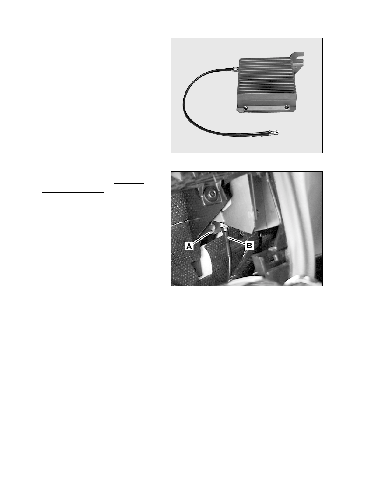
5. Connect the 375-mm (15-in.) antenna
extension to the compensator connection
labeled ANTENNA (Figure 5).
Note: The other cable end will not be
connected until near the end of the
installation. DO NOT reverse the coaxial
connections in steps 5 and 7.
6. Install the completed compensator assembly
behind the dash, down and to the right of the
radio mounting area (Figure 6).
Note: Install the assembly through the
climate control opening and then orient it into
position. The booster is oriented in the
vertical plane with the green 14-pole
connector facing down. Be sure that the two
padded mounting-ears hang properly over the
dash support bracket and that the lower
slotted leg fits between the bolt loosened in
step 4 and the dash support bracket. Secure
the assembly by tightening the 10-mm bolt
loosened in step 4.
7. Connect the RF cable coming from the center
console to the compensator RF jack and
tighten it firmly by hand (B, Figure 6).
Note: This will be the connector labeled
PORTABLE, although it cannot be read once
installed, and facing down after compensator
installation is completed.
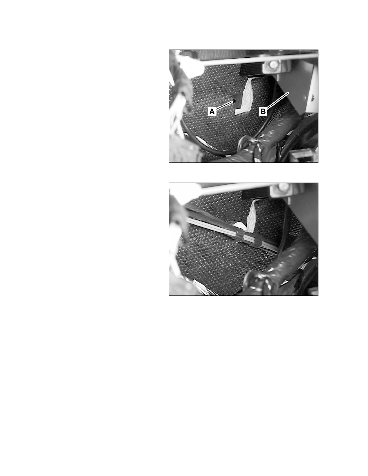
8. Use the supplied wire-tie to again secure the
main harness to the dash support separated
in step 3.
Figure 5 P82.70-2945-01
Figure 6 P82.70-2946-01
T-SI-86.70/131 n May 2000 5
C. Installing the portable support electronics (PSE) module
1. Place the template on the inside of the right
lower dash panel (Figure 7).
Note: Be sure that the back and right edges
of the template are flush with the plastic
panel, NOT the foam.
Figure 7 P82.70-2947-01
2. Follow the instructions on the template for
marking and removing the foam and
subsequent drilling of the PSE mounting
holes (Figure 8).
Note: Remove the foam by cutting it with a
sharp razor knife, lifting up a corner of the
adhesive film on the back and then peeling it
away in one piece. DO NOT grasp by the
foam as it will tear and leave the adhesive
behind.
Figure 8 P82.70-2948-01
3. Mount the PSE module to the bottom of the
under-dash panel with four M4 x 6 machine
screws.
Note: The 25-pole D-connector should face
toward the front of the vehicle.
4. Connect the 25-pole D-connector and D2B
fiber to the PSE. (Route the cable as shown
in Figure 9 and be sure to slide the cable-clip
over the front edge of the lower dash panel
as shown.
Note: Be sure that the portion of the cable
routed under the auxiliary power outlet is not
under stress that would cause it to abrade
against the outlet when installing the clip. Figure 9 P82.70-2949
T-SI-82.70/131 nMay 2000
6
5. Reinstall the lower dash panel making sure
that the cables routing into the radio
compartment are not stressed and are
unobstructed.
6. Locate the cable-clip retaining hole (A, Figure
10) just below and to the left of the linear
compensator (B, Figure 10).
Figure 10 P82.70-2950-01
7. Route the telephone cable harness to this
point and press the cable-clip (already
attached to the harness) into the retaining
hole (Figure 11).
Figure 11 P82.70-2951-01
D. Making electrical connections
1. Connect the 14-pole green connector from the telephone harness to the connector at the bottom of the
linear compensator.
2. Connect the 3-pole black power connector from the telephone harness to the mating connector on the
vehicle radio harness.
3. Connect the 2-pole green microphone connector from the telephone harness to the mating connector on
the vehicle radio harness.
4. Connect the male RJ-45 connector from the vehicle radio harness to the mating connnector on the PSE
harness.
T-SI-86.70/131 n May 2000 7
E. Installing the handset
1. Remove the center console storage box and
locate the coaxial cable/RJ-45 data cable
assembly under the box.
2. Place the template on the storage box
(Figure 12).
3. Drill one 19-mm (3/4-in.) hole and five 4.5-
mm (3/16-in.) holes in the storage box where
indicated on the template.
Figure 12 P82.70-2952-01
4. Route the coil-cord through the 19-mm
opening and secure the coil-cord strain relief
to the storage box using the 4.5-mm strain
relief hole and an M4 x 14 screw with M4
acorn nut (Figure 13).
Figure 13 P82.70-2953-01
5. Mount the cradle to the storage box with four
M4 x 8 screws (Figure 14).
Note: The cradle release buttons should be
pointing toward the bottom of the box.
6. Connect the RJ-45 and mini-UHF connectors
from the coil-cord to the mating vehicle
connectors in the center console.
7. Reinstall the storage box.
8. Attach the handset battery, connect the coil-
cord, and place the telephone into the cradle
(Figure 14).
9. The connection point of the antenna lead
installed in step B5 will depend on the level of
T-SI-82.70/131 nMay 2000
8
other equipment installed in the vehicle. Figure 14 P82.70-295401
Proceed to:
•Section F if the vehicle is navigation equipped.
•Section G if the vehicle is not navigation equipped.
F. Connection of the linear compensator to the antenna in navigation equipped vehicles
Note: Navigation system equipped vehicles
are identified by the integrated GPS/cellular
antenna on the roof characterized by the
large flat portion adjacent to the roof panel
(Figure 15).
Figure 15 P82.70-2955-01
1. Locate the antenna splitter clipped to the
dash support bracket on the left side of the
MCS compartment opening (Figure 16).
Figure 16 P82.70-2956-01
T-SI-86.70/131 n May 2000 9
2. Lift the splitter off the dash support bracket
and connect the RF cable from the linear
compensator (step B5) to the telephone
output on the splitter (the left jack if reading
the text on the splitter). Hand-tighten the
connections and then gently snug them up
with a wrench (Figure 17).
3. Place the antenna splitter assembly back into
position.
4. Skip to Section H.
Figure 17 P82.70-2957-01
G. Non-navigation equipped vehicles
Note: Non-navigation system equipped
vehicles are identified by a plug in the place
of a roof antenna.
1. Locate the antenna coming from the main
vehicle harness.
2. Use the double female SAP coupler from the
telephone kit to connect the antenna cable to
the cable coming from the linear
compensator (step B5). Hand-tighten the
coupler and then snug it up 1/8-1/4-turn with
a wrench (Figure 18).
Figure 18 P82.70-2958-01
3. Use a screwdriver to remove the cover (1)
from the antenna base located near the back
of the roof edge (Figure 19).
Figure 19 P82.70-2276-1
T-SI-82.70/131 nMay 2000
10
4. Place the contoured spacer (2) slanting
backwards onto the grommet (6) in the roof
(Figure 20).
5. Screw the hex-nut (3) up to the bolt collar (4)
and insert the bolt through the contoured
spacer (Figure 20).
6. Screw and hand-tighten the bolt into the
factory-installed base.
7. Tighten, making sure not to over-tighten, the
hex-nut (3) onto the contoured spacer
(Figure 20).
8. Place the top cap (5) over the whip and allow
the inner portion of the cap to fit into the
contoured spacer grove. Press firmly down
on the cap until it snaps into place (Figure
20).
Figure 20 P82.70-2277-01
H. Final assembly and function test
1. Reinstall the climate control module and MCS (radio) unit.
2. Program the telephone per S-SI-82.70/124, StarTAC Portable Telephone Programming.
3. Verify proper telephone operation per the following checklist:
GHandset dialing is functioning
GHead unit dialing is functioning
GHandset incoming/outgoing call audio is clear
GHands-free incoming/outgoing call audio is clear
GAutomatic memory download is functioning (In order for this feature to operate, it may be
necessary to store a test number in the telephone handset; stored numbers should be available
for dialing from the head unit after automatic download.)