W&T 57753 User manual

SIP Ring Switch
valid for:
#57753 SIP Ring Switch 4xOut
Release 1.68 September 2023
Manual
Installation, Startup and Application

© 10/2021 by Wiesemann und Theis GmbH
Microsoft, MS-DOS, Windows, Winsock and Visual Basic
are registered trademarks of the Microsoft Corporation.
Subject to error and alteration:
Since it is posssible that we make mistakes, you mustn’t use any of our statements
without verication. Please, inform us of any error or misunderstanding you come
about, so we can identify and eliminate it as soon as possible.
Carry out your work on or with W&T products only to the extent that they are descri-
bed here and after you have completely read and understood the manual or guide.
We are not liable for unauthorized repairs or tampering. When in doubt, check rst
with us or with your dealer.

3
Conent
Content
1. Legal notices...................................................................... 5
Warning notice system ...................................................................................... 5
Qualied personnel ............................................................................................ 5
Disposal.............................................................................................................. 6
Symbols on the product ..................................................................................... 6
2. Safety notices .................................................................... 7
General notices .................................................................................................. 7
Intended use....................................................................................................... 7
Electrical safety.................................................................................................. 7
EMC 8
Batteries ............................................................................................................. 8
3. Quick Startup ................................................................... 10
Network connection......................................................................................... 10
Supply voltage.................................................................................................. 10
IP address assignment .................................................................................... 10
Function test .................................................................................................... 10
4. Product introduction ....................................................... 11
Hardware.......................................................................................................... 11
Network security .............................................................................................. 11
Application and access possibilities................................................................ 12
Actions ............................................................................................................. 13

4
Conent
5. Installation and wiring...................................................... 14
Montage #57753.............................................................................................. 14
Terminal assignment 57753 ........................................................................... 14
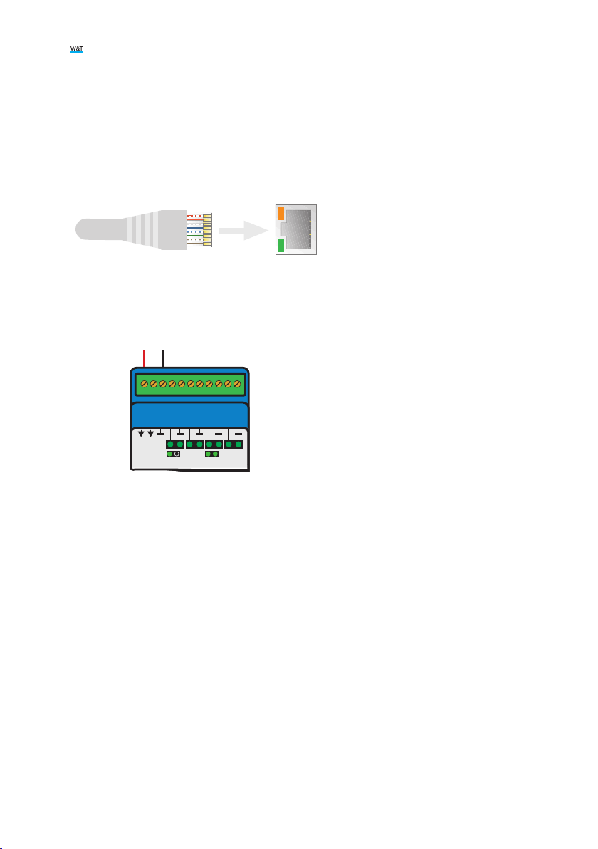
Wiring #57753.................................................................................................. 15
Network connection......................................................................................... 16
6. Initial start-up .................................................................. 17
Assigning the IP address ................................................................................. 17
Changing the set IP parameters ...................................................................... 18
7. Basic settings................................................................... 19
Conguring the Outputs................................................................................... 19
Date / Time....................................................................................................... 19
Language / Info ................................................................................................ 20
Password ......................................................................................................... 20
Certicates....................................................................................................... 21
8. Basic applications............................................................ 22
SIP - Dialing via IP telephony............................................................................ 22
Browser access ............................................................................................... 24
Sending email................................................................................................... 26
9. Actions ............................................................................. 28
Trigger .............................................................................................................. 28
Actions ............................................................................................................. 30
10. Access from own applications ...................................... 33
Command strings ASCII................................................................................... 33
HTTP request ................................................................................................... 34
11. Appendix ........................................................................ 35
Alternatives for IP address assignment .......................................................... 35
Firmware update .............................................................................................. 36
Emergency access ........................................................................................... 36
12. Technical data................................................................ 37

5
Legal notices
1. Legal notices
Warning notice system
This manual contains notices that must be observed for your personal safety as
well as to prevent damage to equipment. The notices are emphasized using a war-
ning sign. Depending on the hazard level the warning notices are shown in decrea-
sing severity as follows.
1DANGER
Indicates a hazard which results in death or severe injury if no appropriate preventi-
ve actions are taken.
1WARNING
Indicates a hazard which can result in death or severe injury if no appropriate pre-
ventive actions are taken.
1CAUTION
Indicates a hazard that can result in slight injury if no appropriate preventive
actions are taken.
1NOTE
Indicates a hazard which can result in equipment damage if no appropriate preven-
tive actions are taken.
If more than one hazard level pertains, the highest level of warning is always used.
If the warning sign is used in a warning notice to warn of personal injury, the same
warning notice may have an additional warning of equipment damage appended.
Qualied personnel
The product described in this manual may be installed and placed in operation only
by personnel who are qualied for the respective task.
The documentation associated with the respective task must be followed, especial-

6
Legal notices
ly the safety and warning notices contained therein.
Qualied personnel are dened as those who are qualied by their training and
experience to recognize risks when handling the described products and to avoid
possible hazards.
Disposal
Electronic equipment may not be disposed of with normal waste, but rather must be
brought to a proper electrical scrap processing facility.
Symbols on the product
Symbol Explanation
CE Mark
The product conforms to the requirements of the relevant EU
Directives.
UKCA marking
The product complies with the requirements of the United
Kingdom (GB)
WEEE Mark
The product may not be disposed of with normal waste, but
rather in accordance with local disposal regulations for elec-
trical scrap.

7
Safety notices
2. Safety notices
General notices
This manual is intended for the installer of the SIP Ring Switch described in the ma-
nual and must be read and understood before starting work. The devices are to be
installed and put in operation only by qualied personnel.
Intended use
1DANGER
The SIP Ring Switch manufactured by Wiesemann & Theis are network remote swit-
ches with integrated web server and digital in- and outputs. They are used as a re-
mote switching and monitoring unit, accessible via TCP/IP-Ethernet using various
web and network protocols in accordance with the present manual.
Non-intended use is any other use or any modication to the described devices.
Electrical safety
1WARNING
Before beginning any kind of work on the SIP Ring Switch you must completely dis-
connect it from power. Be sure that the device cannot be inadvertently turned on
again!
The SIP Ring Switch may be used only in enclosed and dry rooms.
The device should not be subjected to high ambient temperatures or direct sunlight,
and it should be kept away from heat sources. Please observe the limits with res-
pect to maximum ambient temperature.
Ventilation openings must be clear of any obstacles. A distance of 10-15 cm be-
tween the SIP Ring Switch and nearby heat sources must be maintained.
Input voltage and output currents must not exceed the rated values in the specica-
tion.

8
Safety notices
When installing be sure that no stray wires stick out through the ventilation slit of
the SIP Ring Switch into the housing. Ensure that no individual wires stand off from
leads, that the lead is fully contained in the clamp and that the screws are tightly
fastened. Fully tighten screws on unused terminals.
The power supply used for the SIP Ring Switch must absolutely ensure safe
isolation of the low-voltage side from the supply mains according to EN60950-1 and
must have “LPS“ designation.
EMC
1NOTE
Only shielded network cables may be used for connecting the SIP Ring Switch to the
network.
In this case the SIP Ring Switch meet the noise immunity limits for industrial
applications and the stricter emissions limits for households and small businesses.
Therefore there are no EMC-related limitations with respect to the usability of the
devices in such environments.
The complete Declarations of Conformity for the devices described in the manual can
be found on the corresponding Internet page at the W&T homepage: http://www.wut.
de.
Batteries
The SIP Ring Switch contains a 3V lithium-manganese dioxide button battery type
CR1632 for backing up the internal clock. This battery has an expected lifetime of
10 years and must be replaced only by a battery of the same type.
When using the SIP Ring Switch in a network environment with access to a time
server, the battery is not essential for correct function of the device and can be
removed.
1CAUTION
The battery may be removed or replaced by an electrotechnical specialist, only.
To remove the battery, open the housing as follows:

9
Safety notices
#57753
Rasthaken
Batterie
Use a pointed object to press on the latching hooks on the side of the housing and
at the same time pull the bottom of the housing out of the top shell.
Then remove the stack of PCBs downwards from the housing.
The buffer battery for the clock module is located in a holder on the upper PCB.
After removing/replacing the battery, reassemble in reverse order.
Batteries and rechargeables must not be disposed of with normal waste, recycling
of used batteries and rechargeables is required by law. Used batteries may contain
harmful substances which can damage the environment or your health if not
disposed of properly.
Batteries also contain important raw materials such iron, zinc, manganese or nickel
and are recycled.

10
Quick Startup
3. Quick Startup
Network connection
1 2 3456 7 8
RJ45
Supply voltage
#57753
+ -
0
+ - + - + - + -
1 2 3
max. 4x500mA Out
+ -
12-48V
V
DD
Out
V
DD
IN
+
Inputs/Outputs
12 - 24V
Outputs: max. 4x500mA
VCC
01 2 3
12 - 24V DC
150mA +
Output Load
- - - -
-
+
Outp. =ON
Inp. =ON
+
For the rst test leave the outputs unwired.
IP address assignment
Install Wutility-Tool (Download: http://wut.de/wutility)
After starting Wutility your SIP Ring Switch appears in the device list. If multiple
devices are shown, please identify your device by the Mac address, that is printed
on a white sticker at the device: “EN = 00c0:3d......“ . If there is a DHCP server in your
network, you can use the assigned IP address for a rst test. Using the IP address
icon in WuTility you can assign a free static IP address instead to the SIP Ring
Switch.
Function test
Open the Web page of the SIP Ring Switch in a web browser using the address
http://<IP-address of the SIP Ring Switch>.

11
Product introduction
4. Product introduction
Hardware
#57753 - SIP Ring Switch 4xOut
Network interface: RJ45 10/100BaseT / PoE
Power: Screw terminal 12 … 24V DC
Outputs: 4 output channels
Output 12 ... 24V DC current driving max. 500mA
Network security
All available network services are congurable and must rst be enabled by the
administrator. By default only browser access, inventorying via Wutility, and the port
for initializing rmware updates are enabled. DHCP is also enabled.
You can explicitly specify for all communication paths whether the outputs may
be accessible. A list of the currently open TCP and UDP ports can be found in the
navigation tree under Port list.
Access rights
The SIP Ring Switch is congured and operated by using a web browser. There are
three authorization levels for access:
Guest
The guest has read-access to the status of outputs or counters without logging in.
User
A user can switch the outputs after logging in with a password if it is enabled for
access via the browser.

12
Product introduction
Administrator
After logging in with a password the administrator has unrestricted conguration
and access rights.
By default no passwords are assigned for the SIP Ring Switch. Simply click on the
Login button.
After login the navigation tree on the left side can be used to open the enabled con-
guration areas. For help and information about the respective conguration possi-
bilities click the Info buttons on the right side.
Clicking the Apply button makes the settings immediately effective.
For all other descriptions affecting the conguration, access with administrator login
is required.
Application and access possibilities
SIP
The core function of the SIP ring switch is to switch outputs by dialing extension
numbers in an IP PBX. The communication with the telephone system based on SIP
(Session Initiation Protocol).
Browser access
Using password protected access, you can also switch the outputs with the required
access rights.
Email sending
The SIP Ring Switch offers the option of sending email messages depending on
output states or at xed intervals. The SIP Ring Switch also supports authentication
procedures prescribed by public providers.
Web-API - HTTP requests / AJAX
The status of the outputs can be queried using HTTP requests. In addition the
outputs can be directly controlled using HTTP requests.

13
Product introduction
Individual applications
The SIP Ring Switch offers TCP socket access from your own applications.
The SIP Ring Switch supports addressing using command strings. With the support
of HTTP requests your own web applications (e.g. with PHP or JavaScript) can also
access the SIP Ring Switch.
Actions
Which output is to be switched to which state when a certain extension is called is
determined by creating corresponding actions.
In addition, actions can be created that are triggered by changes to the outputs or at
certain times, e.g. the sending of an e-mail message. Further actions are writing to a
le via FTP, sending data via TCP or an HTTP request, up to switching the outputs of
a SIP ring switch accessible via the network.

14
Installation and wiring
5. Installation and wiring
The described SIP Ring Switch may be installed and wired by qualied personnel
only. The generally applicable state of the art and corresponding prevailing
regulations and standards must be observed.
Montage #57753
The SIP Ring Switch 4xOut is intended for installation in the control cabinet or
sub-distribution. For mechanical xation, the SIP Ring Switch should be snapped
onto a 35mm top-hat rail according to DIN EN 50022. In doing so, the Web IO takes
up 45mm in width.
Terminal assignment 57753
Terminal Description / Function
1+ Vcc - Device supply 12-24V 150mA@24V
2+ Vcc - Device supply 12-24V 150mA@24V
3GND / Device supply
4Output 0 24V max. 500mA
5GND - Output 0
6Output 1 24V max. 500mA
7GND - Output 1
8Output 2 24V max. 500mA
9GND - Output 2
10 Output 3 24V max. 500mA
11 GND - Output 3

15
Installation and wiring
Wiring #57753
Connection of the supply voltage VDD
Connection of the supply voltageThe Web IO is supplied with a DC voltage between
12 and 24V.
1 8
SIP Ring Switch #57753
Digital, 4xOut
Power
Status
Error
Reset
Outputs: max. 4x500mA
Vcc
01 2 3
12 - 24V DC
150mA +
Output Load
Input/Output Mode Check
and LED Test shown on Reset
- - - -
-
+
Outp.
=
ON
Inp.
=
ON
+
URL: ______________
+-
12 - 24V
GND
With a typical industrial power supply of 24V, the SIP Ring Switch draws approxima-
tely 100mA of current.
1NOTE
IO channels that are congured as outputs are also supplied via VDD. The loads to
be switched must also be taken into account in the current consumption.

16
Installation and wiring
Output wiring
IO channels that are congured as outputs operate as current drivers and can be
loaded with max. 500mA each. The positive voltage applied to VDD .is switched to
the positive terminal of the IO channel, whereby the negative terminal is used as re-
ference ground.
Here is an example of the wiring of output 1.
+-
12 - 24V
GND
Last
Load
+ -
SIP Ring Switch #57753
Digital, 4xOut
Power
Status
Error
Reset
Outputs: max. 4x500mA
VCC
01 2 3
12 - 24V DC
150mA +
Output Load
Input/Output Mode Check
and LED Test shown on Reset
- - - -
-
+
Outp.
=
ON
Inp.
=
ON
+
URL: ______________
1 8
.
Network connection
A shielded standard ethernet patch cable (min. CAT5) with RJ45 plugs can be used
for the network connection.
12
3
4
5
678
RJ45
Link Speed
Tx+Tx-Rx+Rx-

17
Initial start-up
6. Initial start-up
After the SIP Ring Switch has been properly installed and wired, the power supply
can be switched on. All three status LEDs should light up briey. After approx. 5
seconds only the Power LED should remain on. The Status LED may ash.
If the network connection is working, the green LED in the network socket signals an
active link. The orange LED indicates the network speed:
On = 100MBit/s
Off = 10MBit/s
Assigning the IP address
At delivery, the SIP Ring Switch is set to IP address 0.0.0.0.0 and DHCP is activated.
Networks with DHCP
If a DHCP server is active in the network to which the SIP Ring Switch is connected,
an IP address should be automatically assigned to the SIP Ring Switch. To be able
to specically access the SIP Ring Switch, you should congure a reservation in
the DHCP server so that the SIP Ring Switch is always accessible under the same
address. The required Ethernet address can be found on the white sticker on the
device.
xxx
(If in doubt ask your network administrator)
Networks without DHCP
Install the WuTility program on a Windows PC (download from http://www.WuT.de).
If you do not have a Windows PC, read the subchapter Alternatives for IP address
assignment in the appendix.
When WuTility is started, the local subnet is scanned and all detected W&T network
components are listed. Select your SIP Ring Switch and click the IP address icon.

18
Initial start-up
WuTility suggests the network parameters (subnet mask, gateway, DNS server) that
also apply to the PC. If you want the SIP Ring Switch to work in the same subnet as
the PC, you only need to adjust the IP address.
If you select Address range > any network, you can also enter parameters which are
different from your local network, for example to pre-congure the SIP Ring Switch
for a different network.
Changing the set IP parameters
To change the IP address, subnet mask, gateway or DNS server later, you can either
use Wutility again or adjust the parameters using the browser under Basic settings »
Network.

19
Basic settings
7. Basic settings
The further conguration of the SIP Ring Switch is done using a web browser. Enter
the IP address of the Web IO in the browser command line. In the navigation tree,
click Login and choose Administrator as user. By default, no password is assigned
and a click on the login button is sufcient to congure the SIP Ring Switch with
administrator rights.
Conguring the Outputs
In Basic settings » Outputs you can give individual names to the outputs. These
names replace the factory default names Output n in the visualization and any
message texts.
Expanded output settings
For special applications some output properties can be modied:
Inverted output characteristics
Normally the outputs are switched off in OFF state (i.e. without signal) and switched
on in ON state. By activating the inversion, the output congured in this way acts
exactly reversed.
Pulse mode
By activating the Pulse Mode, the output automatically returns to the OFF state after
the selected pulse duration when it is switched to the ON state. When switched
on again during the pulse, the pulse duration starts counting again. Reset Allowed
species that the output may also be switched to the OFF state during a current
pulse.
Pulse mode (flashing signal)
For some signaling applications it is helpful if the signal is not switched permanent-
ly to ON or OFF state, but changes continuously between ON and OFF.
If a negative value is entered as pulse duration, the output falls back to OFF after
the specied time and automatically switches back to ON after four times the pulse
duration. If a pulse duration of e.g. -1000 is entered, the output remains switched on
for one second and then switches off for four seconds.

20
Basic settings
This is repeated as long as the output is active.
Date / Time
In the Date / Time section you can dene whether a periodical adjustment with a
time server should take place. In addition, date and time can also be set manually.
The conguration of a time zone and the daylight saving time can also be done here.
Language / Info
In addition to the language selection German or English, further display elements,
including the logo, can be modied here.
Password
The passwords for administrator and user can be set in this section.
Please note that the same password should not be used for Administrators and
Operators.
If the administrator password is no longer known, physical access to the Web IO is
required to reset the passwords. See the chapter Emergency Access in the appendix
of this manual.
Table of contents
Other W&T Switch manuals