Wanin USA PV 380 User manual

Vidifox® Document Camera
PV
380
USER MANUAL
Ple
as
e
r
ead
t
h
is
U
s
e
r
Ma
nu
al
th
o
ro
u
gh
ly
b
e
f
o
re
y
ou
u
s
e
t
h
e
do
cu
m
e
n
t
came
ra
.
Ke
e
p
t
h
e
CD
-
RO
M
in
a
con
ve
nien
t
p
lace
s
o
y
ou
ca
n
u
s
e
it
qu
ickly
if
y
ou
n
ee
d
t
o
.
Ple
as
e
v
i
s
it
u
s
a
t
h
tt
p
:/
/w
ww
.
w
an
in
u
s
a.
com
w
h
e
re
y
ou
ca
n
get
p
ro
du
ct
s
uppo
rt,
t
h
e
lates
t
d
riv
e
r
upd
at
e
s
,
a
nd
a
n
s
w
e
rs
t
o
fr
e
qu
e
n
tly
a
s
ked
qu
e
s
tio
n
s
(
FAQs
)
a
nd
t
ech
n
ical
qu
e
s
tio
n
s
.
1

PRECAUTIONS
NOTICES: PLEASE READ CAREFULLY BEFORE USE
Use the document camera under the rated electric conditions.
Do not place the document camera on any unstable surface. It may fall and cause injuries or
damages.
Do not place this device directly under sunlight or near heaters.
Do not place this device near water.
Keep the camera away from acid or alkali gas.
Do not place this document camera in humid, dusty, windy or vibrant locations.
The recommended operating environment is:
Temperature: 32ºF-113ºF (0ºC--45ºC)
Humidity: less than 75%
Always unplug BEFORE cleaning the device. Use a damp soft-cloth for cleaning. Do not
use volatile solvent.
When this equipment functions abnormally, such as smoke, smell, noise, immediately
unplug and call for professional assistance.
Unplug the document camera or shut off the power when not in use.
Legal Notice
FCC Part 15
This device complies with Part 15 of the FCC Rules. Operation of this product is subject to the
following two conditions: (1) this device may not cause harmful interference, and (2) this device
must accept any interference received, including interference that may cause undesired operation.
Compilation and Publication Notice
This manual has been compiled and published to cover the latest product’s descriptions and
specifications. The contents of this manual and the specifications of this product are subject to
change without notice.
Wanin USA reserves the right to make changes without notice in the specifications and materials
contained herein and shall not be responsible for any damages (including consequential) caused by
reliance on the materials presented, including but not limited to typographical and other errors relating
to the publication.
© 2010 Wanin USA Inc. All Rights Reserved.
2

TABLE OF CONTENTS
1
. PARTS IDENTIFICATION.................................................................4
2. CONTROL PANEL..............................................................................5
3. INPUTS AND OUTPUTS ....................................................................6
4. REMOTE CONTROL .........................................................................7
5. CONNECTIONS...................................................................................9
5.1. COMPUTER CONNECTION...........................................................................................9
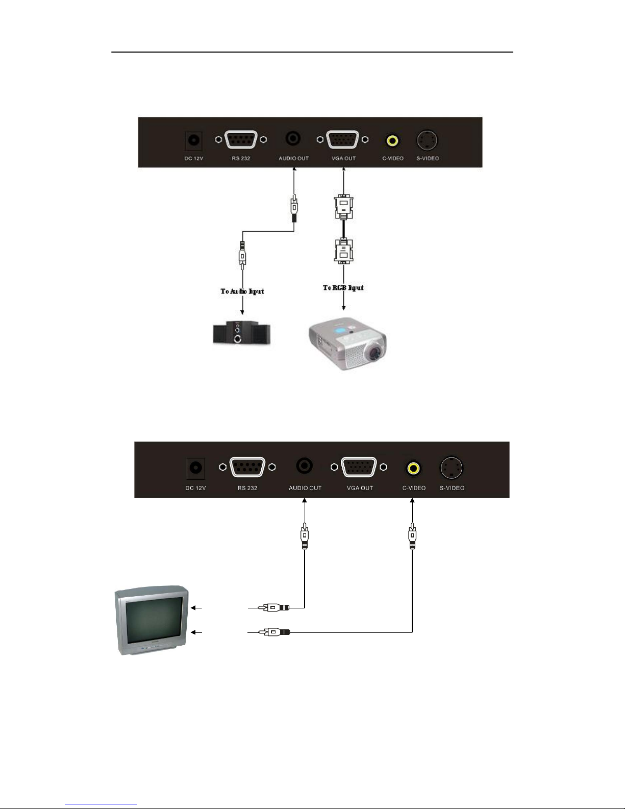
5.2. VGAOUTPUT CONNECTION......................................................................................10
5.3. C-VIDEO OUTPUT CONNECTION..............................................................................10
5.4. S-VIDEO OUTPUT CONNECTION..............................................................................11
6. COMMUNICATE WITH COMPUTER..........................................11
6.1. COMPUTER REQUIREMENTS....................................................................................11
6.2. CONTROLVIA RS232 ...................................................................................................11
6.3. USB CAMERA................................................................................................................18
7. FEATURES .........................................................................................31
LIGHT.....................................................................................................................................31
ZOOM INAND ZOOM OUT ................................................................................................31
FOCUS ADJUSTMENT.........................................................................................................31
BRIGHTNESS ADJUSTMENT.............................................................................................31
WHITE BALANCEADJUSTMENT.....................................................................................31
TEXT/PICTURE MODE........................................................................................................31
IMAGE FREEZE....................................................................................................................32
IMAGE MIRROR...................................................................................................................32
SPLIT SCREEN......................................................................................................................32
IMAGE SAVE.........................................................................................................................32
IMAGE RECALL...................................................................................................................32
MULTIPLE INPUTS AND OUTPUTS..................................................................................33
USB 2.0 PORT........................................................................................................................33
USB IMAGE CAPTURE AND VIDEO RECORDING.........................................................33
RS232 CONTROL..................................................................................................................33
8. SPECIFICATION...............................................................................33
9. TROUBLE-SHOOTING: ..................................................................34
10. PACKING LIST................................................................................35
3

1
.
PARTS
IDENTIFICATION
1. Remote control IR receiver
2. Camera
3. LED light box
4. Upper mechanical arm
5. Main mechanical arm
6. Side panel
7. Back panel
8. Base unit
9. Control panel
4

2.
CONTROL
PANEL
1. POWER: Turn on/off the power.
2. HOME: Activate VGA output terminal, providing the image from camera.
3. LAMP: Turn on/off the LED light.
4. FREEZE: Freeze/unfreeze the image.
5. T/P: Switch the output image between text mode and picture mode.
6. SPLIT: Split screen, enable the comparison between the frozen image and live image.
7. COMPUTER: Activate the VGA input.
8. VIDEO: Activate the C-VIDEO&S-VIDEO output, providing the image from camera.
9. BRIGHT+/-: Image brightness adjustment.
10. PAGE DOWN: Saved image page down when image recall mode is enabled.
11. AUTO: Automatically adjust focus, color and white balance.
12. SAVE: Capture and save the current image.
13. RECALL: Image recall mode enabled, display the saved images.
In Image Recall mode:
1: Display the first image.
2: Display the second image.
3: Display the third image.
4: Display the fourth image.
14. FOCUS+/-: Adjust focus manually, focus far and focus near.
15. ZOOM+/-: Image zoom in and zoom out control.
5

3.
INPUTS
AND
OUTPUTS
1. DC 12V: Power input.
2. RS 232: Serial port, to control the document camera from a computer via this port.
3. AUDIO OUT:Audio output.
4. VGA OUT: VGA (RGB) signal output (15 pin D-SUB).
5. C-VIDEO: Composite video output.
6. S-VIDEO: S-Video output.
7. VGA IN: VGA(RGB) signal input(15 pin D-SUB).
8. AUDIO IN: Audio input.
9. USB: Capture image into a connected computer via provided software
6

4.
REMOTE
CONTROL
7

1. : Turn the document camera on or off.
2. Computer: Press this button to output signals from VGA-IN.
3. Video: Activate the VIDEO&S-VIDEO output, providing the image from camera.
4. XGA/SXGA: Toggle the output format between XGAand SXGA.
5. Home: Output the image from the document camera.
6. Number Buttons:
In image recall mode:
1: Display the first image.
2: Display the second image.
3: Display the third image.
4: Display the fourth image.
7. : Turn the LED light on or off.
8. Mir: Output right-and-left, up-and-down mirror image.
9. Save: Capture the current image.
10. Recall: Enter the Image Recall mode to display saved images.
11. Page +/-: in Image Recall mode, navigate between pages of thumbnail images.
12. Auto:Automatic adjust focus, color and white balance.
13. Split: Split screen, enable the comparison between the frozen image and live image.
14. Zoom+/-: Image zoom in and zoom out control.
15. Frz: Freeze/unfreeze the image.
16. Bri+/-: Image brightness adjustment.
17. T/P: Switch the output image between the text mode and picture mode.
18. Fc+/-:Adjust focus manually, focus far and focus near.
20. Sharp+/-:Adjust sharpness of the image.
21. Blue+/-: Image color adjustment (blue).
22. Red+/-: Image color adjustment (red).
8

5.
CONNECTIONS
5.1.
COMPUTER
CONNECTION
RS232
cable
To
RS232
USB
Audio
Cable
To
Audio
Output
To
RGB
Output
9

5.2.
VGA
OUTPUT
CONNECTION
5.3.
C-
VIDEO
OUTPUT
CONNECTION
Audio
Cable
To
Audio
Input
To
Video
Input
Video
Cable
10

o
5.4.
S-VIDEO
OUTPUT
CONNECTION
S-Vide Cable
Audio Calbe
To Audio input
To S-Video in
6.
COMMUNICATE
WITH
COMPUTER
6.1.
COMPUTER
REQUIREMENTS
The PC's hardware and software configurations shall not be less than the following requirements:
Operating system: Windows XP
CPU: 1.8 GHz
Physical memory: 512M
Video memory: 64M
6.2.
CONTROL
VIA
RS232
PV 380 can be controlled from a computer via RS232.
1. Double click on the RS232 software in provided CD to run the install shield wizard.
11

Then you will see the software setup window:
Read terms, select "I accept the terms in the license agreement" Click on Next:
Click on Change to change the installation directory if needed, then click on Next:
12

Click on Install to install the software to the computer:
Click on Finish, the software installation is complete:
13

2. Connect the computer to the PV 380 with a RS232 cable, turn on the power of PV 380.
3. Double click on or click on start->All Programs->Visualizer_RS232->
Visualizer_RS232.exe to run the RS232 software, You will see the icon on the task bar and the
control interface on the top right of the screen:
: Zoom+
: Zoom-
: Auto
: Display all functions
: Minimize
: Close
4. Click on , you will see the following control panel.
14

5. Properly set the software.
:
: Select corresponding model number.
Select the right COM port.
Note:
* If the selected model does not have certain functions, the corresponding buttons in the software
interface are displayed in light gray and are not clickable.
* All models require 15 seconds start-up time to start the software.
15

6. Button instruction
P
P
P
F
B
B
F
F
P
P
R
R
B
B
S
Button Function
ower On Power on the unit
ower Off Standby
Home Switch to visualize mode
Video Out Switch to Video/S-Video output
C In Active PC input
reeze Image freeze
Light Toggle between arm light and no light
rightness+
Increase the brightness
rightness- Decrease the brightness
ocus+ Focus far
ocus- Focus near
Zoom+ Zoom in
Zoom- Zoom out
age+ Page up
age- Page down
ed+ Increase the red hue
ed- Decrease the red hue
lue+ Increase the blue hue
lue- Decrease the blue hue
harpness+ Increase the sharpness
16

S
S
R
S
M
X
harpness- Decrease the sharpness
Auto Auto focus, brightness, and color
ave Save image
ecall Recall saved images
plit Split screen
irror Mirror image
T/P Switch between text and image modes
GA Switch between SXGA and XGA output modes
1 Display Image #1(in image recall mode)
2 Display Image #2(in image recall mode)
3 Display Image #3(in image recall mode)
4 Display Image #4(in image recall mode)
17

6. 3USB CAMERA
1、SOFTWARE INSTALLATION
Click to run the software installation package, the following dialogue appears, click "Next":
Read the terms, Select "I accept the terms in the license agreement." Click "Next", as the following figure.
The following dialogue box appears, click "Next":
18

The default installation directory is Program Files, C: \ Program Files \, you can select a different
installation directory, as shown:
Click "Change" to change the directory, as shown:
19

Click "OK", the following figure appears. Click "Next".
Click "Install" to complete installation, as shown:
20
Table of contents