Fig. 2 Input port circuit ( Yin connection)
PC PNP output
Note: When VCC=5V, R=0
When VCC=12V, R=1K, >1/8W
When VCC=24V, R=2K,>1/8W
R must connect in the control signal part .
3.Function choice ( Using DIP pins to achieve this function)
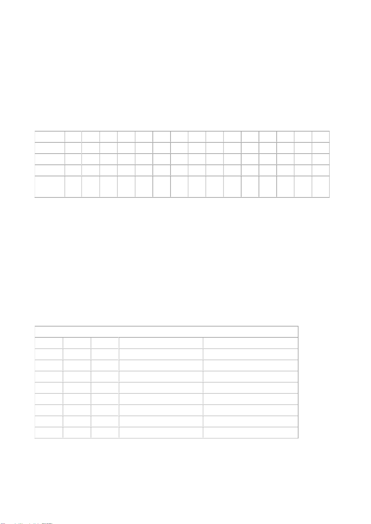
1) Micro step resolution is set by SW 5,6,7,8 of the DIP switch as shown in the following table:
2) Standstill current setting
SW4 is used for this purpose. OFF meaning that the standstill current is set to be half of the se
lected dynamic current and ON meaning that standstill is set to be the same as the selected dy
namic current.
3) Output current setting:
The first three bits (SW 1, 2, 3)of the DIP switch are used to set the dynamic current.
Select a setting
Closest to your motor’s required current
4) Semi-flow function:
Semi-flow function is that there is not step pulse after 500 ms, the driver output current
automatically reduced to 70% of rated output current, which is used to prevent motor heat.
4. Pins of motor & power: