Installation instructions
KNX Gateway
Keep for future use!
Valid from 01 September 2012
2003866_0•en•01.09.2012 We reserve the right to carry out improvements 1
Safety instructions
ARNINGW
The electrical installation must be
performed by a certified electrician in
accordance with the electrical installation
regulations published by the Association
of German Electrical Engineers (VDE0100)
or the standards and regulations of the
country in which the device is being
installed. The electrician must observe the
installation instructions included with the
electrical devices.
ARNINGW
If hazard-free operation cannot
be assumed, the device may not
be commissioned or must be
decommissioned. This assumption is
justified if
If the housing or the supply lines show
signs of damage,
The device is no longer working.
ARNINGW
It is important to comply with the following
points in the interest of personal safety.
Children may not play with the operating elements of
the control unit or the remote control! Store the remote
controls out of the range of children.
Make sure that no persons or objects are in the range
of movement of the driven parts (blinds, external
venetian blinds, etc.)!
Disconnect the device from the operating voltage
if cleaning or other maintenance work must be
performed.
Function
These functions are integrated in the software. A detailed
description can be found in the KNXGateway manual. The
manual and product database of the KNX Gateway can be
downloaded from www.warema.com.
Installation
The device is intended for installation in a distribution
cabinet. The unit is mounted by clipping it onto a DIN rail
(TH 35/DIN 60715).
General information
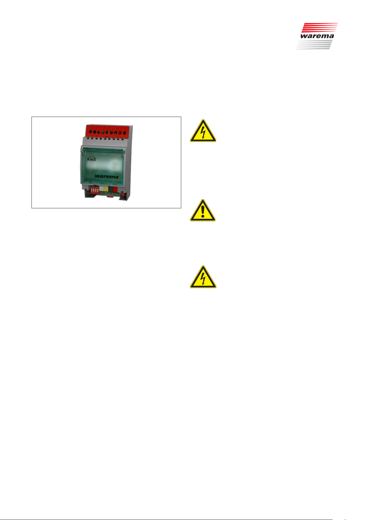
Fig. 1 KNXGateway
The KNX Gateway enables the use of WAREMA
climatronic® as a central control unit in a KNX bus system.
It transmits the move commands, weather data and status
information of the WAREMA climatronic® to the KNX
bus. The KNX Gateway can also read out certain status
information from the KNX bus and make it available to the
WAREMA climatronic® control panel.
Control parameters can readily be changed directly on
the WAREMA climatronic® control panel without it being
necessary to set parameters on the KNX side (e.g. by
means of ETS).
A KNX Gateway can address 16 channels. By using
multiple KNX Gateways, all channels of the WAREMA
climatronic® can be implemented on the KNX bus.
The KNX Gateway is supplied with 24VDC via the
WAREMA climabus.
The KNX Gateway can only be used in conjunction
with the WAREMA climatronic 2.0 control panel. Older
versions of the WAREMA climatronic are not suitable
and cannot be upgraded with a software update.
Intended use
The device was developed to control sun shading
systems. The approval of the manufacturer must be
obtained for uses outside of the purposes listed in these
instructions.
The KNX Gateway is intended for installation in enclosed
electrical operating facilities.


