WARPP ENGINEERS PVT LTD
36/15,UNIQUE INDL ESTATE ,DHUMAL NAGAR ,WALIV PHATA ,VASAI(EAST)
C NO -8080808734
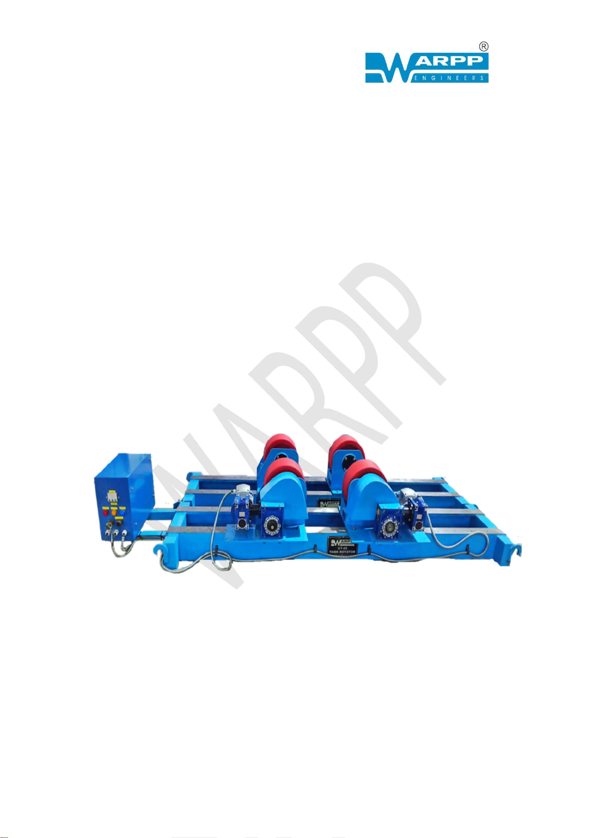
2. PRODUCT DESCRIPTION & FEATURE
The Conventional Rotator is designed to aid the welding of
cylindrical vessels.
A Conventional Welding Rotator consists of two (2) parts:
• A Motorized drive (power) unit; and
• An Idler supporting unit.
The power unit is driven by a heavy duty geared AC motor
which is designed according to internationally proven
specifications to ensure constant speed.
The heavy-duty Wheels are Coated with Poly urethane coating
with a shore hardness of 90. These coatings not only absorb
shock during placement of shells but also provide required
friction for proper rotation of the job. These coating are also
required when SS jobs are welded as contact of these metal
with CS wheel result in carbon inclusion.
By using independent drive & idler units, vessels of varying
lengths can be placed on the Rotators supported on the
Rotator wheels. The wheel can be adjusted on the base frame
to accommodate different vessel diameter.
Tank Rotators are usually arranged in sets including a pair of
identical rolls, one of the which is rotated by an electric motor
through a reduction gearbox, known as powered unit or drive
unit while the other is idler, so arranged that the distance
between the rolls can be adjusted to accommodate vessels of
different diameters.