Waste King 560C396P01 User manual

Food Waste Disposer
Owner s Guide
IMP RTANT - Read all instructions thoroughly. Keep this guide for
future reference.
CAUTI N - Be sure to review SAFETY INSTRUCTI NS PERTAINING T
A RISK F FIRE, ELECTRICAL SH CK R INJURY T PERS NS before
installing disposer.
CONGRATULATIONS. YOU HAVE PURCHASED THE
#1 PERFORMANCE LEADER IN FOOD WASTE DISPOSERS.
Our food waste disposer is a reliable appliance that will offer your household many years of
trouble free use. This disposer has been uniquely designed to free your kitchen of all organic
food waste left over after the preparation and clean-up of meals. Simply turn on the water,
switch the disposer on, put your food waste in the disposer and it will shred the garbage into
very fine particles that are easily flushed through the sewer system without any problem. For
Batch Feed Operations, please see Section 6 of this manual.
Before installing and operating this disposer:
1. Make sure that the installation of this appliance is allowed by the authorities.
2. Please read and follow all recommendations in this manual to ensure
trouble free operations.
f you have any questions, please contact your distributor.
1MOUNTING ASSEMBLY
2ELECTRICAL CONNECTIONS
3DISHWASHER CONNECTION
4ATTACHING THE DISCHARGE ELBOW
5CONNECTING DISPOSER TO MOUNT ASSEMBLY
6OPERATING INSTRUCTIONS
7TROUBLESHOOTING
8CLEANING AND MAINTENANCE
TABLE OF CONTENTS
560C396P01 REV C

INSTRUCTI NS PERTAINING T RISK F FIRE, ELECTRIC SH CK R INJURY T
PERS NS. SAVE THESE INSTRUCTI NS.
1. Read all instructions before using
the appliance.
2. To reduce the risk of injury, close
supervision is necessary when an
appliance is used near children.
3. Do not put fingers or hands into a
waste disposer while it is functioning.
4. Turn the power switch to the off position
before attempting to clear a jam or
remove an object from the disposer.
5. When attempting to loosen a jam in a
waste disposer, use a long wooden
spoon or a broom handle.
6. When attempting to remove objects
from a disposer, use long-handled
tongs or pliers.
7. To reduce the risk of injury by materials
that might be expelled by a waste
disposer, or damage to it, do not put
the following in the disposer:
a. Clam or oyster shells
b. Drain cleaner
c. Glass, china or plastic
d. Large whole bones
e. Metal, such as bottle caps,
tin cans or aluminum foil
f. Whole corn husks
g. Tea or coffee bags
8. When not operating the disposer, leave
the stopper in place to reduce the risk
of objects falling into the disposer.
9. Do not operate disposer unless
splash guard is in place. Not applicable
to Batch Feed models.
10. For proper earthing instructions
see the ELECTRICAL C NNECTI N
portion of this manual.
11. f you are not familiar with electrical
power and procedures, call a qualified
electrician.
12. The symbol on the product or on its
packaging indicates that this product may
not be treated as household waste.
nstead, it shall be handed over to the
applicable collection point for the recycling
of electrical and electronic equipment. By
ensuring this product is disposed of
correctly, you will help prevent potential
negative consequences for the
environment and human health, which
could otherwise be caused by
inappropriate waste handling of this
product. For more detailed information
about recycling of this product, please
contact your local city office, your
household waste disposal service or the
shop where you purchased the product.
WARNING - When using electrical appliances, basic precautions should always be followed,
including the following:
IMPORTANT SAFETY INSTRUCTIONS
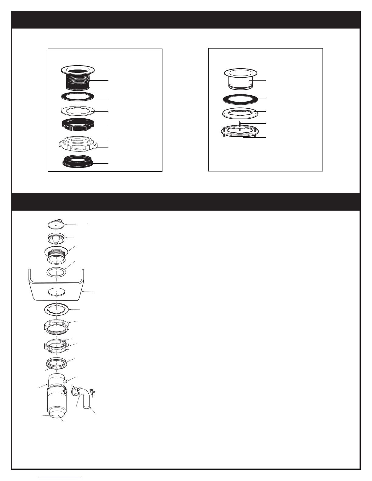
INSTALLATION OF EZ MOUNT ASSEMBLY
STOPPER
REMOVABLE
SPLASH GUARD
S NK FLANGE
RUBBER S NK
FLANGE GASKET
S NK
SUPPORT R NG
NOTE: ARROWS
ND CAT NG UP
CUSH ON MOUNT
GROOVE D SHWASHER
D SCHARGE NLET
HOPPER
ELBOW GASKET
END BELL
(ELECTR CAL
CONNECT ONS)
ELBOW
FLANGE
SCREWS
D SCHARGE
ELBOW
SER AL NUMBER
LOCATED HERE
(Read completely before starting.)
N TE: Pay close attention to the order of mount assembly parts,
as they have been correctly assembled by the factory.
Also, reference the cushion mount detail illustration below for
the proper orientation of the cushion mount.
A. Disassemble mount assembly from disposer by turning mount ring
to the left (clockwise) and remove.
B. Raise mount ring toward top of sink flange. Remove cushion
mount. Remove mount ring. You may want to practice installing
the cushion mount at this point before you are under the sink.
See paragraph "H."
C. Unscrew support ring from sink flange and remove fiber gasket.
You are now left with sink flange and rubber gasket.
D. The rubber gasket is used instead of plumbers putty with
stainless steel sinks. ther sinks may require putty.
E. f no putty is used, insert sink flange through rubber gasket into
sink opening. Do not rotate sink flange once it is seated.
F. f you use putty instead of the gasket, form a ring around
underside of sink flange. nsert flange into sink opening, press
down hard to squeeze out excess putty. From under sink, trim off
excess putty flush with bottom edge of sink opening.
G. From underneath sink, slip fiber gasket onto exposed sink flange.
With arrows pointing up, screw support ring onto the sink flange,
hand tighten until the sink flange will not move (see 1A). At this
point you may want to insert stopper in sink and fill with water to
check sink flange seal and insure there are no leaks.
‡ MOUNT R NG
T GHTEN NG EARS
*Batch feed stopper looks different than stopper
shown here (see Section 6).
** Not applicable to batch feed models.
‡ Mount ring may look different and may not have
tightening ears.
F BER GASKET
**
*
YOUR DISPOSER COMES WITH ONE OF THE FOLLOWING MOUNT SYSTEMS
Proceed to the in truction for your type of mount y tem.
3-Bolt Mount System
EZ Mount System
SINK FLANGE
SINK FLANGE GASKE
PRO EC OR RING
FIBER GASKE
SINK MOUN RING
MOUN ING SCREWS (3)
SUPPOR RING
MOUN RING
IGH ENING EARS
CUSHION MOUN
SINK FLANGE*
SINK FLANGE GASKE
* An extended sink flange (Item # 3140) is
available for deep-well, cast iron sinks. (For
3-bolt mount only.)
1
INSTALLATION OF MOUNTING ASSEMBLY

INSTALLATION OF EZ MOUNT ASSEMBLY CONT.
SUPPORT R NG
S NK
FBER
GASKET
MOUNT R NG SHOULD BE
FREE TO MOVE UP & DOWN
OPEN AREA, NO
OBSTRUCT ON
S NK FLANGE
BEAD OF
CUSH ON
MOUNT
1A 1B 1C RUBBER GASKET
SNK
FLANGE
H.Place mount ring over sink flange and hold in place
while installing cushion mount (large side down) so
the groove on the
inside of cushion
mount fits over lip on
sink flange, similar to
putting the lid on a
plastic container (see
cushion mount detail
& 1B).
Run fingers around entire cushion mount with
slight pressure. Do not press too hard. When
cushion mount is properly seated, mount ring can
be pulled downward over cushion mount and will
be free to rotate. llustration 1C shows correct
installed position.
TOP
BOTTOM
BEAD
GROOVE
CUSHI N M UNT DETAIL
NOTE: Pay close attention to the order of mount assembly parts,
as they have been correctly assembled by the factory. (See 1D
and 1E.)
A. Disassemble the mounting assembly, as it has been shipped,
by turning the sink flange until the projections align with the
notches in the mount ring and allow you to pull the sink
flange up and out of the remaining mount assembly. Note the
sequence of these parts as they are stacked and refer to 1D
and 3B to identify each part. Unpack the 3 mount screws and
screw them half way through the mount ring (notice “TH S
S DE UP” is imprinted on top of the mount ring).
Next, stack the rubber gasket on top of the protector ring and
sit them on top of the pointed ends of the mount screws.
B. Keep these assembled parts together and set aside. Before
you connect the disposer to the mount assembly under the
sink, you may want to practice engaging the groove of the
Hush Cushion® to the ridge at the bottom of the sink flange.
C. Be sure your sink is clean. Pack the underside rim of the sink
flange with plumberʼs
putty (see 1F).
Position the sink
flange so it is
centered and
readable as you look
into your sink. Push
the sink flange firmly
into the sink opening
READ C MPLETELY BEF RE STARTING
INSTALLATION OF 3-BOLT MOUNT ASSEMBLY
1D
S OPPER*
SINK FLANGE**
SINK
HOPPER
ELBOW
GASKE
SCREWS
SERIAL #- RECORD ON
WARRAN Y CARD
MOUN ING
SCREWS**
SCREW
CLAMP**
PROJEC IONS
RIDGE
RIDGE
DISCHARGE
ELBOW
ELBOW
FLANGE
DISHWASHER
DISCHARGE INLE
HUSH CUSHION®**
RUBBER SINK
FLANGE GASKE **
PRO EC OR RING**
MOUN RING**
PLUMBER’S
PU Y
END BELL
(ELEC RICAL
CONNEC IONS)
MOUN ING
SCREWS
PRO EC OR
RING RUBBER
GASKE
SINK
FLANGE
HUSH CUSHION
1E
SCREW
CLAMP
MOUN ING
RING
Mount Assembly
* Batch Feed Stopper looks different than the stopper illustrated.
** Mount Assembly (see 3B)

to make a good seal. DO NOT move or rotate
the sink flange once seated or the seal may be
broken.
D. Take the remaining portion of the mount assembly,
as it was set aside and make sure that the rubber
gasket is on top of the protector ring. From
under the sink, while holding the sink flange
firmly with one hand, line up the notches in
the mount ring with the projections of the sink
flange. Slide the mount assembly up onto the
sink flange, past the projections and give the
mount assembly a 1/4 turn, so that it will hang by
itself (see 1G).
E. Tighten the 3 mounting screws evenly with a
screwdriver (see 1H). DO NOT OVERT GHTEN!
Trim off excess putty.
ENDBELL RED RESET
BUTTON
EARTH
SCREW
W RE NUTS
REMOVE
COVER PLATE
2
ELECTRICAL CONNECTIONS
INSTALLATION OF 3-BOLT MOUNT ASSEMBLY CONT.
1H
1G
1F
N TE: A qualified electrician is
required. Disconnect electric power
to disposer circuit before installation.
Turn the circuit breaker to the OFF
position or remove the fuse.
For permanently connected
appliances:
EARTHING INSTRUCTI NS
This appliance must be connected
to an earthed, metal permanent
wiring system; or an equipment
earthing conductor must be run with
the circuit conductors and
connected to the equipment -
earthing terminal on the disposer.
A. Connect disposer to AC current
only.
PLEASE N TE: The Food Waste
Disposer in this carton is designed
to operate at the voltage indicated
on the cover plate located at the
bottom of the disposer. This plate
also includes related electrical and
identification information.
B. f you use flexible metal
shrouded cable:
nstall cable connector in hole.
PLEASE N TE:
Black or brown wire of disposer
- L VE
White or blue wire of disposer
- NEUTRAL
Green or yellow/green wire
and earth screw of disposer
- EARTH
Connect wires according to the
color code indicated on the
endbell illustration.
See diagram below.
f flexible metal shrouded cable
is not used, provide a separate
earth wire to the nearest cold
water metal pipe or other
suitable earth, using screw in
bottom endbell for the earth
wire.
C. f plug-in cord is used, it should
have an earthed plug or a plug
with an earth wire attached for
connection to the earth screw at
the bottom of the endbell.
D. Use a cable clamp strain-relief
connector similar to the one
shown, at the point where the
power cord enters the disposer
(see 2A).
E. f your power supply does not
include an earth wire, you must
supply one unless metal cable is
used. Attach a copper wire
securely to disposer earth screw
and attach other end of wire to a
metal cold water pipe. f plastic
pipe is used in your home, a
qualified electrician should
install a proper earth.
STRA N
REL EF
NUT
2A
•The appliance in this carton is
designed to operate at voltages
between 220-240 volts, 50/60Hz.
•For electrical rating please refer to
the serial number label located on
the bottom of the disposer.
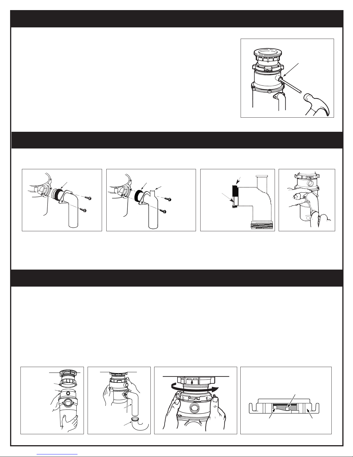
A. Connect waste elbow to disposer (see 4A or 4B), proceed to step 5 and then connect bottom of elbow
by tightening slip nut.
B. Make sure all plumbing connections are tight.
A. Line up disposer under mount assembly. Guide hopper projections into mount ring slots (see 5A).
Turn mount ring about 6mm to right so that disposer is temporarily supported.
B. Turn mount ring and disposer until waste elbow lines up with outlet pipe (see 5B).
C. Turn mount ring to the right until it locks up tight (see 5C). Hopper projections must be to extreme
left of mounting slots (see 5D).
D. f mount ring is hard to turn, you may add a small amount of petroleum jelly or liquid soap to hopper
projection. Run water and check for leaks.
f you are utilizing a dishwasher, complete the following procedure.
f dishwasher is not to be connected go on to step 4.
A. Using a blunt instrument (steel punch or wooden dowel), knock
out entire plug (see 3A). Do not use a screwdriver or sharp
instrument. When knockout plug falls into disposer, you may
remove it or simply grind it up when the disposer is used. This
will not damage the disposer in any way, but may take some time
to grind, over the course of several uses.
B. Connect dishwasher hose using hose clamp. f hose size is
different, you will need a stepped rubber adapter.
L CKING DETAIL
RUBBER GASKET
KNOCK
OUT
PLUG
HOPPER PROJECT ON N
“SUPPORTED” POS T ON
HOPPER PROJECT ON
N “LOCK” POS T ON
MOUNT
R NG
3
DISHWASHER CONNECTION (IF REQUIRED)
4
ATTACHING DISCHARGE ELBOW (IF REQUIRED)
5
CONNECTING DISPOSER TO EZ MOUNT ASSEMBLY
3A
5C5B5A 5D
4C
4A RUBBER
GASKET OVERFLOW
NLET
4B
SLOT
PROJECT ON
ELBOW
OUTLET
P PE
Your disposer comes with a discharge elbow of either configuration 4A or 4B.
GASKET
ENGAGE
NNER
GROOVE
OF
GASKET
W TH
FLANGE
OF
ELBOW

THIS DISP SER UTILIZES ANTI-JAM SWIVEL IMPELLERS THAT MAKE A CLICKING S UND AS THEY
SWING INT PLACE. THIS INDICATES N RMAL PERATI N.
BATCH FEED MODELS:
LARGE
SMALL
MED UM
6
OPERATING INSTRUCTIONS
6A 6B 6C 6D
CONNECTING DISPOSER TO 3-BOLT MOUNT ASSEMBLY
A. Remove sink stopper. Turn on
cold water using a medium flow.
B. Turn switch to ON position; your
motor is turning at full speed
and ready to use.
C. Scrape in food waste. Down the
drain go table scraps, peelings,
cobs, rinds, seeds, pits, bones
and coffee grounds. To speed up
food waste disposal, cut or
break up large bones, rinds and
cobs. Large bones and fibrous
husks require considerable
grinding time and are more
easily thrown away with other
trash. Do not be alarmed that
the disposer slows down while
grinding. The disposer is actually
increasing torque (grinding
power) and is operating under
normal conditions.
D. Before turning disposer off, let
water and disposer run for
approximately 25 seconds after
shredding stops. This assures
that all waste is thoroughly
flushed through trap and drain.
E. t is not recommended to use
hot water while running
disposer. Cold water will keep
food waste and fats solid so dis-
poser can flush away particles.
F. PM4 model is designed for
intermittent usage only and is
not rated for continuous
commercial usage.
A. Remove sink stopper and turn
on a medium flow of cold
water (see 6A).
B. Scrape in food waste. Down
the drain go table scraps,
vegetable peelings, cobs, rinds,
pits, bones and coffee grounds
(see 6B).
C. nsert stopper to start disposer
(see 6C). One of the two
small slots in stopper base
must line up with switch plunger
inside the neck of the disposer.
Push down firmly. Lift stopper to
shut disposer off.
D. Run disposer for 25 seconds
after shredding stops.
This assures that all waste is
thoroughly flushed through trap
and drain.
E. To fill sink, insert stopper so that
largest slot lines up with switch
plunger (see 6D). Stopper can
now be pushed down to seal
sink without actuating disposer.
When medium sized slot (see 6C)
in stopper base is lined up with
the switch plunger, water can
drain, but tableware, etc.,
cannot be accidentally dropped
into disposer.
A. Press firmly around the Hush Cushion® to ensure
it is engaged with the neck of the disposer.
B. Lubricate the top inside lip of the rubber Hush
Cushion® with a liquid soap.
C. Line up discharge elbow of disposer with trap
under mounting assembly. Guide disposer up and
engage the groove of the Hush Cushion® around
the ridge at the bottom of the sink flange (see 5E
& refer back to 3B). While still supporting the dis-
poser, tighten the screw-clamp around Hush
Cushion®. The disposer will now hang by itself.
D. f you need to turn the disposer make sure the sink
flange does not turn. t will break the seal created
when installed. Go back to steps 5A and 5B.
IMP RTANT – PLEASE READ
Do not remove clamp from Hush Cushion® or
Hush Cushion® from hopper. Both parts are factory
installed and installation ready.
Lubricate top angled surface of
rubber Hush Cushion® with liquid
soap prior to engaging disposer
to sink flange. Fit Hush Cushion®
lip into sink flange groove using a
slight rocking motion. Tighten
clamp (see 5F).
5F
SINK FLANGE
CLAMP
HUSH CUSHION®
OP ANGLED
SURFACE
HUSH
CUSHION®
5E
SINK
FLANGE
GROOVE
CLAMP
HOPPER

Before seeking repair or replacement, we recommend that you review the following:
L UD N ISES (Other than those during grinding of bones and fruit pits): These are usually caused by
accidental entry of a spoon, bottle cap or other foreign object. To correct this, turn off disposer and water. After
disposer has stopped, remove *splash guard, remove object with long handled tongs, and replace *splash guard.
UNIT D ES N T START: Unplug power cord or turn either the wall switch or breaker box switch to “off”
position, depending on your model and wiring configuration. With *splash guard removed, check to see if
turntable will rotate freely using a broom handle. f turntable rotates freely, replace *splash guard and check
reset button to see if it has been tripped. Reset button is red and located opposite discharge elbow, near the
bottom (see 7A). Push button in until it clicks and remains depressed.
f reset button has not been tripped, check for shorted or broken wire connecting to disposer. Check
electrical power switch, fuse box or circuit breaker. f wiring and electrical components are intact, the unit may
have internal problems that require service or replacement.
IF TURNTABLE D ES N T R TATE FREELY: Check for foreign object lodged between the turntable and grind
ring. Dislodge object by rotating table with a broom handle and remove object (see 7B). f no foreign object is
present, there may be internal problems.
LEAKS: f the unit leaks at the top, it may be due to:
1. mproper seating of sink flange (gasket choice, putty or tightening.)
2. Support ring not tightened properly.
3. Defective cushion mount.
f unit leaks at the waste elbow, leak may be due to improper tightening of elbow flange screws.
*Splash guard is not used with Batch Feed units.
RESET
BUTTON
SER AL NO.
REMOVE
SPLASH GUARD
TURNTABLE
7
TROUBLESHOOTING
7B7A
TIPS - Helpful Hints
1.Be sure disposer is empty
before using your dishwasher so
it may drain properly.
2. You may want to leave the stop-
per in the drain when not in use
to prevent utensils and foreign
objects from falling into the dis-
poser.
3. Use it wisely! Your disposer is
ruggedly built to give you years
and years of trouble-free serv-
ice. t will handle all normal food
wastes–BUT it will not grind and
dispose such items as tin cans,
bottles and bottle caps, glass,
china, leather, cloth, rubber,
string, feathers, clam or oyster
shells, or stringy or fibrous food
waste. These are waste materi-
als and belong in the trash can
or trash compactor – not inside
your food waste disposer.
4. Use your disposer “before”
and “after” meals! While
preparing food, turn on your
disposer and the cold water,
clearing your sink of vegetable
peelings, or salad trimmings.
When the meal is over, scrape
food scraps directly into the
disposer.
5. TO SPEED UP FOOD WASTE
D SPOSAL... Cut or break up
large bones, melon rinds,
grapefruit skins, corn cobs.
tems such as large bones,
fibrous husks like lima bean
pods and corn husks require
considerable cutting time. For
this reason, you may prefer to
place them in the trash can or
trash compactor.
OPERATING INSTRUCTIONS CONTINUED
8CLEANING AND MAINTENANCE
The motor is permanently lubricated for life. D N T ATTEMPT T LUBRICATE Y UR DISP SER!
The disposer is self cleaning and scours itself with each use.
Your disposer is equipped with a removable **splash guard for ease of cleaning or replacement. Remove splash guard by pulling it out
from the top. To replace, simply insert into sink flange and push down until properly seated.
NEVER put lye or chemical drain cleaners into the disposer, as they cause serious corrosion of metal parts. f used, resulting damage can
be easily detected and all warranties are void.
Mineral deposits from your water can form on the stainless steel turntable of your disposer, giving the appearance of rust. D N T BE
ALARMED, the stainless steel turntables used on PM2S2, PM2L7, PM2A, PM3, PM4, and Batch Feed models will not corrode.
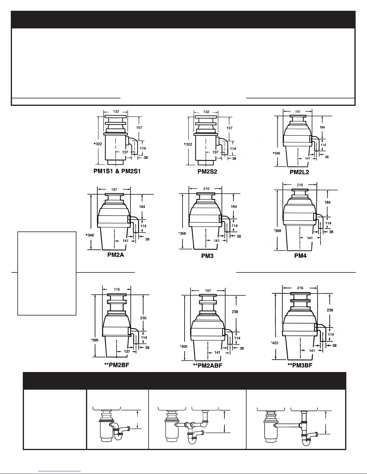
TYPICAL INSTALLATIONS
560C396P01 REV B
SINGLE B WL D UBLE B WL
CENTER UTLET D UBLE B WL
END UTLET
* Approx. * Approx. * Approx.
*229 for models PM2S1
and PM2S2
*254 for models PM2L2,
PM2A, PM3 and PM4
*305 for batch feed
models PM2BF, PM2ABF
and PM3BF.
Choice of trap is optional.
BATCH FEED M DELS
C NTINU US FEED M DELS
N TE:
All dimensions
are in mm.
* Add 16mm for
RF filter.
** Batch Feed
does not use
splash guard.
Table of contents


