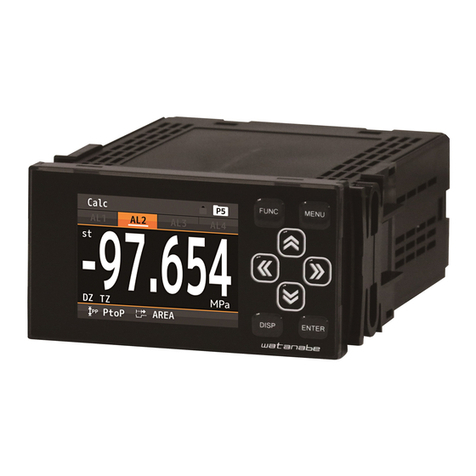
WATANABE WPMZ-3 Series User manual

MODEL WPMZ-3-□□□-□□-□□□ 1/12
IM-0881-04
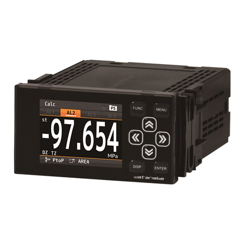
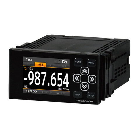
Thank you for purchasing the WPMZ graphical digital panel meter.
This manual is a quick instruction manual only for preparation,
connection and basic condition settings of the WPMZ. For the all
functions of the WPMZ, please refer to a detailed instruction
manual which can be downloaded from our homepage.
For models with RS communication functions, please refer to
"Modbus communication manual" or "RS-232C communication
manual" which also can be downloaded from our homepage.
(https://www.watanabe-electric.co.jp/en/)
Checks before suppling power, preparations, wiring
1. CHECKING THE PRODUCT
1-1. MODEL CODES
Please check that the product has been delivered matches the
model code ordered in reference to “19. SPECIFICATIONS”.
2. PRECAUTIONS FOR USE
2-1. ENVIRONMENTS AND CONDITIONS OF USE
Please do not use the product under the following circumstances.
It might cause malfunctions and shortening the life of the
product.
1)Ambient temperature of out of -5 to 50°C
2)Ambient humidity of out of 35 to 85%, or freezing
condensing
3)Excessive dust or metal particles
(Storing in a dust-proof chassis and a countermeasure
against heat dissipation are required.)
4)Environment of corrosive gas, salty air or oily smoke
5)Environment of much vibration or impact
6)Environment of rain or water drops (except the front
panel)
7)Environment of strong electromagnetic field or much
exogenous noises.
2-2. INSTALLATION AND CONNECTION
1)Please read this manual before the installation and the
connection of wires. And they should be performed by a
person having a specialized technique. In addition, the
insulation class of the WPMZ is as shown by the figure
below. Please confirm that the insulation class satisfies a
use condition prior to the installation.
Reinforced Insulation Basic Insulation
Operational Insulation
AC
power
Comparative outputs, External
control inputs, Analog output, BCD
output,RS-232C
RS-485
Modbus
RTU
Input Ach
Input Bch
Go output
Go output
DC
power
Comparative outputs, External
control inputs, Analog output, BCD
output,RS-232C
RS-485
Modbus
RTU
Input Ach
Input Bch
GO output
GO output
2)Do not wire the power supply line, input signal lines and
output signal lines near noise sources or relay drive lines.
3)Bundling or containing in a same duct with lines including
noises might cause malfunctions.
4)The WPMZ becomes available functionally right after
power activation, but requires 30 minutes' warming to
satisfy all performance requirements.
Note: The inputs “A channel” and “B channel”may be
abbreviated to “Ach”and “Bch”in this manual.
2-3. CHECKING BEFORE USE
Install the WPMZ under the environments and conditions of use
which meet requirements.
If you find any damage to the product or any problem, please
contact to your dealer or our company directly.
3. HOW TO INSTALL (PANEL CUT DIMENTIONS)
To install the WPMZ, panel cut dimensions are as shown by the
figure below.
4. CONNECTING TERMINALS
4-1. BACK VIEW
4-2. WIRING TO SCREWLESS TERMINALS
Pushing the wire release button with a flat-blade screwdriver,
insert the wire to the wire insert hole deeply and then release
the button.
(Suitable tool for pushing buttons :flat-blade screwdriver blade
width 2.5mm)
4-3. CONNECTION FOR LOWER ROW TERMINALS
(COMPARETIVE OUTPUT/EXTERNAL CONTROL
INPUT, POWER)
4-3-1. Comparative Output / External Control Input
-Open-collector output products
No.
Name
Description
1
AL1 c
AL1 open-collector output (collector)
2
AL2 c
AL2 open-collector output (collector)
3
AL3 c
AL3 open-collector output (collector)
4
AL4 c
AL4 open-collector output (collector)
5
AL+COM e
Common terminal for PNP output (emitter)
(NPN output : no connection)
6
AL-COM e
Common terminal for NPN output (emitter)
(PNP output : GND for PNP)
7,8
COM
Common terminal for external control inputs
9
1
External control input No.1
10
2
External control input No.2
11
3
External control input No.3
12
4
External control input No.4
13
5
External control input No.5
Graphical Digital Panel Meter
WPMZ-3-□□□-□□-□□□
Quick instruction manual
120mm min.
70mm min.
+0.6
-0
45
92 -0
+0.8
Ach inputs Bch inputs
Power
Comparetive output/External control input
outputs
UPPER ROW TERMINALS
MIDDLE ROW
TERMINALS
LOWER ROW TERMINALS
Wire insert hole
Wire release button
AL2 (c)
5
COM
AL1 (c)
AL4 (c)
AL3 (c)
COM
AL +COM(e)
AL -COM(e)
1 2 3 4 5 6 7 8 9
10 11 12 13
4
32
1
EXT CONTROL
PNP
NPN
Suitable wire:AWG24 to 16
*⑥、⑦、⑧:connected internally
MODEL WPMZ-3-□□□-□□-□□□ 2/12
IM-0881-04
-Relay output products
AL1・2 COM
COM
AL1
Suitable wire:AWG 24 to 16
AL3
AL2
×
AL3・4 COM
AL4
1 2 3 4 5 6 7 8 9
10 11 12 13
EXT 1
EXT 2
EXT 3
EXT 4
EXT 5
External control inputsRelay outputs
No.
Name
Description
1
AL1
AL1 relay output
2
AL1.2 COM
Common terminal for relay outputs of AL1 and
AL2
3
AL2
AL2 relay output
4
AL3
AL3 relay output
5
AL3.4 COM
Common terminal for relay outputs of AL3 and
AL4
6
AL4
AL4 relay output
7
×
NC
8
COM
Common terminal for external control inputs
9
EXT 1
External control input No.1
10
EXT 2
External control input No.2
11
EXT 3
External control input No.3
12
EXT 4
External control input No.4
13
EXT 5
External control input No.5
4-3-2. Supply Power
No.
Name
Description
P1
POWER
(+)
Power source terminal
(In case of DC power, +V)
P2
POWER
(-)
Power source terminal
(In case of DC Power, 0V)
P3
FG
(NC)
FG terminal
(DC power option: no connection
( Non-usable for a relay terminal))
4-4. CONNECTION FOR UPPER ROW TERMINALS
4-4-1. 4 Wire Type Straingauge Input / GO Output
*Screwless connector
+EXC
-SIG
+SIG
GND
Ach Straingauge input
Suitable wire:AWG 24 to 16
-EXC
+EXC
-SIG
+SIG
GND
Bch Straingauge input
Suitable wire:AWG 24 to 16
-EXC
20
14 15 16 17 18 19 27
21 22 23 24 25 26
GO.OUT
GO.GND
GO.OUT
GO.GND
●Straingauge input / GO output(Ach,Bch)
No.
Name
Description
14,21
+EXC
Bridge power supply(+)
15,22
-SIG
Input(-)
16,23
-EXC
Bridge power supply(-)
17,24
+SIG
Input(+)
18,25
GND
GND
19,26
GO.OUT
GO output(collector)
20,27
GO.GND
GO output(emitter)
* When bridge power supply is 5V or 2.5V, -EXC and GND are
connected internally.
・Example for input connections
+EXC
-EXC
+SIG
-SIG
GND
+IN
-IN
+OUT
-OUT
Bridge circuit
WPMZ-3
Straingauge input
10V
(5V)
(2.5V)
4-4-2. Process Input / GO Output
*Screwless connector
Ach Process input
Suitable wire:AWG 24 to 16
GO.OUT
GO.GND
V HI
LO
+EXC
-EXC
A HI
Bch Process input
Suitable wire:AWG 24 to 16
GO.OUT
GO.GND
V HI
LO
+EXC
-EXC
A HI
20
14 15 16 17 18 19 27
21 22 23 24 25 26
※⑮、⑱ : connected internally ※ 、 : connected internally
22 25
●Process input / GO output(Ach,Bch)
No.
Name
Description
14,21
V HI
Voltage input(+)
15,22
LO
Input(-)
16,23
A HI
Current input(+)
17,24
+EXC
Sensor power supply(+)
18,25
-EXC
Sensor power supply(-)
19,26
GO.OUT
GO output(collector)
20,27
GO.GND
GO output(emitter)
*LO and -EXC are connected internally.
4-5. CONNECTION FOR MIDDLE ROW TERMINALS
4-5-1. Analog Output *Screwless connector
●WPMZ-3-□□□-1□-□□□
No.
Name
Description
28
V.OUT
Analog voltage output terminal (+)
29
V.COM
Analog voltage output terminal (-)
30
NC
No connection
*Non-usable for a relay terminal
31
A.OUT
Analog current output terminal (+)
32
A.COM
Analog current output terminal (-)
33,34
NC
No connection
*Non-usable for a relay terminal
4-5-2. BCD Output
●WPMZ-3-□□□-2or3□-□□□
No.
Name
Description
1 to 4
1001-8
Bit 1-8 of BCD 100 digit output terminals
5 to 8
1011-8
Bit 1-8 of BCD 101 digit output terminals
9 to 12
1021-8
Bit 1-8 of BCD 102 digit output terminals
13 to 16
1031-8
Bit 1-8 of BCD 103 digit output terminals
17 to 20
1041-8
Bit 1-8 of BCD 104 digit output terminals
21 to 24
1051-8
Bit 1-8 of BCD 105 digit output terminals
25
POL
BCD polarity output terminal
26
OVER
BCD over output terminal
27
PC
BCD synchronous signal output terminal
28
ENABLE
BCD enable terminal
By bringing to same voltage level of -D.COM
or connecting to –D.COM, transistors of BCD
outputs become OFF.
29 to 32
-D.COM
Common terminal for BCD open collector
NPN
33,34
+D.COM
External power terminal for BCD open
collector PNP
POWER
FG
(-) (+)
P2 P1 5.8max.
Suitable crimping
terminal
5.8max.
P3
(NC)
( ):DC POWER
V.OUT
V.COM
NC
A.OUT
A.COM
NC
NC
34
28 29 30 31 32 33
* 、 :connected internally
29 32
Suitable wire:AWG24 to 16
ENABLE
34
33
-D.COM
OVER
2
1
10
2 8 2 8 2 8 2 8
1 4 1 4 1 4 1 4
010 110 210 3
10 010 110 210 3
-D.COM
PC
POL
1 4
10 4
2 8
10 4
-D.COM
+D.COM
(PNP)
-D.COM
+D.COM
(PNP)
Suitable wire:AWG#28 flat cable(7/0.127mm)
2 8
10 5
1 4
10 5

MODEL WPMZ-3-□□□-□□-□□□ 3/12
IM-0881-04
4-5-3. RS-232C *Screwless connector
●WPMZ-3-□□□-4□-□□□
No.
Name
Description
28
RXD
receive data terminal
29
TXD
transmit data terminal
30
SG
common terminal for communication function
31 to 34
NC
no connection
*Non-usable for a relay terminal
4-5-4. RS-485 Modbus RTU *Screwless connector
●WPMZ-3-□□□-5□-□□□
No.
Name
Description
28
+
Non-inverting signal
29
-
Inverting signal
30
SG
Signal ground
31
+
Non-inverting signal
32
-
Inverting signal
33,34
TERM
Terminal resistance (120Ω)terminals
* Short 33 and 34 to be enable the resistance.
5. NAMES OF EACH PART
5-1. NAMES OF EACH PART
No.
Name
Function
①
Display title
Indicates contents of display
②
Comparison
result
Lights when the result of comparative output is
ON.
③
Compare
reset
Lights when the function of compare reset is ON.
④
Key lock
Lights when the key lock is effective.
⑤
Pattern
Indicates pattern No. in use.
⑥
FUNC key
Used for registering shortcut function..
⑦
MENU key
Used for moving to setting display and returning
to measurement display.
⑧
Arrow keys
Used to move the cursor and to move to other
displays while setting mode.
*Shortcut function is executed by holding down
the key over 1 second in measurement display.
⑨
ENTER key
Used to validate setting value.
⑩
DISP key
Used to switch measurement displays.
⑪
Display unit
Unit for displayed item
⑫
Hold type
Indicate hold type with icon.
*In addition, 1ch product shows abbreviation
below.
HOLD : DispHold
MAX : PeakHold
MIN : BottomHold
PtoP : AmpHold
DIFF : DiffelenceHold
AVE : AveHold
Hold mode
Indicate hold mode with icon.
*In addition, 1ch product shows abbreviation
below.
NORM:NormalHold
AREA:AreaHold
⑬
3rd item
Displays measured value of 3rd item
⑭
2nd item
Displays measured value of 2nd item
⑮
1st item
Displays measured value of 1st item
⑯
“st” icon
Indicates the measured value is stable
⑰
“DZ” icon
Indicates the operation status of the
“ Digital zero” function
⑱
“TZ” icon
Indicates the operation status of the
“ Tracking zero” function
⑲
Comparison
result
Lights when the result of comparative output is
ON.
⑳
Judgement
value
Shows value or area of comparison judgement
5-2. EXPLANATION OF ICONS
5-2-1. ICONS FOR EXTERNAL CONTROL
These are icons when external control is ON.
Icon
Meaning
Light when CompareReset function is ON.
Light when DispHold function is ON.
Light when PeakHold function is ON.
Light when BottomHold function is ON.
Light when AmpHold function is ON.
Light when DifferenceHold function is ON.
Light when AveHold function is ON.
Lights when HoldMode is NormalHold.
Lights when HoldMode is ArealHold.
Lights when DispHoldMode is OneShot.
Indicates the operation status of the
“ Digital zero” function.
Indicates pattern No. in use.
Indicates key lock function is effective.
5-2-2. Key Operation Icons on The Setting Display
Icon
Meaning
Icon
Meaning
MENU key
ARROW key
(LEFT)
FUNC key
ARROW key
(RIGHT)
ENTER key
ARROW key
(UP&DOWN)
DISP key
ARROW key
(LEFT&RIGHT)
ARROW key(UP)
ARROW key(ALL)
ARROW key
(DOWN)
Pattern No. under
setting
RXD
TXD
SG
NC
NC
NC
NC
34
28 29 30 31 32 33
Suitable wire:AWG24 to 16
+
RS-485
TERM
TERM
SG
-+
RS-485
-
34
28 29 30 31 32 33
* 、 & 、 :connected internally
28 31 29 32
Suitable wire:AWG24 to 16

MODEL WPMZ-3-
□
□
□
-
□
□
-
□
□
□
4/12
IM-0881-04
BASIC OPERATIONS, SETTINGS
6. BASIC OPERATIONS OF MEASUREMENT DISPLAY
During measurement mode, the following key operations can be done.
DISP
DISP
MENU
FUNC
Setting
DISP
Shortcut Register
Measurement Display
Perform Shortcut function
Key Lock
DISP ENTER
Holding down for 1sec
+
DISP
Holding down
for 1sec
7. SETTING LAYER OVERVIEW
The setting menus of the WPMZ which are represented by key words and have layers, therefore desired setting menu can be selected
accurately. The layers consist of 1st layer to 4th layer (Only custom unit setting has the 5th layer.)
・Settings of default measurement mode are below.
1st Layer
2nd Layer
3rd Layer
(setting items)
4th Layer (setting values)
Remarks
Initial values
Settable values
1. Input
StrainInputA
StrainInputB
Process
InputA
Process
InputB
PatternSelect
Pattern in use
Pattern 1/2/3/4/5/6/7/8
Select pattern No. to set.
InputRange
±3.5mV
(0~10V)
±3.5mV (0~5V/1~5V/±5V/0~10V
/±10V/0~20mA /4~20mA/±20mA)
Settings of process input are in ().*In
process input, offset and fullscale setting
are initialized by changing this item.
SensorPower
12V
12V/24V
Only in process input
BridgeExcitation
5V
2.5V/5V/10V
Only in straingauge input
AnalogFilter
300Hz
OFF/30Hz/300Hz/600Hz
Only in straingauge input
Sampling rate
4000times/sec
(1 input product)
2000times/sec
(2 input product)
4000 times/sec, 2000, 1000, 500, 200,
100, 20,10, 5, 2, 1
Select sampling rate
(4000 is enable only 1ch product)
MoveAve
32
None/2/4/8/16/32/64times
Set moving average of input.
Offset
0
Go to screen of setting offset.
Only process input.
Fullscale
10000
Go to screen of setting fullscale.
Only process input.
ManuAdjust
0~35000
Go to screen of manual adjust.
Only straingauge input.
AutoAdjust
0~35000
Go to screen of auto adjust.
Only straingauge input.
DecPoint
#####
#####/ #.####/ ##.###/ ###.##/ ####.#
DispUnit
None
None/Pa, kg, N, etc./CustomUnit
All units are mentioned in [10.UNIT
SETTINGS].
InputCorrect
None
None/Linearize
LinearizePoint
1stIn:0
1stOut:0
2ndIn:1000
2ndOut:1000
……
16thIn:15000
16thOut:15000
Each: ±99999
Enable only if [InputCorrect] is
[Linearize].
DispShift
0
±99999
Take over setting of [DecPoint].
TrackingZero
Interval:0
ActiveArea:0
Interval:0~99.99[sec]
ActiveArea:0~99999
Disable if setting value is 0[sec].
Take over setting of [DecPoint].
DispLimit
Lower:-99999
Upper:+99999
±99999
±99999
Take over setting of [DecPoint].
DispLoCut
0
0~99999
Cut both positive and negative.
InsDispStep
None
None/5steps/10steps
ZeroArea
0
0~99999[digit]
Disable if the value is 0[digit].
StableArea
0
0~99999[digit]
Disable if the value is 0[digit].
StableTime
0
0~99.99[sec]
Disable if the value is 0[sec].
2InputCalc
PatternSelect
Pattern in use
Pattern 1/2/3/4/5/6/7/8
Select pattern No. to set.
Expression
None
None/Add((A+B)+C)*K /Sub((B-A)+C)*K
/Mul((A*B)+C)*K /Div((B/A)+C)*K
/Ave (((A+B)/2)+C)*K
/HiSelect((Larger of A and B)+C)*K
/LoSelect((Smaller of A and B)+C)*K
/DifAbs(Abs of (B-A))+C)*K
/ErrRaito((A/B)-1)*K /Dens(B/(A+B))*K
/Add(A+B)*K+C /Sub(B-A)*K+C
/Mul(A*B)*K+C /Div(B/A)*K+C
Select a expression.
Const-C
C:0
C:±9.9999 x 10^(±5)
Coef-K
K:1
K:±9.9999
DecPoint
#####
#####/ #.####/ ##.###/ ###.##/ ####.#
DispUnit
None
None/Pa, kg, N, etc./CustomUnit
All units are mentioned in [8.BASIC
SETTINGS].

MODEL WPMZ-3-□□□-□□-□□□ 5/12
IM-0881-04
1st Layer
2nd Layer
3rd Layer
(setting items)
4th Layer (setting values)
Remarks
Initial values
Initial values
1. Input
2InputCalc
InsDispStep
None
None/5steps/10steps
DispLimit
Lower:-99999
Upper:+99999
±99999
±99999
Take over setting of [DecPoint].
ExternalCtrl
ExtCtrl 1~5 Func
None
None/CompareReset/HoldResetA,B,A&B
/DispHoldA,B,A&B/Peak_HoldA,B,A&B
/BottomHoldA,B,A&B/AmpHoldA,B,A&B
/DevHoldA,B,A&B/AveHoldA,B,A&B
/DigitalZeroA,B,A&B/PatternChange1,2,3
/DispChange/TrendLog/WaveCompA,B/Mu
ltiHoldA,B
Select a function which is attached to each
external control terminals.
Hold A/B
PatternSelect
Pattern in use
Pattern 1/2/3/4/5/6/7/8
Select pattern No. to set.
DispHoldMode
Normal
Normal/OneShot
HoldOffDelay
0.00
0.00~99.99[sec]
HoldMode
NormalHold
NormalHold/AreaHold
Select a mode of DispHold.
DevBaseValue
0
±99999
Take over setting of [DecPoint].
AveHoldCount
None
None/2/4/8/16/32/64times
2.Output
CompareAL1
CompareAL2
CompareAL3
CompareAL4
PatternSelect
Pattern in use
Pattern 1/2/3/4/5/6/7/8
Select pattern No. to set.
OutputDispValue
None
None/Ach/Bch/Calc
ActCondition
Always
Always/ExceptNearZero/OnStable
/ OnStableExceptNearZero/OnHold
Select a condition of comparison.
CompareMode
LevelJudge
LevelJudge/ZoneJudge/DiffJudge
OnConditions
Excess
Excess/LessThan
Only LevelJudge.
InTheZone
InTheZone/OutsideTheZone
Only ZoneJudge.
Threshold
10000
0
Threshold:±99999
Hysterisis:0~99999
Only LevelJudge.
0
10000
0
ZoneLowerLimit:±99999
ZoneUpperLimit:±99999
Hysterisis:0~99999
Only ZoneJudge.
10000
1.00
ChangeAmount:±99999
DetectionInterval:0.00~99.99[sec]
Only DiffJudge
OnDelay
None
None/20ms/50ms/100ms/200ms/500ms
1s/5s/10s/20s
Compare ON/OFF after ActCondition is
kept certain time set here.
OffDelay
None
OutputMode
Normal
Normal/Latch/OneShot5ms/10ms/20ms
/50ms/0.1s/0.2s/0.5s/1s/2s
Select an output mode.
OutputLogic
Negative
Positive/Negative
Select an output logic.
OnBgColors
Black
Black/Red/Yellow/Green
Priority: AL1 > AL2 > AL3 > AL4
AnalogOutput
PatternSelect
Pattern in use
Pattern 1/2/3/4/5/6/7/8
Select pattern No. to set.
OutputRange
0-10V
0-10V/±10V/1-5V/0-20mA/4-20mA
Select a type of output range.
OutputDispValue
None
None/Ach/Bch/Calc
Select a ch referenced for analog output.
OutputScale
0
10000
0%:±99999
100%:±99999
Scaling of analog output.
Set 0% and 100% value.
BCD Output
PatternSelect
Pattern in use
Pattern 1/2/3/4/5/6/7/8
Select pattern No. to set.
OutputDispValue
None
None/Ach/Bch/Calc
Select a ch referenced for BCD output.
DataSignalLogic
Negative
Positive/Negative
Select an output mode.
SyncSignalLogic
Negative
Positive/Negative
Select an output mode.
ModbusCom
SlaveAddress
1
1~31
Set ID of the product.
Baudrate
19200bps
9600bps/19200bps/38400bps
Select a baudrate.
Parity
Even
None/Even/Odd
Select a type of parity bit.
RS-232C Com
Protocol
Modbus-RTU
ModbusRTU/OriginalCommand/OriginalO
utput
Select a protocol.
Baudrate
19200bps
9600bps/19200bps/38400bps
Select a baudrate.
Parity
Even
None/Even/Odd
Select a type of parity bit.
DataLength
7bit
7bit/8bit
Enable when Protocol is
OriginalCommand or OriginalOutput.
Stopbit
1bit
1bit/2bit
Enable when Protocol is
OriginalCommand or OriginalOutput.
Delimiter
CR LF
CR / CR LF
Enable when Protocol is
OriginalCommand or OriginalOutput.
3.Display
DispSelect
MeasureSelect
1ch product
Ach, Ach +
Comp
Level, Trend
2ch product
Ach + Bch,
Level, Trend
Ach/Bch/Calc/Ach+Comp/Bch+Comp
/Calc+Comp/Ach+Bch/Calc+A+B
*Bch and Calc is enable in 2ch product.
LevelSelect
Ach/Bch/Calc/Ach+Bch
*Bch and Calc is enable in 2ch product.
TrendSelect
LevelDisp
PatternSelect
Pattern in use
Pattern 1/2/3/4/5/6/7/8
Select pattern No. to set.
Ach Scale
0
10000
LowerLimit:±99999
UpperLimit:±99999
Set scale of level screen.
Bch Scale
CalcScale
AL Select
AL1-AL4:ON
AL1/AL2/AL3/AL4
TrendDisp
PatternSelect
Pattern in use
Pattern 1/2/3/4/5/6/7/8
Select pattern No. to set.
Ach Scale
0
10000
LowerLimit:±99999
UpperLimit:±99999
Set scale of trend screen.
Bch Scale
CalcScale
AL Select
AL1-AL4:ON
AL1/AL2/AL3/AL4
TimeAxis
1s/div
1s/div,2s/div,5s/div,10s/div,
30s/div,60s/div120s/div
Set time scale of division time.
4.System
General
Brightness
5 Bright
5Bright/4/3/2/1Dark/0 Off
Off means that whole of secreen is turned
off.
PowerOnDelay
None
None/2sec/5sec/10sec/20sec/30sec/60sec
Set time that until measure after power
on.
PowerSavingTime
None
None/1/2/5/10/30/60min
Display is dark while power saving.

MODEL WPMZ-3-□□□-□□-□□□ 6/12
IM-0881-04
・In Wave Compare mode, settings shown below are active.
And some settings related to compare output, calculation, hold, level display, trend display, alarm log are inactive.
・In Multi Hold mode, settings shown below are active.
And some settings related to compare output, calclation, hold, level display, trend display, alarm log are inactive.
1st Layer
2nd Layer
3rd Layer
(setting items)
4th Layer (setting values)
Remarks
Initial values
Initial values
4.System
General
MeasureMode
Default
Default/MultiHold/WaveCompare
D-ZeroRetention
Disable
Disable/Enable
Whether remember D-Zero value or not.
Language
English
日本語/English
Language.
DisplayDirection
Horizontal
Horizontal/Vertical
Select a direction of screen.
SettingProtect
Disable
Disable/Enable
AdjustProtect
Disable
Disable/Enable
DisplayUpdateCycle
10 times/sec
1 times/sec,10 times/sec
PatternCopy
---
Go to screen of pattern copy.
Copy settings of pattern to other pattern.
AlarmLog
SyncedAlarm
AL1:ON
AL2:ON
AL3:ON
AL4:ON
AL1/AL2/AL3/AL4
RecordPos
BeforeAndAfter
BeforeAlarm/BeforeAndAfter/AfterAlarm
Overwrite
Enable
Disable/Enable
Initialize
UserDefaultSave
Save current settings as use initial values.
UserDefaultLoad
Initialize setting values to user initial values.
FactoryDefautLoad
Initialize setting values to factoru default.
5.Diag/Log
InputDiag
ProcessInputA/B
-
InputRatingPercent
InputActualValue
Check input confirm existence.
Display percent value or actual value.
StraingaugeInputA/B
ExternalCtrl
-
-
Check ON/OFF of terminal.
OutputTest
CompareAL1~AL4
-
-
Check ON/OFF Level of compare output.
PulseOutputA/B
-
-
Check ON/OFF Level of pulse output.
AnalogOutput
-
-
Output any value output. (Step by 10%)
BCD Output(Data)
-
-
Output ON/OFF data of each bits.
BCD Output(PC)
-
-
Output ON/OFF by photo coupler of each
bits.
ModbusCom
-
-
Display received and transmitted data.
RS-232C Com
-
-
Display received and transmitted data.
AlarmLogView
No. 1~8
Go to screen of log data confirmation.
AlarmLogClear
---
Erase all alarm log.
1st Layer
2nd Layer
3rd Layer
(setting items)
4th Layer (setting values)
Remarks
Initial values
Initial values
1.Input
Wave
Compare A
Wave
Compare B
PatternSelect
Pattern in use
Pattern 1/2/3/4/5/6/7/8
Select pattern No. to set.
StartCondition
Normal
Normal/Threshold
Threshold
+10000
±99999
Enable if StartCondition is Threshold.
ThresholdOnDir
Excess
Excess/LessThan
Enable if StartCondition is Threshold.
ThresholdTimeout
00.00
00.00~99.99[sec]
Enable if StartCondition is Threshold.
StartPosition
0
-100~+1000[Sampling]
RefWaveCapture
---
Go to RefWaveCapture screen.
CompWavePos
UpperAndLo
wer
UpperAndLower/UpperOnly/LowerOnly
CreateCompWave
-
UD Shift:0~99999[digit]
LR Shift:0~999[Sampling]
Check→Go to CheckCompWave screen.
AutoScale
Enable
Disable/Enable
Scale
Lower:0
Upper:10000
LowerLimit:±99999
UpperLimit:±99999
CompleteOutput
None
None/AL1/AL2/AL3/AL4
3.Display
DispSelect
WaveSelect
ALL
WaveA/WaveB
4.System
WaveLog
Overwrite
Enable
Disanle/Enable
5.Diag.Log
OK/NG
WaveA/B
View
OK 1~4
NG 1~4
Go to screen of wave log confirmation.
OK/NG
WaveA/B
Erase
---
Erase all wave log.
1st Layer
2nd Layer
3rd Layer
(setting items)
4th Layer (setting values)
Remarks
Initial values
Initial values
1.Input
MultiA Base
MultiB Base
PatternSelect
Pattern in use
Pattern 1/2/3/4/5/6/7/8
Select pattern No. to set.
SectionSwitch
LevelMethod
LevelMethod/EdgeMethod/EdgeTimer/AutoT
imer
SectionTimerS1~
S4
1.00
00.01~99.99[sec]
Enable if SectionSwitch is EdgeTimer or
AutoTimer.
CompleteOutput
None
None/AL1/AL2/AL3/AL4
AlarmColorS1~S4
Black
Black/Red/Yellow/Green
Select a background color when alarming.
Scale
Lower:0
Upper:10000
LowerLimit:±99999
UpperLimit:±99999
TimeAxis
100ms/div
100ms/div,1s/div,2s/div,5s/div,10s/div,
30s/div,60s/div120s/div
Set time scale of division time.
MultiA
S1~S4
MultiB
S1~S4
PatternSelect
Pattern in use
Pattern 1/2/3/4/5/6/7/8
Select pattern No. to set.
HoldStartCond.
Normal
Normal/Threshold/StartDelay
Threshold
+1000
±99999
Enable if HoldStartCond. is Threshold.
ThresholdOnDir
Excess
Excess/LessThan
Enable if HoldStartCond. is Threshold.
ThresholdTimeout
00.00
00.00~99.99[sec]
Enable if HoldStartCond. is Threshold.

MODEL WPMZ-3-□□□-□□-□□□ 7/12
IM-0881-04
8. BASIC OPERATIONS FOR SETTING DISPLAYS
Basic operations for setting displays are shown as below. The following is an example for changing the voltage of bridge power supply.
Measurement
Display
MENU
Setting
MENU
Up/Down Next
Back
Caution:Settings are saved by pressing MENU key , so settings are not saved if power off in setting mode.
ENTER
MENU
Determine
Settings are saved and back to measurement display
Caution:Measuring continues with old settings in setting mode.(But external control is inactive.)
1st Layer 2nd Layer 3rd Layer 4th Layer
1. Input Strain
InputA Bridge
Excitation
9. SETTING EXAMPLES
9-1. Example of Calibrating of Straingauge Input
How to calibrate straingauge input are below.
9-1-1. AutoAdjust
①Go to [AutoAdjust] display.
(Setting)→1.Input→StaringaugeA/B→AutoAdjust
②How to operate in [AutoAdjust] display(0% calibration)
・Calibrate input as 0% by [Execute] button.
(Check [NowDisp] →0)
・[Next] button.
③How to operate in [AutoAdjust] display(span calibration)
・Apply actual load to the sensor.
・Set the input load value to "SettingDisp".
・Select "Execute" and press "ENTER" key.
9-1-2. ManuAdjust
①Go to [ManuAdjust] display.
(Setting)→1.Input→StaringaugeA/B→ManuAdjust
②How to operate in [ManuAdjust] display(0% calibration)
・Calibrate input as 0% by [Execute] button.
(Check [NowDisp] →0)
・[Next] button.
③How to operate in [ManuAdjust] display(span calibration)
・Set rated output value of sensor to “RateOutput”.
・Select "Execute" and press "ENTER" key.
9-2. Example of Calibrating of Process Input
①Go to [Offset] display.
(Setting)→1Input→ProcessInputA/B→Offset
②How to operate in [Offset] display(Near 0% calibration)
・Get input value by execute [Read input val]. (You can
enter the value manually too.)
・Enter DispValue manually that you want to display.
・Back to one before by press left arrow key/
③Go to [Fullscale] display.
(Near 100% calibration)
・Operation is same as ②.
*Settings are saved by pressing MENU key and back to
measurement display. Don’t power off until back to
measurement display.
10. SETTING OF UNITS
Units are selectable and can be displayed optionally.
If units should be used is not available, custom units up to 6
characters are can be made.
*For custom units, please refer to the detailed manual which can
be downloaded from our home page.
1st Layer
2nd Layer
3rd Layer
(setting items)
4th Layer (setting values)
Remarks
Initial values
Initial values
1.Input
MultiA
S1~S4
MultiB
S1~S4
TimeoutOutput
None
None/AL1/AL2/AL3/AL4
DelayTimer
00.01
00.01~99.99[sec]
Enable if HoldStartCond. is StartDelay.
HoldType
None
None/PeakHold/BottomHold/AmpHold
/DevHold/MaximalHold/MinimalHold
/DifferenceHold/InfrectionHold
DevBaseValue
+10000
±99999
Enable if HoldType is DevHold.
DifValue
1000
99999
Enable if HoldType is MaximalHold,
MinimalHold, DifferenceHold.
DifMag
1.00
0.01~99.99[Times]
Enable if HoldType is MaximalHold,
MinimalHold, DifferenceHold.
InfTimeA
100
1~499[Sampling]
Enable if HoldType is InflectionHold.
InfTimeB
100
1~499[Sampling]
Enable if HoldType is InflectionHold.
InfValueZ
1000
±99999
Enable if HoldType is InflectionHold.
CompOutput
None
None/AL1/AL2/AL3/AL4
CompAlarmCond.
Outside
Outside/Inside
CompJudgeValue
LowerValue:0
UpperValue:
10000
LowerValue:±99999
UpperValue:±99999
CompTiming
WithinSectio
n
WithinSection/EndOfSection
NoDetected
NoAlarm
NoAlarm/WithAlarm
3.Display
DispSelect
MultiSelect
ALL
MultiAValue/MultiAGraph
MultiBValue/MultiBGraph
[Input]
MENU key
(Measurement display) 1st Layer
2nd Layer 3rd Layer
3rd Layer 4th Layer
Serch
[AutoAdjust]
①[Excute]
②[Next]
[StrainInputA]
[AutoAdjust]
①Set [DispValue]
②[Execute]
Finish
4th Layer
①Set[SettingDisp]
②[Execute]

MODEL WPMZ-3-□□□-□□-□□□ 8/12
IM-0881-04
10-1. LOCATIONS OF PARAMETERS FOR UNIT SETTINS
1st Layer
2nd Layer
3rd Layer
1.Input
StrainInputA
StrainInputB
ProcessInputA
ProcessInputB
DispUnit
Calc
DispUnit
10-2. AVAILABLE UNITS
You can set these 20 units below.
Units
μm,mm,cm,m,g,kg,N,kN,MN,Pa,kPa,MPa,hPa,
kg/m2,N/m2,t,inch,mN・m,N・m,kN・m
11. DispSelect
Select the screen to be displayed as measurement screen. When
some screens are set, they are displayed in turn each time the
DISP key is pressed.
Locations of parameter for DispSelect
1st Layer
2nd Layer
3rd Layer
3.Display
DispSelect
MeasureSelect
LevelSelect
TrendSelect
WaveSelect
MultiSelect
*WaveSelect is active when measure mode is wave compare, and
MultiSelect is active when measure mode is multi hold
DISP
DISP
DISP
Measurement Display
DISP
*Example: Measurement display (calculation), measurement
display (Ach + comparison), level display (Ach + Bch), trend
display (Ach + Bch)
12. COMPARATIVE OUTPUT FUNCTION
Settings of comparative output functions needs 10 parameters to
set for each output.
The following describe only main setting parameters and refer to
detailed manual which can be downloaded from our homepage
for other parameters.
12-1. Locations of parameter for comparative output
1st Layer
2nd Layer
3rd Layer
4.Output
CompareAL1
CompareAL2
CompareAL3
CompareAL4
PatternSelect
OutputDispValue
ActCondition
ComparedMode
OnConditions
ThresholdOnDelay
OffDelay
OutputMode
OutputLogic
OnBgColors
*Refer to “7. SETTING LAYER OVERVIEW”
12-2. OutputDispValue
Comparative outputs AL1-AL4 are settable independently and
they have no magnitude relationship.
For example, measured value of Ach is assigned to AL1,
measured value of Bch is assigned to AL2 and calculate value is
assigned to AL3, AL4 and so on. Every display item can be freely
assigned to comparative outputs.
12-3. COMPARISON JUDGEMENT VALUE
The comparison judgement value is a threshold value to judge.
How to set the value is shown below.
*The following is an explanation for the compare mode of “Level
judgement”.
(Setting)→2.Output→CompareAL1→Threshold
Set value with
arrow keys
Press Enter key to edit value
4th Layer 4th Layer
4th Layer 4th Layer
3rd Layer
Back to
3rd Layer
Press Enter key to determine
Finish
●Level judgement action
Comparative
Output
Comparison
type
Comparison
formula
judgement
result
AL1
alarm when
over
display value>AL1
judgement value
AL1 ON
AL2
alarm when
over
display value>AL2
judgement value
AL2 ON
AL3
alarm when
under
display value<AL3
judgement value
AL3 ON
AL4
alarm when
under
display value<AL4
judgement value
AL4 ON
*Refer to “16. SPECIFICATIONS –output specifications [comparative
output]”
13. EXTERNAL CONTROL FUNCTION
As external control functions, the WPMZ has comparative
output reset function, total reset function, measurement inhibit
function, display hold function, maximum value hold function,
minimum value hold function, digital zero function and pattern
select function, each function can be executed by assigning to
external control terminal 1 to 5.
*External control functions are also assigned (entered) to 4
arrow keys as shortcut functions.
13-1. COMPARE RESET FUNCTION
This is a function that makes all of comparative judgement
results and their outputs OFF.
13-2. HOLD RESET FUNCTION
This is a function that reset hold state.
HoldResetA :Reset hold state of Ach
HoldResetB :Reset hold state of Bch
HoldResetA&B:Reset hold state of Ach and Bch
13-3. DISPLAY HOLD FUNCTION
Display hold function holds display value. While this function is
valid, measurement action is performed internally and the latest
measurement value is displayed when the function become
invalid.
DispHold A:holds the display of Ach
DispHold B:holds the display of Bch
DispHold A&B:holds the display of Ach and Bch
AL1 Hysteresis
Display value
AL1 Judgement value(Over)
AL2 Hysteresis
AL2 Judgement value(Over)
AL3 Hysteresis
AL3 Judgement value(Under)
AL4 Hysteresis
AL4 Judgement value(Under)
AL2
AL1
AL3
AL4
Judgement
result

MODEL WPMZ-3-□□□-□□-□□□ 9/12
IM-0881-04
13-4. PEAK VALUE HOLD FUNCTION
This is a function which holds the maximum display value.
PeakHold A:holds the maximum display value of Ach
PeakHold B:holds the maximum display value of Bch
PeakHold A&B:holds the maximum display value of
Ach and Bch
13-5. BOTTOM VALUE HOLD FUNCTION
This is a function which holds the minimum display value.
*When both of the maximum value hold and the minimum value
hold are ON simultaneously, only the maximum value hold
becomes valid.
Minimum hold A:holds the minimum display value of Ach
Minimum hold B:holds the minimum display value of Bch
Minimum hold A&B:holds the minimum display value of Ach
and Bch
13-6. AMP HOLD FUNCTION
This is a function which holds the difference between maximum
and minimum.
AmpHold A:holds that of Ach
AmpHold B:holds that of Bch
AmpHold A&B:holds that of Ach and Bch
13-7. DEVIATION HOLD FUNCTION
This is a function which holds display value that has the
maximum absolute value of difference from reference value.
DevHold A:holds that of Ach
DevHold B:holds that of Bch
DevHold A&B:holds that of Ach and Bch
13-8. AVERAGE HOLD FUNCTION
This is a function which holds average value of display value.
AveHold A:holds that of Ach
AveHold B:holds that of Bch
AveHold A&B:holds that of Ach and Bch
13-9. DIGITAL ZERO FUNCTION
This is a function which makes display value “0” as offset.
DigitalZeroA :Execute to Ach.
DigitalZeroB :Execute to Bch.
DigitalZeroA&B :Execute to both Ach and Bch.
13-10. PATTERN SELECT FUNCTION
The pattern select function is the function which switches the
pattern number to use for measurement. By using pattern select
1-3, Up to 8 patterns can be switched.
Function
Name
Selected pattern No. (pattern No. in use)
1
2
3
4
5
6
7
8
Pattern
select1
Open
Short
Open
Short
Open
Short
Open
Short
Pattern
select2
Open
Open
Short
Short
Open
Open
Short
Short
Pattern
select3
Open
Open
Open
Open
Short
Short
Short
Short
Open:pattern select terminal is open or connected to “1” level.
Short: pattern select terminal is shorted to COM terminal or
connected to “0” level.
13-11. DISPLAY CHANGE FUNCTION
The display change function is the function which switches
display and performs same action of DISP key.
13-12. TREND LOG FUNCTION
Trend log function is to acquire the alarm log any time by
external control It is a function to execute with. While data is
being acquired, the trend screen displays the clock mark The
icon will light up.
13-13. WAVE COMPARE FUNCTION
This is a function which start/stop wave comparison.
WaveCompA :Order that of Ach.
WaveCompB :Order that of Bch.
13-14. MULTI HOLD FUNCTION
This is a function which start/section switch/stop multi hold.
MultiHoldA :Order that of Ach.
MultiHoldB :Order that of Bch.
14. SHORTCUT FUNCTION
External control functions are registered to arrow keys and are
performed not by the terminal control but by the operation of the
keys
14-1. REGISTERING SHORTCUTS
External control functions which would be performed by
shortcuts are assigned to arrow keys by the following steps.
These functions below are registered by default.
・1ch product
Key
Default function
AutoAdjustA *
None
DigitalZeroA
ManuAdjustA *
*Only for straingauge input
・2ch product
Key
Default function
AutoAdjustA ※
AutoAdjustB ※
DigitalZeroA
DigitalZeroB
*Only for straingauge input
14-2. PERFORMING SHORTCUTS
A shortcut function is performed by holding down the arrow key
which an external control function is registered for 1 second.
An active function becomes inactive by holding down the arrow
key which the function is registered for 1 second.
15. MEASURE MODE
Select measure mode (Setting)→4.System→MeasureMode
Setting:Default/MultiHold/WaveCompare
15-1. Default
Perform normal measurement.
15-2. Multi hold
In the multi hold mode, measurements are divided into four
sections of section 1 to section 4, arbitrary hold settings are set
to each section, and comparison output is performed by hold
value in each section and comparison judgment value set for
each section, respectively.
Parameter
1st Layer
2nd Layer
3rd Layer
1.Input
MultiA Base
MultiB Base
PatternSelect
SectionSwitch
SectionTimerS1~S4
CompleteOutput
AlarmColorS1~S4
MultiA
S1~S4
MultiB
S1~S4
PatternSelect
HoldStartCond.
Threshold
ThresholdOnDir
ThresholdTimeout
TimeoutOutput
DelayTimer
HoldType
DevBaseValue
DifValue
DifMag
InfTimeA
InfTimeB
InfValueZ
CompOutput
CompAlarmCond.
CompJudgeValue
CompTiming
NoDetected
3.Display
DispSelect
MultiSelect
For detail and how to use this mode, please refer to the
detailed manual which can be downloaded from our home page.

MODEL WPMZ-3-□□□-□□-□□□ 10/12
IM-0881-04
15-3. Wave compare
This is a mode to compare measurement waveform and
comparison waveform, output when alarming and log the
waveform. Display [OK] when measurement waveform is
between comparison waveforms at all times. Display [NG] when
measurement waveform is out of comparison waveforms even
once and output alarm output. You can log measurement
waveform data each OK data and NG data up to 4 waveforms.
Parameter
1st Layer
2nd Layer
3rd Layer
1.Input
WaveA
WaveB
PatternSelect
StartCondition
Threshold
ThresholdOnDir
ThresholdTimeout
StartPosition
RefWaveCapture
CompWavePos
CreateCompWave
AutoScale
Scale
3.Display
DispSelect
WaveSelect
4.System
WaveLog
Overwrite
5.Diag/Log
OK/NG Wave
A/B View
OK 1~4
NG 1~4
OK/NG Wave
A/B Erase
OK 1~4
NG 1~4
For detail and how to use this mode, please refer to the
detailed manual which can be downloaded from our home page.
16. INITIALIZE
Setting values can be initialized to factory default settings or
user saved settings.
16-1. LOCATIONS OF PARAMETERS FOR INITIALIZE
1st Layer
2nd Layer
3rd Layer
4.System
Initialize
UserDefaultSave
UserDefaultLoad
FactoryDefaultLoad
*Refer to “7. SETTING LAYER OVERVIEW”.
16-2. INITIALIZE TO THE FACTORY DEFAULTS
By performing the following steps, setting values can be
initialized to the factory defaults.
(Setting)→4.System→Initialize→FactoryDefaultLoad
Execute [OK]
Press Enter key
4th Layer Message
Message Message
3rd Layer
Back to
3rd Layer
Press Enter key to execute
Finish
16-3. INITIALIZE TO USER DEFAULTS
Beside of initializing to factory defaults, current setting values
can be saved as user default data and setting values will be
initialized to the data.
16-3-1. Saving User Defaults
For initializing to user default values, entering setting values
used as default values are required.
(Setting)→4.System→Initialize→UserDefaultSave
1)Setting each values
Set all setting values which are needed as user default
values.
2)Saving user initial values
By executing to save user default values, current setting
values are saved as user default values.
Steps for the save operation are same as “16-2. Initializing to
the factory defaults”. Operate the WPMZ according to the
setting displays.
16-3-2. Initializing To User Defaults
(Setting)→4.System→Initialize→UserDefaultLoad
By executing to initialize to user defaults, current setting
values are replaced by user defaults.
Steps for the initialize operation are same as “16-2. Initializing
to the factory defaults”. Operate the WPMZ according to the
setting displays.
17. KEY LOCK FUNCTION
To prevent unconsidered key operations, the WPMZ has the key
lock function.
Light when key lock is active
Press and hold over 1sec
→Key lock active/inactive
18. ERROR CODES
When some malfunctions occur, error codes are displayed
according to the factor of the error.
ERROR
CODE
ERROR MESSAGE
RECOVERY PROCEDURE
E000
Program sum error
During the error mode, hold
down the ENTER key for 1
second (long-press) to reset or
power down and on.
*If the WPMZ does not
recover by this procedure,
please contact your dealer or
our company.
E006
RAM error
E100 to
102
Errors associated with
serial flash memory
E103 to
105
E210 to
211
Errors associated with
FRAM
E202 to
203
Errors associated with
calibration values
E110 to 111
Error associated with
sensor power short
E204 to
205
Errors associated with
setting values
E206 to
209
Errors associated with
initial values
Other than
above
codes
Other errors
・If start-up delay is enabled, the WPMZ displays “-----”according
to the delay time.
・If display value becomes out of displayable range, “OVER” is
displayed in the display.
ENTER
DISP
MENUFUNC
Indicates KEY LOCK is valid
KEY LOCK on:
Enabled by pushing DISP
key and ENTER key
simultaneously
* lights up.
KEY LOCK off:
Disabled by pushing DISP
key and ENTER key
simultaneously
* lights down.

MODEL WPMZ-3-□□□-□□-□□□ 11/12
IM-0881-04
19. SPECIFICATIONS
MODEL CODES
WPMZ
Series name
WPMZ-3
Power
Input Ach
Input Bch
Output
Comperative
output
Description
1Voltage power:AC100 to 240V
Voltage power:DC12V3
S
Additional
code
Test report
3
Straingauge measurement
Voltage powerDC24 to 48V4
Straingauge input
XTest report: No test report
TTest report: With test report
00 Stardard (Initial languae: Japanese)
E
5
Opencollector output(NPN)
RS-485(Modbus RTU)
S Straingauge input
1Analog output
XDisplay only (No output)
No Bch inputX
4RS-232C
2BCD output (Opencollector NPN)
3BCD output (Opencollector PNP)
FOpencollector output(PNP)
B Process input
R Relay output(Normally open)
B Process input
E0Initial language setting: English
BASIC SPECIFICATIONS
Number of
input channel
:
1 or 2 (According to model codes)
Display
:
2.4 inch TFT liquid crystal display
Used in 1ch input :Ach measurement result
Used in 2ch inputs :Ach measurement result,
Bch measurement result, calculation result, Ach and
Bch measurement results, Ach or Bch measurement
result and calculation result
Over warning
:
By exceeding the range of display, displays OVER or
-OVER
External controls
:
5 functions of the followings can be assigned to
control terminals (user-configurable).
①Comparative output reset function
②Hold reset function A/B/A&B
③Display value holding function A/B/A&B
④Maximum value holding function A/B/A&B
⑤Minimum value holding function A/B/A&B
⑥Amplitude value holding function A/B/A&B
⑦Deviation value holding function A/B/A&B
⑧Average value holding function A/B/A&B
⑨Digital zero function A/B/A&B
⑩Monitor change function
⑪Trend rog function
⑫Pattern select function 1/2/3
⑬Wave compare function A/B
⑭Multi hold function A/B
As follows, only short cut setting
⑮ManuAdjust function A/B
⑯AutoAdjust function A/B
Ambient
temperature range
:
-5 to 50°C 35 to 85%RH(Non condensing)
Storage
temperature range
:
-10 to 70°C up to 60%RH
Supply power
:
AC power(WPMZ-3-1**-**-***)
AC100 to 240V±10% 50/60Hz
DC power(WPMZ-3-3**-**-***)
DC12V±10%
DC power(WPMZ-3-4**-**-***)
DC24 to 48V±10%
Power consumption
:
AC power(WPMZ-3-1**-**-***)
At AC100V:11VA max At AC240V:15VA max
DC power(WPMZ-3-3**-**-***)
At DC12V:6.5W max,
DC power(WPMZ-3-4**-**-***)
At DC24V:6.5W max, At DC48V:7W max
External
dimension’s
:
96mm(W)×52mm(H)×145mm(D)
Weight
:
Approx. 350g
Withstand voltage
:
AC power (WPMZ-3-1**-**-***)
Between Power terminals and inputs/external
controls/comparative outputs/other outputs
AC3000V for 1 minute
DC power (WPMZ-3-3or4**-**-***)
Between Power terminals and inputs/external
controls/comparative outputs/other outputs
AC1500V for 1 minute
AC power and DC power
Between input terminals and external
controls/comparative outputs/other outputs
AC1500V for 1 minute
Between enclosures and each terminals
AC3000V for 1 minute
Insulation
resistance
:
Between terminals mentioned above, at DC500V
100MΩ or higher
Vibration tolerance
:
10 to 55Hz half amplitude 0.15mm in X, Y, Z
directions for 30 minutes
Protective structure
:
IP66(front)
Installation
environment
:
indoor use
Rated altitude
:
up to 2000m
Transient
overvoltage
:
Ⅱ
Measurement
category
:
Ⅱ
Pollution degree
:
2
Conformed EN
standard
:
EN61326-1(EMS:industrial electromagnetic
environment/EMI:Class A)
(Applicable to line length only under 30m)
EN61010-1
EN50581
Material of
enclosure
:
polycarbonate(PC)black UL94V-0
INPUT SPECIFICATIONS
【Straingauge input】
●Input specifications (Common to Ach and Bch)
Conversion method
:
⊿∑conversion method
Applicable bridge
resistance
:
350Ω
Bridge voltage
:
DC5V±10% 60mA
*Four 350 Ω load cells can be connected
DC10V±10% 30mA
DC2.5V±10% 30mA
*When used in combination with process input,
please use up to 1.2 W in combination with the
power consumption of the sensor power supply.
Temperature
characteristic
:
100ppm/°C
Input signal
:
Single ended
Sampling rate
:
Max. 4000 times/sec (1ch product)
Max. 2000 times/sec (2ch product)
Display updating
period
:
10 sps/ 1 sps
Zero display
:
Reading zero suppress
Decimal point
:
Settable freely
Display resolution
1/99999
Display range
:
-99999~99999
【Process input】
●Input specification (Common to Ach, Bch)
Measurement
range
Input
resistance
Maximum
allowable input
Accuracy
±5V
Approx.
1MΩ
±100V
±(0.05%of FS+1digit)
(at 23±5°C 35~85%
RH)
0~5V
1~5V
±10V
0~10V
±20mA
Approx.
10Ω
±50mA
0~20mA
4~20mA
*It is possible to measure up to ± 10% FS range on each range. (Limited
with ± 10% FS by internal processing. )
In the bipolar input setting, the full scale is set to be ± separately, and
for ± 10 V input, for example, limit processing is performed up to ± 11 V.
(20 V is not treated as FS.)
Also in the accuracy of ± 10 V input, it is prescribed as one side FS
handling and accuracy is calculated as 5 mV (0.05%) ± 1 digit.
Conversion
method
:
⊿∑conversion method
Input signal
:
Single ended
Sampling rate
:
Max. 4000 times/sec (1ch product)
Max. 2000 times /sec (2ch product)
Display updating
period
:
10 sps/ 1 sps
Zero display
:
Reading zero suppress
Bridge
power
supply
Adjustment
range of gain
Measurement
range
Calibration
accuracy
(at 23±5°C
35~85%RH)
Nonlinearity
(at 23±5°C
35~85%RH)
5V
1mV/V~
3.5mV/V
-3.5mV/V~
3.5mV/V
±(0.1%of
FS+1digit)
±(0.02%of
FS+1digit)
10V
2.5V

MODEL WPMZ-3-□□□-□□-□□□ 12/12
IM-0881-04
Decimal point
:
Settable freely
Display
resolution
1/99999
Display range
:
-99999~99999
Sensor power
:
DC12V±10% 100mA max. DC24V±10% 50mA max.
*Allowable current of 2 ch input is the above current
together with Ach and Bch.
*When used with a combination of DC12V and
DC24V, power consumption is 1.2W max.
* When used in combination with strain gauge input,
power consumption is 1.2W max in total.
OUTPUT SPECIFICATIONS
【Comparison output】
Open collector
output
:
Output rating
NPN:Sink current 50mA MAX.
PNP:Source current 50mA MAX.
Applied voltage 30V MAX.
Output saturation voltage≦1.2V at 50mA
Number of outputs 4 transistor outputs
Relay output
:
Contact rating:AC250V 2A,DC30V 2A
Mechanical life:20 million times
Electrical life:100 thousand times or more
4 A contacts, AL1 and AL2, AL3 and AL4 share
common
Control method
:
Microcomputer calculating method
Judgement value
settable range
:
-99999~99999
Hysteresis
:
Settable within the range of 0-99999 digits for each
judgement value independently.
Comparison
action
:
According to sampling rate (circulate period).
Setting condition
:
Condition of comparison can be set to AL1 to AL4
independently.
●Level judgement mode
The alarm is ON when display value exceeds
judgement value (over alarm)
The alarm is ON when display value underruns
judgement value (under alarm)
Over alarm (upper limit judgement)
Condition of comparison
Result
display value>AL1 judgement value
AL1
display value>AL2 judgement value
AL2
display value>AL3 judgement value
AL3
display value>AL4 judgement value
AL4
Under alarm (lower limit judgement)
Condition of comparison
Result
AL1 judgement value>display value
AL1
AL2 judgement value>display value
AL2
AL3 judgement value>display value
AL3
AL4 judgement value>display value
AL4
●Zone judgement mode
The alarm is ON when display value between upper
and lower judgement values (inside of zone alarm)
The alarm is ON when display value out of upper and
lower judgement values (outside of zone alarm)
Inside of zone alarm
Condition of comparison
Result
AL1 upper limit ≥display value
≥AL1 lower limit
AL1
AL2 upper limit ≥display value
≥AL2 lower limit
AL2
AL3 upper limit ≥display value
≥AL3 lower limit
AL3
AL4 upper limit ≥display value
≥AL4 lower limit
AL4
Outside of zone alarm
Condition of comparison
Result
Display value > AL1 upper limit or
lower limit > value
AL1
Display value > AL2 upper limit or
lower limit > value
AL2
Display value > AL3 upper limit or
lower limit > value
AL3
Display value > AL4 upper limit or
lower limit > value
AL4
●Difference judgement mode
When the (maximum - minimum) during the fixed
time exceeds the judgement value, alarm ON.
Condition of comparison
Result
(maximum - minimum) during the
fixed time)≥AL1 Judgement value
AL1
(maximum - minimum) during the
fixed time)≥AL2 Judgement value
AL2
(maximum - minimum) during the
fixed time)≥AL3 Judgement value
AL3
(maximum - minimum) during the
fixed time)≥AL4 Judgement value
AL4
Comparison
formula memory
:
8 pattern memory
【Analog output 】
Conversion
method
:
D/A conversion method
Resolution
capability
:
Equivalent of 13bit
Scaling
:
Digital scaling
Output
objective
:
An item can be selected from source displayable values
Response speed
:
Up to 300us (0→90% response)
Specifications
for each output
:
Refer to the following chart.
Output type
Load resistance
Accuracy
Ripple
0 to 10V
≧2kΩ
±(0.1% of FS)
±50mVp-p
±10V
1 to 5V
0 to 20mA
≦550Ω
±25mVp-p
4 to 20mA
*Current output ripple is at load resistance 250Ω,20mA output.
【BCD output】
Output type
:
Open collector output NPN/PNP type
Measurement
data
:
Negative logic transistor is ON at logical “1”
Polarity signal
:
Negative logic transistor is ON at minus display
Over signal
:
Negative logic transistor is ON at over display
Synchronized
signal (PC)
:
Transistor is ON for a fixed period every time data becomes
valid. .
Transistor
output
capability
:
Voltage 30V max. Current 10mA max.
Output saturation voltage up to 1.2V at 10mA
Enable
:
By shorting the enable terminal to -D.COM or bringing to
same voltage level, the BCD output transistors become OFF.
【RS-232C】
Communication
protocol
:
Modbus-RTU/OriginalCommand/OriginalOutput
Synchronizatio
n method
:
Asynchronous
Communication
method
:
Full duplex
Baud rate
:
9600bps,19200bps,38400bps
Data length
:
7bit,8bit
Start bit
:
1bit
Parity bit
:
None, Odd, Even
Stop bit
:
1bit,2bit
Delimiter
:
CR LF,CR
Character code
:
ASCII
Transmission
control
procedure
:
No control sequence
Used signal
names
:
TXD,RXD,SG
Number of
connectable
units
:
1
Cable length
:
Max. 15m
【RS-485】
Communication
protocol
:
Modbus RTU
Synchronization
method
:
Asynchronous
Communication
method
:
2-wire half- duplex
Baud rate
:
9600bps,19200bps,38400bps
Data length
:
8bit
Start bit
:
1bit
Parity bit
:
None, Odd, Even
Stop bit
:
1bit
Used signal
names
:
Non-inverting (+), Inverting (-)
Number of
connectable
units
:
31
Cable length
:
Max.1.2km (total)※Conforming CE mark, less than 30m
The contents of this instruction manual are subject to change without
prior notice.
WATANABE ELECTRIC INDUSTRY CO.,LTD.
http://www.watanabe-electric.co.jp
6-16-19, JINGUMAE, SHIBUYA-KU, TOKYO 150-0001, JAPAN
TEL +81-3-3400-6147 FAX +81-3-3409-3156
Other manuals for WPMZ-3 Series
1
Table of contents
Other WATANABE Measuring Instrument manuals

WATANABE
WATANABE WPMZ Series Use and care manual

WATANABE
WATANABE WPMZ-3 Series User manual

WATANABE
WATANABE WPMZ-1 User manual

WATANABE
WATANABE WPMZ-5 User manual

WATANABE
WATANABE A5000 Series User manual

WATANABE
WATANABE A5000 Series User manual

WATANABE
WATANABE WPMZ Series User manual

WATANABE
WATANABE A9000 Series User manual