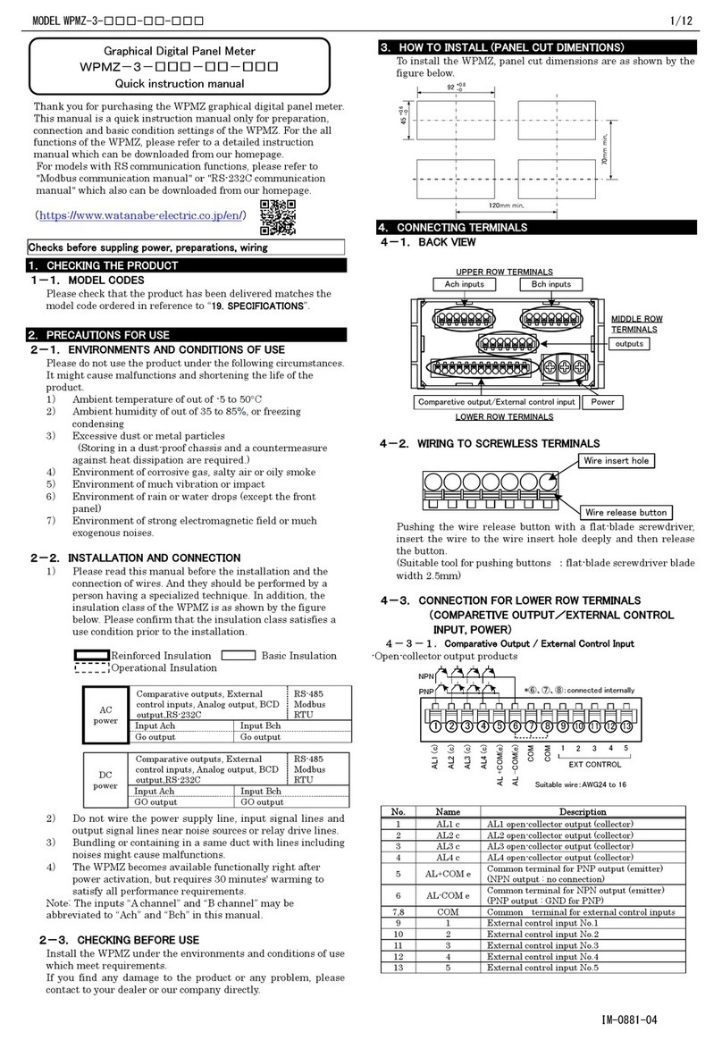
WATANABE A5000 Series User manual

A5000 Series
Users Manual
a
Watanabe Electric Industry Co., Ltd.
UW-48240c

2/72
Contents
Safety Precautions………………………….……………………………………….3
1.Before Using the Product………………………………………………………..4
1.1. Model Codes………………………………………………………………….4
1.2. Checking Each Unit Type and Its Accessories ………………………….5
1.3. Check Before Use……………………………………………………………5
2. About Assembly…………………………………………………………………. 6
2.1. Method Assembly……………………………………………………………6
3. Block Diagram……………………………………………………….……………7
4. Mounting the Product…………………………………………………….……..8
4.1. Mounting the Product to the Panel……………………….………………8
5. Terminal Description and Connection Method…………………….…………9
5.1. Connecting Power……………………………………………………………9
5.2. Connecting Input Signal…………………………………..……………….9
5.3. Connecting External Controls………………………………….………..13
5.4. Connecting Comparison Output……………………….………………..13
5.5. Connecting Analog Output………………………………..…………….. 14
5.6. Connecting Serial Communication………………………..…………….14
6. Components and Their Functions…………………………………..……….15
6.1. Multi Display Unit………………………………………….…………….15
6.2. Single Display Unit…………………………………………….…………16
7. Parameter Setup…………………………………………………….…………17
7.1.Parameter Group………………………………………………….……….17
7.2.LED Display Method………………………………………………………17
7.3.Each Unit and Unit Number………………………………….………….17
7.4. Data lists and Default Settings…………………………………………18
7.5. Differences Between Display Units…………………………………….19
7.6.Operation Flow……………………………………………………………. 20
7.7. Condition Data……………………………………………………………..21
Peak Hold………………………………………………………………….21
Measurement Range………………………………..…………………..22
Number of Averaging Times………………………………………..….24
Number of Moving Averaging Times……………………….…………25
Step Wide……………………………………………………….………...26
Display Blank……………………………………………………….……27
Baud Rate(RS232C/RS485)……………………………………………28
Data Length(RS232C/RS485)………..………………………………. 29
Parity Bit(RS232C/RS485)……………………………………………..30
Stop Bid(RS232C/RS485)………………………………..…………….31
Delimiter(RS232C/RS485)…………………………..………………..32
Equipment ID(RS485)……………………………..………………….33
Analog Output Type……………………………………..…………….34
Digital Zero Back up……………………………….………………….35
Linearization Function………………………….……………………36
Input Selection(input board 15)…………………….……………….37
Tracking Zero Time…………………………………….………………38
Tracking Zero Width…………………………………….…………….39
Sensor Power(input board 17)………………………….…………….40
Power –ON Delay Time………………………………….…………….41
Protect Function…………………………………………….………….42
Unit Number Display……………………………………….………….43
7.8. Comparator Data………………………………………………….………..44
7.9. Scaling Data…………………………………………………….………..46
7.10. Linearization Data…………………………………………..…………51
7.11. Calibration Data………………………………………………..………52
8. Other Functions……………………………………………………..………..54
8.1. The Display Shift Function………………………………….…………54
8.2. Monitor Mode………………………………………….…………………54
9. Control Functions………………………………………………….………….55
9.1. About Control Function…………………………………………….……55
3/72
9.2. Hold Function…………………………………………………..…………55
9.3. Digital Zero Function……………………………………………..……..55
9.4. Peak Hold Function………………………………………..…………….56
10. Output Functions……………………………………………..……………..56
10.1. Comparison Output Function………………………..……………….56
10.2. Analog Output Function………………………………..……………..56
10.3. RS-485 Interface Function…………………………………..………..56
10.4. RS-232C Interface Function………………………………..…………56
11. Error Messages……………………………………………………..………..57
12. Specifications and External Dimensions………………………..……….58
12.1. Input Specifications………………………………………….…………58
12.2. Common Specifications……………………………………..………….62
12.3. Output Specifications………………………………………..…………63
12.4. External Dimensions…………………………………………..……….64
13.Detailed Communications Specifications………………………..……….65
13.1. Terminal Assignments and Connection Method……………………65
13.2. Communication Function Parameters……………………………….65
13.3. RS-485 Transmission/Reception Formats………………..…………65
13.4. Communication Commands………………………………..………….67
14. Warranty and After-service……………………………………..………….72
14.1. Warranty ……………………………………………………..…………..72
14.2. After-service…………………………………………………..………….72
Safety Precautions
(1) Do not apply a voltage or current exceeding the maximum allowable
value; otherwise, it may damage the equipment.
(2) Use a power voltage within the operation range; otherwise, it may result
in a fire, electrical shock, or malfunction.
(3) The contents of this manual are subject to change without notice.
(4)
Although the contents of this manual have been prepared with extra
care, if you have any questions, or find errors or missing information,
contact the sales agent from which you purchased the product or
.
After reading this manual thoroughly, keep it in a convenient place for
future reference.
(5)
Caution
!

1 Before Using the Product
1.1 Model Codes

1.2 Checking Each Unit Type and Its Accessories
1.3 Check Before Use

2 About Assembly
2.1 Assembly Method

3 Block Diagram
POWER
POWER
Input
circuit
A/D
Photo
coupler
RS-232C driver
or
RS-485 driver
Analog
output
circuit
HOLD
DZ
P/H
COM
Relay
Relay
Relay
Photo
coupler
microcomputer
9999
LO-b
LO-c
LO-a
GO-c
GO-c
HI-b
HI-c
HI-a
V-OUT
A-OUT
COM
RXD(+)
TXD(-)
SG
HI
LO
Input unit
Display unit
Output unit
Power unit
※Note that an input unit’s connector and input circuit vary depending on the input unit to be installed.
Power
circuit
Power
circuit

4 Mounting the Product
4.1 Mounting the Product to the Panel
4.1.1
Panel Cut Size
4.1.2 How to Mount the Unit on the Panel
(1) The recommended panel thickness is 0.8 to 5mm. The tightening torque should be approximately
0.39 to 0.49N・m(4 to 5kgf・ cm). .
(2) Do not install the instrument in locations exposed to direct sunligth, an environment where the
ambient temperature goes beyond the range of 0 to 50℃ or the ambient humidity goes beyond the
range of 35 to 85? , or places where dew condensation is formed due to rapid temperature changes.
(3) Do not install the unit where it is exposed to dust, particles, chemicals harmful to electric components,
corrosive gases, etc.
(4)
Do not install the unit where it is exposed to excessive vibration or shock.
(5)
Install the unit horizontally; otherwise, ventilation will be adversely affected and may result in
deterioration.
(6)
When this unit is installed inside other equipment, pay attention to the heat radiation and keep the
heat inside the equiqment 50℃ or below.
Caution
!

5 Terminal Description and Connection Method
External
control
Power
connector
Input (the shape depends on the unit.)
Co
mparison
output
Serial
communication Analog output
6 7 8 9 10 11
12 13 14 15 16 17 18 19
20
21
22
23
24 25 26
5.1 Connecting Power
No. Name
Description
10 POWER
Power terminal without polarity for both
DC and AC
11 POWER
Power terminal without polarity for both
DC and AC
10 11
5.2 Connecting Input Signal
5.2.1 DC Voltage Measuring Unit (Range 11)
1 2 3
Name
Description
1 HI
Positive input terminal
2 NC
Do not connect this terminal.
3 LO
No.
Negative input terminal

5.2.2 DC Voltage Measuring Unit (Range 12 to 15)
Name Description
1 12 Positive input terminal for range 12
(±999.9 mV)
2 13
3 14
No.
1 2 3 4 5
4 15
5 LO Negative input terminal
Positive input terminal for range 13
(±9.999 V)
Positive input terminal for range 14
(±99.99 V)
Positive input terminal for range 15 (±600
V)
5.2.3 DC Current Measuring Unit
1 2 3 4 5
Name Description
1 23 Positive input terminal for range 23
(±9.999 mA)
2 24
3 25
No.
4
LO
5
Negative input terminal
Positive input terminal for range 24
(±99.99 mA)
Positive input terminal for range 25
(±999.9 mA)
5.2.4 AC Voltage Measuring Unit (Ranges 11 to 13)
1 2 3
Name
Description
1 11-12
Positive input terminal for ranges 11
(99.99 mV) and 12
(999.9 mV)
2 13
3
No.
LO
Positive input terminal for range 13 (9.999
V)
Common input terminal
5.2.5 AC Voltage Measuring Unit (Ranges 14 and 15)
1 2 3
Name
Description
1 14
Positive input terminal for range 14 (99.99
V)
2 15
3
No.
LO
Positive input terminal for range 15 (600
V)
Common input terminal

5.2.6 AC Current Measuring Unit (Ranges 23 to 25)
1 2 3 4 5
Name Description
1 23 Positive input terminal for range 23 (9.999
mA)
2 24
3 25
No.
4
LO
5
Negative input terminal
Positive input terminal for range 24 (99.99
mA)
Positive input terminal for range 25 (999.9
mA)
5.2.7 AC Current Measuring Unit (Range 26)
5.8 mm
or less
5.8 mm
or less
Applicable solderless terminals
1 2
Name
Description
No.
1 HI Input terminal
2 LO Input terminal
5.2.8 Resistance Measuring Unit
1 2 3 4 5
Name Description
1 HI Input terminal for all ranges
2 LO
3 +S
No.
4
LO5 Common terminal (grounding terminal for
input circuit)
Input terminal for all ranges
Constant current for four-wire resistance
measurement(positive)
-S Constant current for four-wire resistance
measurement(negative)

5.2.9 Temperature Measuring Unit (TC)
1 2 3
Name
Description
1 +
Positive terminal for thermocouple
2 NC
3
No.
-
Do not connect this terminal.
Negative terminal for thermocouple
5.2.10 Temperature Measuring Unit (RTD)
Connection of three-wire sensor
1 2 3
Name Description
1 A Resistance sensor wire
2 B
3
No.
C Elimination of wire resistance
Resistance sensor wire
The analog output at the time of a burnout becomes + side
at the time of A or B disconnection, and is set to 0V or 1V,
and 4mA at the time of C disconnection.
When A or B is disconnection, it is displayed as OL, and when
C is disconnection, it is displayed as ----.
5.2.11 Frequency Measuring Unit (Open collector, logic, and magnet)
1 2 3 4 5
Name Description
1 HI Positive input terminal
2 LO
3 +15V
No.
4
COM5 Common terminal (grounding terminal for
input circuit)
Negative input terminal
Power output for sensor (positive)
0V Power output for sensor (negative)
5.2.12 Frequency Measuring Unit (AC voltage 500 Vrms max.)
1 2 3
Name Description
1 HI Input terminal
2 NC
3
No.
LO
Do not connect this terminal.
Input terminal

5.2.13 Strain Gauge Input Unit (Load cell)
1 2 3 4 5
Name Description
1 +SIG Positive input terminal
2 -SIG
3 +EXC
No.
4
COM5 Common terminal (grounding terminal for
input circuit)
Negative input terminal
Power output for sensor (positive)
-EXC Power output for sensor (negative)
5.2.14 Process Input Measuring Unit
1 2 3
Name Description
1 V-IN Positive input terminal for 1 to 5 V range
2 A-IN
3
No.
LO
Positive input terminal for 4 to 20 mA range
Negative input terminal
5.3 Connecting External Controls
Name
Description
6 HOLD
Control for hold function. Enabled when
short
-
circuited or at the same potential as
COM.
7 DZ
Control for digital zero function. Enabled
when short
-
circuited or at the same
potential as COM.
6 7 8 9
8
9
PH
COM
No.
Control for peak hold function. Enabled
when short
-
circuited or at the same
potential as COM.
Common for all external control terminals.
5.4 Connecting Comparison Output
12 13 14 15 16 17 18 19
Name Description
12 LO-b LO output terminal (b contact)
13 LO-c
14
No.
LO-a
Common terminal for LO output
LO output terminal (a contact)
15 GO-c Common terminal for GO output
16 GO-a
17 HI-b
GO output terminal (a contact)
HI output terminal (b contact)
18 HI-c
19 HI-a
Common terminal for HI output
HI output terminal (a contact)

5.5 Connecting Analog Output
24 25 26
Name Description
24 COM Common terminal for analog output
25 A-OUT
26
No.
V-OUT
Current output terminal (4 to 20 mA)
Voltage output terminal (1 to 5 V, 0 to 1 V,
and 0 to 10 V)
5.6 Connecting Serial Communication
20212223 Name Description
20 RXD(+) RS-232C: transmission;
RS-485: Non-reverse output
21 TXD(-)
22
No.
NC
RS-232C: reception;
RS-485: Reverse output
Do not connect this terminal.
23 SG Common terminal for communications

6 Components and Their Functions
6.1 Multi Display
Mode key(7)
Pressing the Mode and Enter keys
together changes to the parameter
setting mode.
Selects the item to be set.
Pressing the Mode and Shift keys
together changes to the shift function
setup mode.
Pressing the Mode and Incremental
keys together turns on/off the “Digital
zero” indicator.
(8) Shift key
Pressing the Shift and Enter keys
together changes to the parameter
checking mode. (Comparator data can
be set.)
Pressing the Shift and Mode keys
together changes to the shift function
setup mode.
Selects from items in the maximum/
minimum/(maximum-minimum)/input
value monitoring mode. (Hold down the
key for about one second.)
Changes the digit to be set.
Increment key(9)
Pressing the Increment and Mode keys
together turns on/off the “Digital
zero” indicator.
Pressing the Increment and Enter keys
changes to the maximum/minimum/
(maximum-minimum)/input value
monitoring mode.
Resets the maximum/minimum/
(maximum-minimum)/input value
monitoring mode. (Hold down the key
for about one second.)
Changes the value or content
of a selected digit.
(Increments the value)
(1)
(2)
(3)
(4)
(6) (7) (8) (9)
(5)
No. Name Main Functions
During measurement During parameter setup
(1) Main display Indicates the measured value. IIndicates information on the
parameter to be set.
Judgment
indicators
HI
(2) GO
LO
Indicates the result of judgment and
turns on if the measured value > HI
judgment value.
Indicates the result of judgment and
turns on if LO judgment value ≦ the
measured value ≦ HI judgment value.
Indicates the result of judgment and
turns on if the measured value < LO
judgment value.
(3) Function
indicators
ME Turns on if “digital zero backup” is on.
PH Turns on if “peak hold/valley hold/
peak - valley hold” is on.
Turns on if “digital zero” is on.DZ
RE
Turns on if remote control is being
performed through RS-232C or RS-
485 interface.
(4) Sub-display 1
Indicates the HI side judgment value.
Indicates the item in the maximum/
minimum/(maximum-minimum)/input
value monitoring mode.
Indicates the LO side judgment value.
Sub-display 2(5) Indicates information on the item in
the maximum/minimum/(maximum-
minimum)/input value monitoring mode.
Indicates the item to be set.
(6) Enter key
Pressing the Enter and Mode keys
together changes to the parameter
setting mode.
Pressing the Enter and Increment keys
together changes to the maximum/
minimum/(maximum-minimum)/input
value monitoring mode.
Switches from the maximum/
minimum/(maximum-maximum/
minimum/(maximum-minimum)/input
value monitoring mode to the
comparative judgment reading mode.
Returns to the measurement
mode.

6.2 Single Display
(3)
No. Name Main Functions
During measurement During parameter setup
(1) Main display
Indicates the measured value. IIndicates information on the
parameter to be set.
Indicates information on the item in
the maximum/minimum/(maximum-
minimum)/input value monitoring mode.
Judgment
indicators
HI
(2) GO
LO
Indicates the result of judgment and
turns on if the measured value > HI
judgment value.
Indicates the result of judgment and
turns on if LO judgment value ≦ the
measured value ≦ HI judgment value.
Indicates the result of judgment and
turns on if the measured value < LO
judgment value.
(3) Function
indicators ME Turns on if “digital zero backup” is on.
PH Turns on if “peak hold/valley hold/
peak - valley hold” is on.
Turns on if “digital zero” is on.
DZ
RE
Turns on if remote control is being
performed through RS-232C or RS-
485 interface.
Flashes when linearization data output
values are set.
Flashes when linearization data input
values are set.
(6) Enter key
Pressing the Mode and Enter keys
together changes to the parameter
setting mode.
Pressing the Enter and Increment keys
together changes to the maximum/
minimum/(maximum-minimum)/input
value monitoring mode.
Switches from the maximum/
minimum/(maximum-maximum/
minimum/(maximum-minimum)/input
value monitoring mode to the
comparative judgment reading mode.
Returns to the measurement
mode.
Mode key(7)
Pressing the Mode and Enter keys
together changes to the parameter
setting mode.
Selects the item to be set.
Pressing the Mode and Shift keys
together changes to the shift function
setup mode.
Pressing the Mode and Incremental
keys together turns on/off the “Digital
zero” indicator.
(1)(2)
(6) (7) (8) (9)
(8) Shift key
Pressing the Shift and Enter keys
together changes to the parameter
checking mode. (Comparator data can
be set.)
Pressing the Shift and Mode keys
together changes to the shift function
setup mode.
Selects from items in the maximum/
minimum/(maximum-minimum)/input
value monitoring mode. (Hold down the
key for about one second.)
Changes the digit to be set.
Holding down the Shift key for about
one second moves to the HI judgment
value indicator.
Increment key(9)
Pressing the Increment and Mode keys
together turns on/off the “Digital
zero” indicator.
Pressing the Increment and Enter keys
changes to the maximum/minimum/
(maximum-minimum)/input value
monitoring mode.
Resets the maximum/minimum/
(maximum-minimum)/input value
monitoring mode. (Hold down the key
for about one second.)
Changes the value or content
of a selected digit.
(Increments the value)
Holding down the Increment key for
about one second moves to the LO
judgment value indicator.

7 Parameter Setup
7.1 Parameter Group
A group of parameters concerning the linearize (linearity
correction) function.
Description
A droup of parameters for setting the correlations between input
signals and a displays, the correlations between displays and
analog outputs etc.
A group of parameters concerning comparison operations such
as HI/LO comparison judgment value and hysteresis.
A group of the parameters concerning basic operations (such as
measurement range power supply frequency, and sampling
speed) and the operations of special functions and optional
functions.
A group of parameters concerning sensor calibrations when
strain gauge input units are mounted.
Group name
Condition data
Comparator data
Scaling data
Linearize data
Calibration data
7.2 LED Display Method
0 1 2 3 4 5 6 7 8 9 -
A B C D E F G H I J K L M
N O P Q R S T U V W X Y Z
7.3 Each Unit and Unit Number
NO.
01
02
03
04
05
06
07
08
09
10
11
12
13
14
15
16
17
18
Frequency measuring unit (Open collector,logic and magnet)
AC voltage measuring unit (Average rms range 11 to 13)
Description
DC current measuring unit (range 23 to 25)
DC voltage measuring unit (range 12 to 15)
DC voltage measuring unit (range 11)
AC voltage measuring unit (Average rms range 14,15)
AC voltage measuring unit (True rms range 11 to 13)
AC voltage measuring unit (True rms range 14,15)
AC current measuring unit (Average rms range 23 to 25)
AC current measuring unit (Average rms range 26)
AC current measuring unit (True rms range 23 to 25)
AC current measuring unit (True rms range 26)
Resistance measuring unit
Temperature measuring unit (TC)
Temperature measuring unit (RTD)
Frequency measuring unit (50 to 500Vrms)
Strain gauge input unit
Process input unit (4 to 20mA, 1 to 5V)
Input unit Output unit
NO.
0
1
2
3
4
5
6
7
Comparison output and analog output
Comparison output, analog output and RS-232C
Comparison output, analog output and RS-485
RS-232C
Description
Analog output
Comparison output
None
RS-485

7.4 Data Lists and Default Settings
Default
Equipped
Indication
Name
value
as
01
02
03
04
05
06
07
08
09
10
11
12
13
14
15
16
17
18
0
1
2
3
4
5
6
7
PVH
Peak hold setup
PH
○
RANG
Measurement range setup
*1
×
○
○
○
○
○
○
○
×
○
×
○
○
○
○
○
×
○
11
15
25
13
15
13
15
25
26
25
26
14
B
JPB
14
14
2A
AVG
Number of averaging
1
○
○
○
○
○
○
○
○
○
○
○
○
○
○
×
×
○
○
MAV
Number of moving averaging setup
OFF
○
S.UD
Step wide setup
1
○
BLNK
Indication blank setup
OFF
○
UNIT
Unit setup
C
×
×
×
×
×
×
×
×
×
×
×
×
○
○
×
×
×
×
BAUD
Baud rate setup
9600
×
×
×
○
○
×
○
○
DATA
Data length setup
7
×
×
×
○
○
×
○
○
P.BIT
Parity bit setup
E
×
×
×
○
○
×
○
○
S.BIT
Stop bit setup
2
×
×
×
○
○
×
○
○
T-
Delimiter setup
CR.LF
×
×
×
○
○
×
○
○
ADR
Equipment ID setup
00
×
×
×
×
○
×
×
○
A.OUT
Analog output setup
OFF
×
×
○
×
×
○
○
○
B.UP
Digital zero backup setup
OFF
○
LINE
Linearization setup
CLR
○
I.SEL
Input selection
OC
×
×
×
×
×
×
×
×
×
×
×
×
×
×
○
×
×
×
TR T
Tracking zeroing time setup
00
○
×
×
TR V
Tracking zeroing width setup *2
01
○
×
×
SNSR
Sensor power setup
10
×
×
×
×
×
×
×
×
×
×
×
×
×
×
×
×
○
×
P
ON
Power-on delay setup
OFF
○
PRO
Protect setup
OFF
○
U-NO.
Unit number Indication setup
ON
○
S-HI
HI side judgment value setup
1000
×
○
×
×
×
○
○
○
S-LO
LO side judgment value setup
500
×
○
×
×
×
○
○
○
H-HI
HI side hysteresis setup
0
×
○
×
×
×
○
○
○
H-LO
LO side hysteresis setup
0
×
○
×
×
×
○
○
○
FSC
Full scale Indication value setup
*1
○
○
○
○
○
○
○
○
○
○
○
○
×
×
×
×
×
○
9999
9999
9999
9999
9999
9999
9999
9999
9999
9999
9999
9999
9999
FIN
Full scale input value setup
*1
○
○
○
○
○
○
○
○
○
○
○
○
×
×
×
×
×
○
9999
9999
9999
9999
9999
9999
9999
9999
5000
9999
5000
9999
*3
OFS
Offset indication value setup
*1
○
○
○
○
○
○
○
○
○
○
○
○
×
×
×
×
×
○
0
0
0
0
0
0
0
0
0
0
0
0
0
OIN
Offset input value setup
*1
○
○
○
○
○
○
○
○
○
○
○
○
×
×
×
×
×
○
0
0
0
0
0
0
0
0
0
0
0
0
*4
PS
Pre-scaling value setup
1
×
×
×
×
×
×
×
×
×
×
×
×
×
×
○
○
×
×
PPR
Frequency division setup
1
×
×
×
×
×
×
×
×
×
×
×
×
×
×
○
○
×
×
DLHI
Digital limiter HI value setup
9999
○
×
×
×
×
×
×
×
×
DLLO
Digital limiter LO value setup
-9999
○
×
×
×
×
×
×
×
×
AOHI
Analog output HI indication setup
9999
×
×
○
×
×
○
○
○
AOLO
Analog output LO indication setup
0
×
×
○
×
×
○
○
○
DEP
Decimal point position setup
None
○
*5
○
ZERO
Zero input value *6
0
×
×
×
×
×
×
×
×
×
×
×
×
×
×
×
×
○
×
SPIN
Span input value *6
2000
×
×
×
×
×
×
×
×
×
×
×
×
×
×
×
×
○
×
SPAN
Span indication
9000
×
×
×
×
×
×
×
×
×
×
×
×
×
×
×
×
○
×
SHF
Shift data setup
0
○
*1
Each value in the lower part of a cell in the columns on the right is the default value.
*2
Tracking zero width setup parameter is not indicated if the tracking time is set to OFF(0).
*3
5000 for 1 V range and 2000 for 2 A range
*4
1000 for 1 V range and 400 for 2 A range
*5
Linearization data are not set up for the default values.
*6
This value is not indicated if calibration is done using an actual load.
The shaded parts show the parameters that must be set for each unit.
Shift data
Input unit number Output unit number
Linearization data
Calibration data
Condition data
Comparator data
Scaling data

7.5 Differences Between Display Units
7.5.1 Single Display Unit
Setup contents and parameter name
7.5.2 Multi Display Unit
Setup contents Parameter name

7.6 Operation Flow
Condition data Comparator data Scaling data Linearization data
Measurement
Pressing the ENTER key saves the data and returns to the measurement mode.
Calibration data
(Data are backed up with EEPROM even when the power is turned off.)
Other manuals for A5000 Series
1
Table of contents
Other WATANABE Measuring Instrument manuals

WATANABE
WATANABE WPMZ-5 User manual

WATANABE
WATANABE WPMZ-3 Series User manual

WATANABE
WATANABE WPMZ Series User manual

WATANABE
WATANABE A5000 Series User manual

WATANABE
WATANABE A9000 Series User manual

WATANABE
WATANABE WPMZ-3 Series User manual

WATANABE
WATANABE WPMZ-1 User manual

WATANABE
WATANABE WPMZ Series Use and care manual
Popular Measuring Instrument manuals by other brands

BURG WATCHER
BURG WATCHER ProfiScale PRECISE PS 7215 operating instructions

PERSENTECH
PERSENTECH OttoView-CD User Manual and Instruction Guide

Raytech
Raytech SynchroKing 4S Mk2 instruction manual

SYC
SYC HT-4616 user manual

Graco
Graco PPM 3050H Instructions-parts list

Ebtron
Ebtron Advantage IV Series Operation & maintenance manual