manuals.online logo
Brands
  1. Home
  2. •
  3. Brands
  4. •
  5. Watchguard
  6. •
  7. Firewall
  8. •
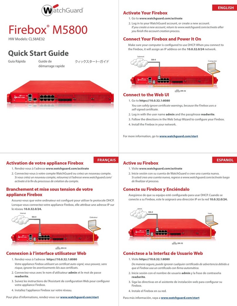
  9. Watchguard Firebox M5800 Installation instructions

Watchguard Firebox M5800 Installation instructions

Other manuals for Firebox M5800

1

Other Watchguard Firewall manuals

Watchguard SOHO User manual

Watchguard

Watchguard SOHO User manual

Watchguard XTM 5 Series User manual

Watchguard

Watchguard XTM 5 Series User manual

Watchguard Firebox t10 Instruction Manual

Watchguard

Watchguard Firebox t10 Instruction Manual

Watchguard Firebox T85 User manual

Watchguard

Watchguard Firebox T85 User manual

Watchguard Firebox T45 User manual

Watchguard

Watchguard Firebox T45 User manual

Watchguard XTM 1520-RP User manual

Watchguard

Watchguard XTM 1520-RP User manual

Watchguard Firebox M4800 Installation instructions

Watchguard

Watchguard Firebox M4800 Installation instructions

Watchguard Firebox M4600 Installation instructions

Watchguard

Watchguard Firebox M4600 Installation instructions

Watchguard Firebox M440 User manual

Watchguard

Watchguard Firebox M440 User manual

Watchguard Firebox V10 Manual

Watchguard

Watchguard Firebox V10 Manual

Watchguard Firebox T30 User manual

Watchguard

Watchguard Firebox T30 User manual

Watchguard Firebox SOHO 6.1 User manual

Watchguard

Watchguard Firebox SOHO 6.1 User manual

Watchguard Firebox Vclass User manual

Watchguard

Watchguard Firebox Vclass User manual

Watchguard Firebox t10 User manual

Watchguard

Watchguard Firebox t10 User manual

Watchguard Firebox V60 Installation and operating instructions

Watchguard

Watchguard Firebox V60 Installation and operating instructions

Watchguard Firebox T10-D User manual

Watchguard

Watchguard Firebox T10-D User manual

Watchguard Firebox M5800 User manual

Watchguard

Watchguard Firebox M5800 User manual

Watchguard Firebox T35 User manual

Watchguard

Watchguard Firebox T35 User manual

Watchguard XCS Series Installation instructions

Watchguard

Watchguard XCS Series Installation instructions

Watchguard Firebox T35 Series Installation instructions

Watchguard

Watchguard Firebox T35 Series Installation instructions

Watchguard AP300 User manual

Watchguard

Watchguard AP300 User manual

Watchguard XTM 1050 User manual

Watchguard

Watchguard XTM 1050 User manual

Watchguard Firebox SOHO 6 Wireless User manual

Watchguard

Watchguard Firebox SOHO 6 Wireless User manual

Watchguard Firebox SOHO 6 Wireless User manual

Watchguard

Watchguard Firebox SOHO 6 Wireless User manual

Popular Firewall manuals by other brands

Fortinet FSM-500F Configuration guide

Fortinet

Fortinet FSM-500F Configuration guide

Cisco Meraki MX100 installation guide

Cisco

Cisco Meraki MX100 installation guide

Cisco S190 quick start guide

Cisco

Cisco S190 quick start guide

Fortinet FortiGate Voice Series install guide

Fortinet

Fortinet FortiGate Voice Series install guide

SecureLogix ETM System installation guide

SecureLogix

SecureLogix ETM System installation guide

Huawei USG6000 Series Upgrade guide

Huawei

Huawei USG6000 Series Upgrade guide

NETGEAR ProSafe FVX538 Reference manual

NETGEAR

NETGEAR ProSafe FVX538 Reference manual

Lanner FW-8877 user manual

Lanner

Lanner FW-8877 user manual

Nexcom DNA 1150 user manual

Nexcom

Nexcom DNA 1150 user manual

Cisco 3110 Hardware installation guide

Cisco

Cisco 3110 Hardware installation guide

Fortinet FortiGate-60 series install guide

Fortinet

Fortinet FortiGate-60 series install guide

ADTRAN NetVanta 2300 Specifications

ADTRAN

ADTRAN NetVanta 2300 Specifications

Swisscom Internet Backup manual

Swisscom

Swisscom Internet Backup manual

SonicWALL NSa 5700 quick start guide

SonicWALL

SonicWALL NSa 5700 quick start guide

DPtech FW1000 SERIES Maintenance manual

DPtech

DPtech FW1000 SERIES Maintenance manual

FEITIAN MultiPass FIDO product manual

FEITIAN

FEITIAN MultiPass FIDO product manual

Trend Micro Deep Edge quick start guide

Trend Micro

Trend Micro Deep Edge quick start guide

Smoothwall S10 Appliance Getting started guide

Smoothwall

Smoothwall S10 Appliance Getting started guide

manuals.online logo
manuals.online logoBrands
  • About & Mission
  • Contact us
  • Privacy Policy
  • Terms and Conditions

Copyright 2025 Manuals.Online. All Rights Reserved.

2.2.2021 Firebox M5800 Hardware Guide
https://www.watchguard.com/help/docs/help-center/en-US/Content/en-US/Hardware-Guides/firebox-m5800-hardware-guide.html 1/18
Firebox M5800 Hardware Guide
WatchGuard security appliances deliver unparalleled unified threat management, superior performance,
ease of use, and value. Powerful subscription-based security services deliver in-depth defenses against
advanced malware, ransomware, botnets, trojans, viruses, drive-by downloads, phishing and much more.
This guide introduces the Firebox M5800, a RoHS-compliant (lead-free) hardware product offered by
WatchGuard. The Firebox M5800 consolidates critical network and security functions into a single,
centrally managed device, and is ideal as the ‘hub’ for distributed, hub-and-spoke type deployment
scenarios.
Fireware OS
The Firebox M5800 device uses WatchGuard’s next generation UTM OS — Fireware OS. Each Firebox
M5800 device includes Fireware OS and delivers exceptional protection against today's sophisticated
threats to make sure that your business stays connected. For more information on the features of
Fireware OS, see Fireware Help.
About Your Hardware
Hardware Specifications
This table shows the hardware specifications for the WatchGuard Firebox M5800.
Processor Intel Cascade Lake Xeon 6230
Storage 512 GB Solid State HDD
Memory: DDR4 32 GB
Power Supply Dual power supplies
400W
100-240VAC/6-3A/47-63Hz
Dimensions D = 58 cm (22.83")
W = 43.8 cm (17.25")
H = 4.4 cm(1.73")
Weight 12 kg (26.45 lbs)
Interface Specifications
2.2.2021 Firebox M5800 Hardware Guide
https://www.watchguard.com/help/docs/help-center/en-US/Content/en-US/Hardware-Guides/firebox-m5800-hardware-guide.html 2/18
This table shows the interface specifications for the WatchGuard M5800 as shipped.
Management Interface 1x 1000 Base TX (10/100/1000Mbps), RJ45 connector
Network Interfaces 8x 1000 Base TX (10/100/1000Mbps), RJ45 connector
4x 10 G SFP+ ports
I/O Interfaces 2 USB 3.0
1 RJ45 RS232 console port
The Firebox also has two slots where you can install additional interface modules. The supported
interface modules are described in the Hardware Description section.
Environmental Requirements
To safely install your Firebox, we recommend that you:
Install it in a network rack.
Put it in a secure area, such as a locked room, to block the device from people who do not have
permission to use it.
Connect it to a conditioned power supply to prevent damage from sudden power changes.
This table shows other environmental requirements for the M5800 appliance.
Operating Temperature 0° to 40°C (32° to 104°F)
Operating Humidity 5% to 90% non-condensing
Non-operating Temperature –10° to 70°C (14° to 158°F)
Non-operating Humidity 5% to 90%, non-condensing
Hardware Description
Front
Front view of the Firebox:
Left front panel detail:
2.2.2021 Firebox M5800 Hardware Guide
https://www.watchguard.com/help/docs/help-center/en-US/Content/en-US/Hardware-Guides/firebox-m5800-hardware-guide.html 3/18
Buttons and Indicators
Power ( )
The power indicator is green when the device is powered on.
Arm/Disarm ( )
When the device is armed and ready to pass traffic, this indicator is green. When the device is
powered on, but not ready to pass traffic, this indicator is red.
Storage ( )
When there is activity on the internal storage, this indicator is yellow.
Power Button ( )
The Power button is lit to indicate power status. It is green when the Firebox is powered on, and
red when power is available, but the Firebox is powered off.
When the Power button is red, press it to power on the Firebox.
When the Power button is green, press and hold the power button for five seconds to power off
the Firebox. The Firebox does not power off if you briefly press the Power button.
Reset Button
The Reset button, located to the left of the USBinterfaces, resets the device to factory-default
settings. To reset the device, see Restore Factory Default Settings
Built-in Interfaces
The Firebox M5800 has a management interface, two USB interfaces, and one serial console port. It also
includes two pre-installed interface modules, as described in the subsequent section.
Dual USB interfaces
The device includes two USB interfaces. Connect a USB storage device for USB backup and restore,
or to store a support snapshot. For more information, see Fireware Help.
Console port
An RJ45 connector for the serial (console) interface is located above the USB interfaces. You can
connect to this serial interface to log in to the Fireware Command Line Interface.
For more information about the command line interface, see the current
Command Line Interface
Reference
available on the Firebox documentation page at https://www.watchguard.com/wgrd-
help/documentation/xtm.
Management interface
The management interface, labeled or Mgmt, is an RJ45 Ethernet interface located to the
right of the USB interfaces. You must connect to this interface to configure the Firebox when it
starts with factory-default settings. The management interface is interface 32.
Interface Modules
The Firebox M5800 has four interface module slots, A, B, C, and D. Slots A and B have modules pre-
installed.
2.2.2021 Firebox M5800 Hardware Guide
https://www.watchguard.com/help/docs/help-center/en-US/Content/en-US/Hardware-Guides/firebox-m5800-hardware-guide.html 4/18
Slot A has the 8 Port 1G RJ45 Copper Module preinstalled
Slot B has the 4 Port 10Gbps SFP+ Fiber Module preinstalled
To add more interfaces to your Firebox, you can install interface modules in slots C and D. You must
install the interface module before you can configure the interfaces. For instructions to install or remove
interface modules, see “Interface Module Installation” on page 21.
Interface modules are not hot-swappable. To avoid damage to the system, power off
the Firebox before you install or remove interface modules.
You can purchase these compatible interface modules from an authorized WatchGuard reseller:
WatchGuard Firebox M 8 Port 1 Gb Copper Module — WatchGuard SKU WG8592
WatchGuard Firebox M 8 Port SFP Fiber Module — WatchGuard SKU WG8593
WatchGuard Firebox M 4 Port 10 Gb SFP+ Fiber Module — WatchGuard SKU WG8594
WatchGuard Firebox M 2 Port 40 Gb QSFP+ Fiber Module — WatchGuard SKU WG8023
For each interface module, ports are numbered from 0-7, 0-3, or 0-1. The interface numbers that appear
in the Firebox configuration depend on the number of ports on the interface module, and the interface
module slot where the interface module is installed.
A 8 A0-A7 0-7 (preinstalled)
4 A0-A3 0-3
2 A0-A1 0-1
B 8 B0-B7 8-15
4 B0-B3 8-11 (preinstalled)
2 B0-B1 8-9
C 8 C0-C7 16-23
4 C0-C3 16-19
2 C0-C1 16-17
D 8 D0-D7 24-31
4 D0-D3 24-27
2 D0-D1 24-25
Indicators for the modular interfaces are described below.
8 Port 1G RJ45 Interface Module
8 Port 1G SFP Interface Module
4 Port 10G SFP+ Interface Module
2 Port 40Gb QSFP+ Fiber Module
Installed in
slot
Number of
Ports
Modular Interface Port
Numbers
Interface Numbers in Management
Software
2.2.2021 Firebox M5800 Hardware Guide
https://www.watchguard.com/help/docs/help-center/en-US/Content/en-US/Hardware-Guides/firebox-m5800-hardware-guide.html 5/18
For a list of compatible transceivers, see Supported transceivers for Firebox and
XTMAppliances in the WatchGuard Knowledge Base.
Rear
Rear view of the Firebox:
Cooling fans
The fans decrease the internal temperature of the device. When you connect the Firebox to power,
the fans start at a low speed. When you power on the Firebox, the fan speed increases to
maximum RPM. The device adjusts the fan speed based on the external temperature, CPU load,
and power supply load.
When the Firebox is powered off, power supply fans continue to run at a lower RPM
while the Firebox is connected to power.
If a power supply fails or is not connected to power, the other power supply has a
higher load, and the power supply fan is louder.
Power switch
Controls the power supplied to the Firebox. The Power switch activates both power supplies.
AC receptacles
Each AC receptacle accepts a detachable AC power cord supplied with the Firebox. Each power
supply is a WatchGuard standard auto-sensing AC power supply.
Replaceable power supplies
There are two power supplies on the Firebox M5800, each with a power indicator at the top.
For instructions to install a replacement power supply, see Power Supply Installation.
Green flashing Power is connected to at least one power supply, device is powered off
Green solid Power is connected, device is powered on
Red flashing Power is not connected or power supply failed, device is powered on
Power Indicator Color Power Supply Status
2.2.2021 Firebox M5800 Hardware Guide
https://www.watchguard.com/help/docs/help-center/en-US/Content/en-US/Hardware-Guides/firebox-m5800-hardware-guide.html 6/18
Not lit Power is not connected, device is powered off
Alarm Reset button
When the Firebox is powered on, if either power supplies fails or is not connected to a power
source, an audible alarm sounds. To silence the alarm, press the alarm reset button, located to the
left of the power supplies. After you silence the alarm, the indicator for the failed power supply
flashes red.
Restore Factory Default Settings
If you ever need to, you can restore your Firebox to its factory-default settings. For example, if you do not
know the administrator account passphrase or you want to start over with a new configuration, you can
reset your device. Make sure you back up your device configuration before you reset your device in case
you want to restore it in the future.
To reset your device:
1. Power off the device.
2. Press and hold the Reset button, while you briefly press the Power button on the front of the
device to power it on.
3. Continue to hold the Reset button while the Arm indicator is red.
4. Continue to hold the Reset button while the Arm indicator slowly flashes green.
5. When the Arm indicator flashes green more rapidly, release the Reset button.
6. Wait until the Arm indicator starts to flash red.
7. Press and hold the Power button on the front of the device for five seconds to power off the
device.
8. Briefly press the Power button on the front of the device to power it on.
Hardware Installation
Your Firebox ships with a rack mount kit. It also supports user-installable components. This document
includes instructions to install your Firebox andits components:
Rack mount installation
Interface module installation
Power supply installation and replacement
Power Indicator Color Power Supply Status
2.2.2021 Firebox M5800 Hardware Guide
https://www.watchguard.com/help/docs/help-center/en-US/Content/en-US/Hardware-Guides/firebox-m5800-hardware-guide.html 7/18
Rack Mount Installation
Each Firebox device ships with rack mount ears for installation in a network rack.
Rack rail kit
2 sliding rails
10 small screws and 8 large screws
Front ear bracket kit
2 front ear brackets
6 small screws and 2 large screws
Precautions
When you install the device in a rack, make sure you consider these factors:
Elevated Operating Ambient Temperature
If you install the device in a closed or multi-unit rack assembly, the operating ambient temperature
of the rack environment might be greater than room ambient. Make sure the ambient
temperature of the rack environment is within the certified operating range specified in this
Hardware Guide.
Reduced Air Flow
2.2.2021 Firebox M5800 Hardware Guide
https://www.watchguard.com/help/docs/help-center/en-US/Content/en-US/Hardware-Guides/firebox-m5800-hardware-guide.html 8/18
When you install the device in a rack, make sure that the amount of air flow required for safe
operation of the equipment is not compromised.
Mechanical Loading
When you mount the device in the rack, avoid hazardous conditions caused by uneven mechanical
loading.
Circuit Overloading
Make sure you connect the device to the power supply circuit in such a way that there is no
overloading of the circuits, and no impact on overcurrent protection and supply wiring.
Reliable Grounding
Make sure all rack-mounted equipment is correctly grounded. For example, make sure you use
power strips instead of direct connections to the branch circuit.
Do not use your slide/rail mounted device as a shelf or work space.
Separate the inner rails from the outer rails
Attach the inner rails and front ear brackets to the Firebox
Attach the outer rails to the rack
Install alternate screws on the rails (if needed)
Install the Firebox in the rack
Remove the Firebox from the rack
Interface Module Installation
You can install two additional interface modules in slots A and B of your Firebox. The supported interface
modules are described in detail in the Interface Modules section.
Interface modules are not hot-swappable. To avoid damage to the system, power
off the Firebox before you install or remove interface modules.
Install an Interface Module
To install an interface module:
1. Disconnect the power cables from the Firebox.
2. Loosen the two captive screws on the slot cover.
3. Remove the slot cover to expose the interface slot.
4. Insert the interface module into the slot, and push it firmly into place.
5. Tighten the two captive screws on the interface module to attach the interface to the Firebox.
6. Reconnect the power cables to the Firebox.
The Firebox starts automatically. When the Firebox starts, Fireware automatically detects all installed interfaces.
Remove an Interface Module
2.2.2021 Firebox M5800 Hardware Guide
https://www.watchguard.com/help/docs/help-center/en-US/Content/en-US/Hardware-Guides/firebox-m5800-hardware-guide.html 9/18
Before you remove an installed interface module, make sure that the interfaces on
that module are not enabled in the Firebox configuration. You cannot manage a
Firebox if an enabled interface has been removed.
To remove an installed interface module:
1. Disconnect the power cables from the Firebox.
2. Disconnect all network cables from the installed interface module.
3. Loosen the two screws on the installed interface module.
4. Slide the interface module out of the slot.
5. Place the removed interface module on an antistatic surface, or immediately install it in another
slot.
6. Install a slot cover over the empty slot or install another interface module. The slot cover keeps
dust out of the Firebox.
Power Supply Installation and Replacement
The Firebox has two redundant hot-swappable power supplies. If a power supply fails, you can replace it
while the Firebox is powered by the other power supply.
To replace a power supply:
1. Use the power indicator to identify the failed power supply. If the device is powered on, the
indicator on the failed power supply flashes red after you reset the audible alarm.
2. Disconnect the power cable from the power supply you want to replace.
3. Find the release tab, located on the left side of the power supply.
4. Firmly push the release tab to the right, while you use the power supply handle to pull the power
supply out of the slot.
5. Slide the replacement power supply into the open slot.
6. Press firmly on the face of the power supply until it is flush with the back of the Firebox. If the
replacement is successful, the power indicator light for the new power supply is green.
You can purchase a replacement power supply from an authorized WatchGuard reseller.
WatchGuard Firebox M5800 Hot Swap Power Supply — WatchGuard SKUWG9013
2.2.2021 Firebox M5800 Hardware Guide
https://www.watchguard.com/help/docs/help-center/en-US/Content/en-US/Hardware-Guides/firebox-m5800-hardware-guide.html 10/18
Notices
All WatchGuard products are designed and tested to meet strict safety requirements. These
requirements include product safety approvals and other global compliance standards. Read these
instructions carefully before you operate the product, and refer to them as needed for continued safe
operation of your product.
Product Safety Certification
The WatchGuard product is safety certified under the following standards:
CAN/CSA C22.2 No.60950-1-07, Second Edition 2014-10
UL 60950-1, Second Edition 2014-10-14
IEC 60950-1, 2005+A1:2009+A2:2013
IEC 62368-1: 2014 2nd edition
EN 60950-1:2006+A11:2009+A1:2010+A12:2011+A2:2013
Safety Warning
Do not place objects on the power cord.
Do not obstruct the ventilation openings. These openings prevent overheating of the machine.
Never push objects of any kind into slots or openings on this equipment. Making a contact with a
voltage point or shorting out a part may result in fire or electrical shock.
When removing or installing an appliance, follow the general installation safety instructions.
You must disconnect the AC power cord from the Firebox before you remove the cover of the
Firebox for any reason.
There is risk of explosion if the battery is replaced by an incorrect type. Dispose of used batteries
according to the manufacturer’s instructions.
警示 本電池如果更換不正確會有爆炸的危險,請勿自行更換電池
Disclaimer
WatchGuard shall not be held liable if the end user alters, modifies, or repairs any WatchGuard hardware
appliance.
Hinweise Zur Sicherheit
Alle WatchGuard Produkte werden entwickelt und getestet, um strenge Sicherheitsanforderungen zu
erfüllen. Diese Anforderungen umfassen Produktsicherheit Zulassungen und andere globale
Compliance-Standards. Bitte lesen Sie die folgenden Anweisungen sorgfältig, bevor Sie das Produkt, und
bezeichnen sie als notwendig, um den sicheren Betrieb des Geräts zu gewährleisten. Weitere
Informationen finden Sie in der elektronischen Hardware Guide.
Die WatchGuard Produkt ist Sicherheit unter den folgenden Normen zertifiziert
CAN/CSA C22.2 No.60950-1-07, Second Edition 2014-10
UL 60950-1, Second Edition 2014-10-14
IEC 60950-1:2005+A1:2009+A2:2013
IEC 62368-1: 2014 2nd edition
EN 60950-1:2006+A11:2009+A1:2010+A12:2011+A2:2013