Watchguard CHG400 User manual

LRTWIRELESSMICROPHONE
USER GUIDE
WGD00091
Revision A

- 2 - WGD00091
Revision A
FCC and IC Notices
This equipment complies with Part 15 of the FCC rules and Industry Canada licence-
exempt RSS standard(s). Any changes or modifications not expressly approved by the
manufacturer could void the user's authority to operate the equipment.
Cet équipement est conforme à la Partie 15 des règlements de la FCC et Industrie
Canada exempts de licence standard RSS (s). Tout changement ou modification non
expressément approuvée par le fabricant pourrait annuler l'autorité de l'utilisateur de
faire fonctionner l'équipement.
The antenna used for this device must be installed to provide a separation distance of at
least 20cm from all persons and must not be co-located or operating in conjuntion with any
other transmitter.
This device complies with Part 15 of the FCC rules and Industry Canada licence-exempt
RSS standard(s) subject to the following two conditions:
1. This device may not cause harmful interference.
2. This device must accept all interference received, including interference that
may cause undesired operation.
Cet appareil est conforme à la Partie 15 des règlements de la FCC et Industrie Canada
exempts de licence standard RSS (s) soumis aux deux conditions suivantes:
1. Cet appareil ne peut causer des interférences nuisibles.
2. Cet appareil doit accepter toutes les interférences reçues, y compris les
interférences qui peuvent perturber le fonctionnement.

WGD00091 - 3 -
Revision A
TABLE OF CONTENTS
INTRODUCTION..........................................................................................................5
GENERALOPERATION................................................................................................5
INSTALLATION...........................................................................................................6
MOUNTINGTHEBASE..........................................................................................................6
ANTENNACONNECTION.......................................................................................................6
DVRCABLECONNECTION....................................................................................................7
BASEUNITFEATURES.................................................................................................8
REDANDGREENSTATUSLEDS..............................................................................................8
BINDINGABASEWITHATRANSMITTER...................................................................................8
TRANSMITTERUNITFEATURES..................................................................................10
TRANSMITTERPOWERON/OFF...........................................................................................10
TALK/MUTESLIDESWITCH.................................................................................................10
Mute .................................................................................................. 10
STATUSINDICATORS..........................................................................................................11
Battery Level Indicator ..................................................................... 11
Signal Strength Indicator .................................................................. 11
Audio Status Indicator ...................................................................... 11
Mute Status ....................................................................................... 11
Backlight Status ................................................................................ 11
Vibration Mode Status ...................................................................... 12
Beeper Mode Status .......................................................................... 12
LCDBACKLIGHTCONTROLBUTTON.....................................................................................12
MODEBUTTON................................................................................................................12
Covert Mode ..................................................................................... 13
LAPELMICROPHONEJACK..................................................................................................14
TRANSMITTERBELTCLIP....................................................................................................14
SETUPANDOPERATION...........................................................................................15
BINDINGTHETRANSMITTERANDBASE..................................................................................15
NORMALOPERATION........................................................................................................15
OUTOFRANGE................................................................................................................15
LOWBATTERYWARNING...................................................................................................16
GUIDELINESANDRECOMMENDATIONSFORBESTPERFORMANCE............................17

- 4 - WGD00091
Revision A
COMPATIBILITY.................................................................................................................17
USINGMULTIPLEWIRELESSSYSTEMS...................................................................................17
POTENTIALSOURCESOFINTERFERENCE.................................................................................17
TECHNICALSPECIFICATIONS......................................................................................18
TROUBLESHOOTING..................................................................................................18
WARRANTY...............................................................................................................19

WGD00091 - 5 -
Revision A
Introduction
This is the user guide for the WatchGuard Video Long Range Transmitter
(LRT) Wireless Microphone. The LRT Microphone is a specialized
device designed to be used exclusively with WatchGuard’s family of
vehicle-based digital video recorder (DVR) products. This Guide’s
purpose is to describe the proper connection, installation and use of the
LRT Microphone.
General Operation
The LRT connects directly to all WatchGuard DVR products to supply
one of the audio tracks during the video recording process. The LRT
microphone is a system with two primary devices; the Transmitter and the
Base. Typically, the user (for example, a police officer) will wear the
Transmitter device on their body. This device can be attached to the user
with one of the available spring-loaded clips or worn in a holster on the
user’s belt. Like the DVR, the LRT Base device mounts in a vehicle using
one of several brackets and attaches to the DVR using a cable. The Base
device also requires an antenna connection to provide the wireless radio
link to the Transmitter device. This antenna is supplied as part of the LRT
microphone system and mounts to the vehicle windshield using an
adhesive.

- 6 - WGD00091
Revision A
Installation
Important: Please turn off the power to the digital video system before
connecting or disconnecting any microphone system cables.
Please reference Figure 1 during the installation process. Reference the
WatchGuard Video “Microphone Installation Instructions – document
number WGD00011” for further details.
Mounting the Base
Select an appropriate location inside the vehicle to mount the Base
mounting bracket. Attach the bracket to the vehicle using the supplied
mounting hardware then slide the Base onto the bracket so it locks into the
Base mounting bracket slot.
Antenna Connection
The supplied Base antenna is intended to be mounted on the interior of the
vehicle in the upper right corner of the windshield. This long, thin
antenna should be mounted horizontally for best performance.
Remove the backing from the adhesive strip on the supplied window
mount antenna. Press the exposed adhesive side of the antenna onto the
selected windshield location.
Connect the antenna cable to the Base at the point indicated in Figure 1.
Warning: The RP-SMA connector should be finger tightened only. No
hand tools should be used when making the antenna connection.
Only 900MHz antennas available from WatchGuard Video should be
used. Wireless performance and audio quality will be affected if a non-
approved antenna is used.
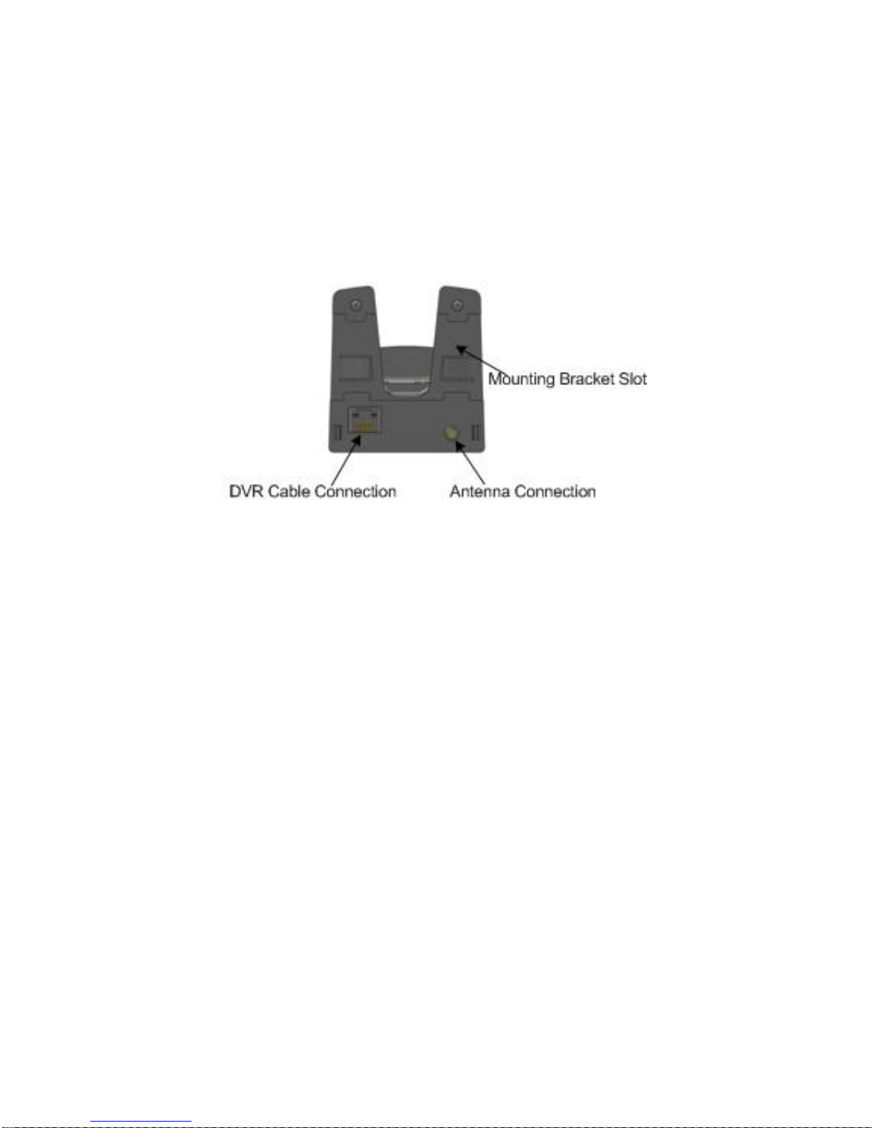
DVR Cable Connection
Connect the supplied digital video recording (DVR) system interface cable
to this point. This cable supplies power from the DVR to the Base device
when the DVR power is turned on. This cable also transfers the audio
signal from the microphone system to the DVR for inclusion in the DVR
video recording.
Figure 1: Base Back
WGD00091 - 7 -
Revision A
Base Unit Features
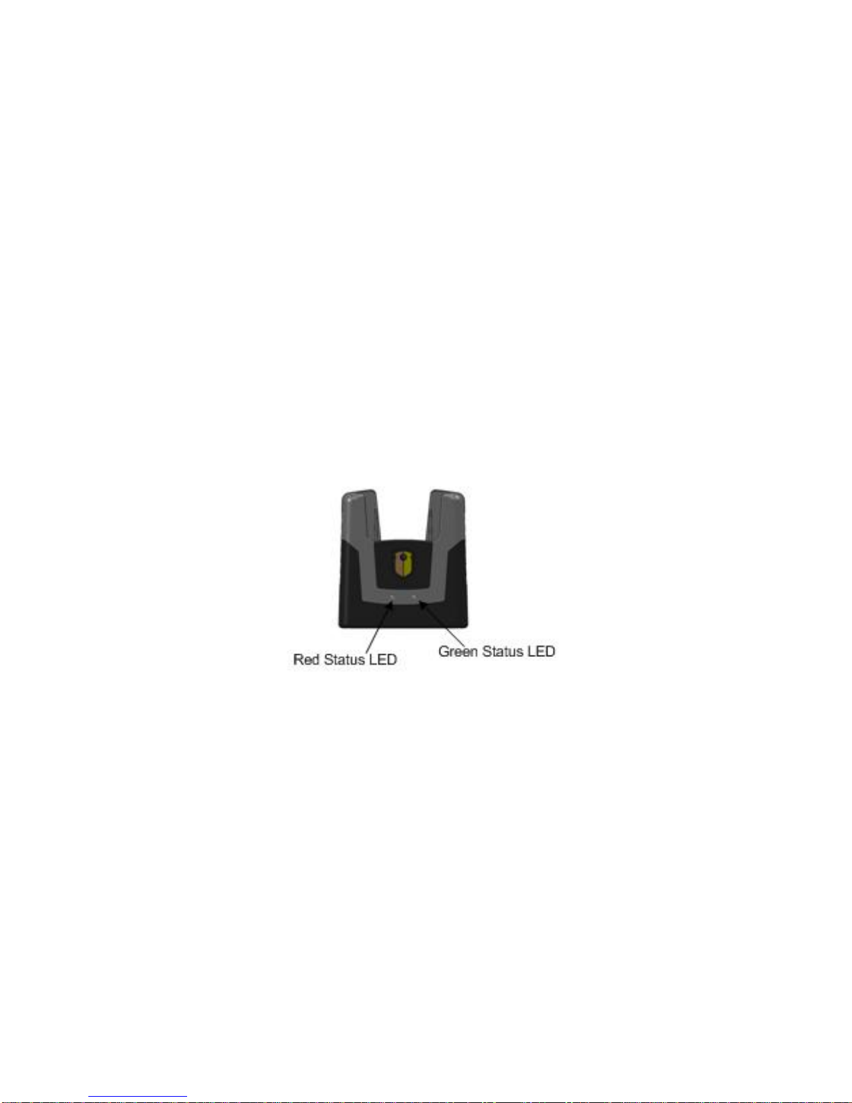
Red and Green Status LEDs
Please reference Figure 2.
The green LED on the Base will light when communicating with the
Transmitter device. The LED will light solid green when a voice recording
is enabled. During a voice recording, this LED will flash when the
Transmitter is muted. When a recording is not active, this LED will flash
when the Base is attempting to associate (bind) with a Transmitter device.
The red LED on the Base will light when the transmitter is inserted into
the base. The LED will light red when the battery is charging. The green
LED will light when the battery is fully charged.
Figure 2: Base Front
Binding a Base with a Transmitter
To function correctly, a specific Transmitter device must be bound or
associated with a specific Base. This is the process that allows the Base
and Transmitter to communicate wirelessly without interfering with other
Base/Transmitter pairs.
To bind a Transmitter to a Base, ensure the Base device is properly
installed in a vehicle as describe above. Power-on the DVR to apply
power to the Base. Insert the Transmitter device into the Base cradle fully
- 8 - WGD00091
Revision A

until the contacts on the bottom of the Transmitter (Figure 5) connect with
the contacts on the Base (Figure 3).
The Base and Transmitter LEDs will flash briefly. After a few seconds,
the binding process is complete. The Base and Transmitter are now ready
for normal use.
Figure 3: Base Top View
Figure 4: Base Bottom
WGD00091 - 9 -
Revision A

SYSTEM CONTROLS AND FEATURES
Transmitter Unit Features
Transmitter Power On/Off
Refer to Figure 5. Use this switch to turn the Transmitter device power on
and off. This switch must be in the ON position for all Transmitter-
recording functions to operate properly.
Figure 5: Transmitter Bottom
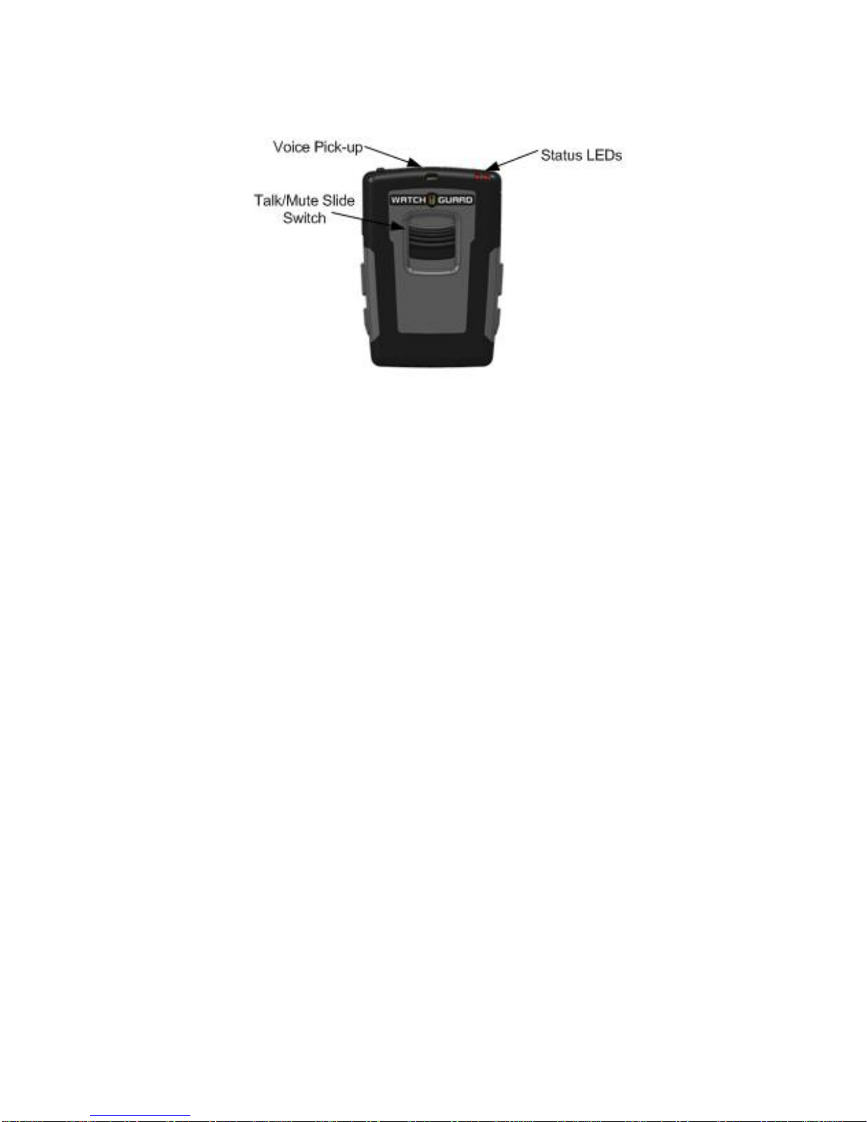
Talk/Mute Slide Switch
Refer to Figure 6. This control is used to enable microphone voice
recording and to mute the audio during a recording. When the Transmitter
power is turned on and the transmitter is bound with the Base, slide this
control down to begin voice recording. Once activated, the green
Transmitter LED will light and remain solid. Pressing the button again
will stop the recording function if the DVR is configured for this behavior.
The green Transmitter LED will turn off.
Behavior of the slide switch function can be overridden by the video
system (DVR). Settings on the DVR system can, for example, force the
recording function to remain on even though the Transmitter slide switch
is pressed. See the DVR system user manual for complete details.
Mute
With Transmitter voice recording enabled, the slide switch can be pressed
and held to suppress detection of the voice by both the internal and
externally connected (lapel) microphones. Once this switch is help down,
the green Transmitter LED will flash. The Transmitter will continue to
- 10 - WGD00091
Revision A
keep the recording enabled but there will be no voice audio present in the
recording. Release the slide switch to re-enable the voice audio; the
Transmitter LED will go back to a solid green LED.
Figure 6: Transmitter Front
Status Indicators
Refer to Figures 7 and 8.
Battery Level Indicator
This icon shows the level of remaining charge available for the
Transmitter battery.
Signal Strength Indicator
This icon shows the quality of the wireless signal connection to the Base.
Audio Status Indicator
This icon lights when the Talk/Mute slide switch is pressed to start an
audio recording.
Mute Status
This icon lights when the Talk/Mute slide switch is pressed during a
recording to mute the audio.
Backlight Status
This icon shows when the LCD backlight is active or not.
WGD00091 - 11 -
Revision A
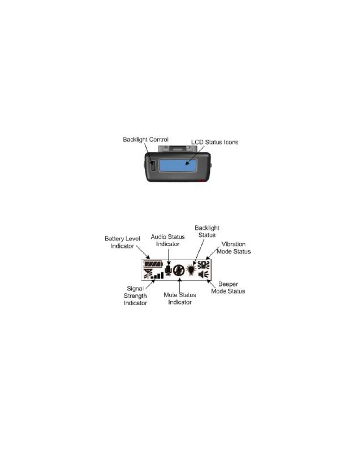
Vibration Mode Status
This icon shows when the vibration notification mode is selected.
Beeper Mode Status
This icon shows when the beep notification mode is selected.
LCD Backlight Control Button
Press this button to turn on the LCD backlight. This will allow the LCD
status icons to be more easily viewed in low light conditions.
Figure 7: Transmitter Top
Figure 8: LCD Status Icons
Mode Button
Refer to Figure 9. The mode button is used to select the notification
mode. The default notification mode is a beep. Pressing this button will
change the mode to vibrate. Pressing it again will change the mode to a
beep and vibrate combination. Pressing it again will disable the
notification mode. Pressing it again will select the default beep mode. The
notification mode selection rotates in a sequence of Beep > Vibrate >
Beep + Vibrate > Silent for each button press.
- 12 - WGD00091
Revision A

Covert Mode
Covert mode disables all light and sound coming from the Transmitter
device. To enter covert mode, hold the mode button down for 3 seconds.
Once in covert mode, the LCD backlight, green LED and red LED will be
disabled. The LCD status icon will still show the current status of the
system. The backlight status LCD icon will indicate the system is in
covert mode.
To exit covert mode and return to normal operation, depress the mode
button for 3 seconds or, press the mode button twice.
Figure 9: Transmitter Left Side
WGD00091 - 13 -
Revision A
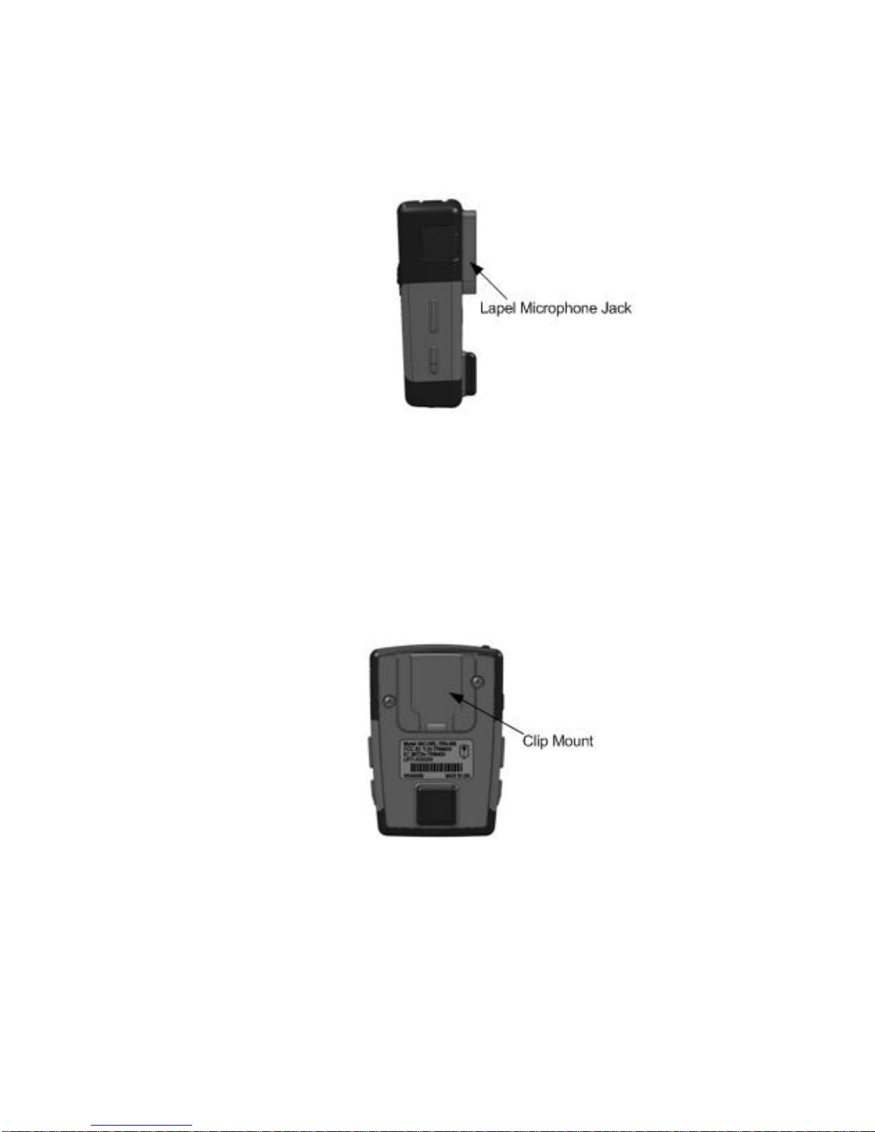
Lapel Microphone Jack
Refer to Figure 10. Connect the accessory lapel microphone to this jack.
Figure 10: Transmitter Right Side
Transmitter Belt Clip
Refer to figure 11. To attach one of the accessory belt clips to the
Transmitter, position the clip in the clip mount slot on the back of the
Transmitter and press down until it locks into place.
Figure 11: Transmitter Back
- 14 - WGD00091
Revision A

WGD00091 - 15 -
Revision A
SET UP AND OPERATION
Binding the Transmitter and Base
1. Ensure the DVR is installed properly and the RJ-45 signal cable is
connected to the microphone base.
2. Turn on the DVR power.
3. Turn the microphone Transmitter power switch to ON and place the
Transmitter in the recharge cradle of the Base. The Transmitter goes in
the base with the WatchGuard logo facing out.
4. The Base’s green LED and the Transmitter LED will both light and flash
during the binding operation. Once the binding operation is successful,
the LED on the Base and the LED on the Transmitter will go dark. (If the
green LEDs continue to flash, biding is not successful. See the
troubleshooting section of this manual.)
5. The Transmitter and Base are now bound and will continue to be bound
until another Transmitter is linked to that Base.
Normal Operation
1. With the Transmitter bound to the Base, remove it from the cradle, plug
in the lapel microphone (if used) and place the Transmitter on your belt
holster.
2. To start the recording, press the Talk/Mute button. The Transmitter’s
LED will light a constant green. Voice recording is now enabled and all
audio detected by the microphone will be saved with the DVR system
video.
3. To end recording, press the Talk/Mute button, The green Transmitter and
Base LEDs will turn off.
4. At the end of your shift turn the transmitter OFF by sliding the
Transmitter power switch to the OFF position. Replace the Transmitter in
the Base charging cradle.
Out of Range
If you use the Transmitter too far away from the Base during recording, the
transmitter will alert you with the selected notification mode and the Transmitter’s
red LED will light.
Move closer to the Base and the link will be re-established. The LED will
go out when link is back to normal operation.
If you went out of range in Standby mode (voice recording off), re-enter
normal range and operation will return to normal.
If you will be out of range for a long period of time, turn the Transmitter
off.

- 16 - WGD00091
Revision A
Low Battery Warning
If the Transmitter beeps and the red LED flashes, return the transmitter to its
base charging cradle to fully charge the transmitter.
The Base’s LED indicator will light constant green when the unit is fully charged.

WGD00091 - 17 -
Revision A
GUIDELINES AND RECOMMENDATIONS FOR
BEST PERFORMANCE
Compatibility
The Transmitter and Base must be bound to work together by placing the
Transmitter into the charging cradle of the Base while the Base power is on. The
Base and the Transmitter’s LEDs will flash until binding occurs. Any Transmitter
can be bound with any Base.
Using Multiple Wireless Systems
The system has multiple “channels” that are really different frequency hopping
schemes. Each bound Base and Transmitter will automatically find a clear
channel so up to 26 systems can work together in one location depending on
other interference problems.
Potential Sources of Interference
There are many potential sources of interference for your wireless microphone
system. The microphone operates in the 900MHz frequency band and other
devices in that band may interfere. The spread spectrum technique used in the
microphone is very robust and should operate even in the presence of other
900MHz devices.

TECHNICAL SPECIFICATIONS
Operating Voltage Transmitter: 3.7VDC Base: 12VDC
Frequency 900MHz (902.25 ~ 928.00 MHz) – 52 channels, digital
spread spectrum
Operating Range 1 mile in open line of sight
* Note : Operating Range can be different according to the
environment
LED Indicators Transmitter: low battery warning, Out of Range, Talk On,
Mute
Base: Charging indicator, Talk On
Jacks Base: 8 pin RJ-45 for power, audio out, and trigger out
Transmitter: Lapel microphone jack
Battery Capacity: Lithium-ion 3.7V DC/1200mA
Charging time: 3 hours
Talk Time: Max. 8 Hours
Stand-by time: 25 days
TROUBLESHOOTING
Problem Check Points
No reception - Check the battery status
- Check the connection and cables
- Check the communication range
Poor reception,
static, noise - Change the location of Base or antenna
- Check the communication range
Unit does not
respond or
synchronize
- Check the battery status
- Check the power switch on the Transmitter
- Check the connection and cables
- 18 - WGD00091
Revision A

WGD00091 - 19 -
Revision A
WARRANTY
WatchGuard Video, in recognition of its responsibility to provide quality systems,
components, and workmanship, warrants each system, part, and component it
manufactures first sold to an end user to be free from defects in material and
workmanship for a period of ONE-YEAR from the date of purchase. A defective
component that is repaired or replaced under this limited warranty will be covered for the
remainder of the original warranty period. Where defects in material or workmanship
may occur, the following warranty terms and conditions apply:
WARRANTOR – This warranty is granted by WatchGuard Video, 415 Century
Parkway, Allen, TX 75013, Telephone: 972-423-9777, Facsimile: 972-423-9778.
PARTIES TO WHOM WARRANTY IS INTENDED – This warranty extends
to the original end user of the equipment only and is not transferable. Any exceptions
must be approved in writing from WatchGuard Video.
PARTS AND COMPONENTS COVERED – All parts and components and
repair labor of the warranted unit manufactured and/or installed by WatchGuard Video
are covered by this warranty, except those parts and components excluded below.
PARTS AND COMPONENTS NOT COVERED – The Limited Warranty
excludes normal wear-and-tear items such as frayed or broken cords, broken connectors,
scratched or broken displays or consumable items such as batteries. WatchGuard reserves
the right to charge for damages resulting from abuse, improper installation, or
extraordinary environmental damage (including damages caused by spilled liquids) to the
unit during the warranty period at rates normally charged for repairing such units not
covered under the Limited Warranty. In cases where potential charges would be incurred
due to said damages, the agency submitting the system for repairs will be notified.
Altered, damaged, or removed serial numbers results in voiding this Limited Warranty. If
while under the warranty period, it is determined that the WatchGuard Video system was
internally changed, modified, or repair attempted, the system warranty will become null
and void.
LIMITED LIABILITY – WatchGuard Video’s liability is limited to the repair or
replacement of components found to be defective by WatchGuard Video. WatchGuard
Video will not be liable for any direct, indirect, consequential, or incidental damages
arising out of the use of or inability to use the system even if the unit proved to be
defective. WatchGuard Video will not be responsible for any removal or re-installation
cost of the unit or for damages caused by improper installation.
REMEDY – If, within the duration of this warranty, a unit or component covered by
this warranty is returned to WatchGuard Video and proves to be defective in material or
workmanship, WatchGuard Video shall (at its option) repair or replace any defective
components or offer a full refund of the purchase price . Replacement of a defective

- 20 - WGD00091
Revision A
component(s) pursuant to this warranty shall be warranted for the remainder of the
warranty period applicable to the system warranty period.
SHIPPING – During the first ninety (90) days of the initial warranty period,
WatchGuard Video will provide a prepaid shipping label to return any defective unit for
end users in the continental United States provided serial numbers are submitted with
request. In such event, contact WatchGuard’s Customer Service Department to request a
return material authorization (RMA) number. Failure to obtain and use a WatchGuard
Video prepaid shipping label in the first ninety days (90) on the return shipment will
result in the end user being responsible for shipping costs to WatchGuard Video. After
the first ninety (90) days, the end user will be responsible for any shipping charges to
WatchGuard Video. WatchGuard Video will return ship the product to a customer within
the continental United States by prepaid ground shipping only. Any expedited shipping
costs are the responsibility of the end user.
Customers that are outside the continental United States will be responsible for all
transportation costs both to and from WatchGuard Video’s factory for warranty service,
including without limitation to any export or import fees, duties, tariffs, or any other
related fees that may be incurred during transportation.
You may also obtain warranty service by contacting your local WatchGuard Authorized
Service Center (ASC) for shipping instructions. A list of local ASCs may be obtained by
contacting WatchGuard’s Customer Service Department. Customers will be responsible
for all transportation costs to and from the local ASC for warranty service.
EXTENDED WARRANTY – Extended Warranties may be purchased directly from
WatchGuard Video. Any and all extended warranties must be purchased prior to the
expiration of any previous warranty. Failure to purchase an extended warranty prior to
the expiration of the warranty period will require the covered unit to be physically
inspected at the facility of the manufacturer and any repairs necessary to bring the unit
back to full working order must be performed prior to the issuance of any new warranty.
The customer will be responsible for the cost of the inspection (equal to 1 hour of labor)
plus the standard costs associated with any required repairs. Should you have any further
questions regarding the WatchGuard Video limited warranty, please direct them to:
WatchGuard Video
Attn: Customer Service Department
415 Century Parkway
Allen, Texas 75013
(800) 605-6734 Toll Free Main Phone
(866) 384-8567 Toll Free Queued Customer Service
(972) 423-9777 Main
(972) 423-9778 Fax
www.watchguardvideo.com
support@watchguardvideo.com
Table of contents
Other Watchguard Microphone manuals


