Water Furnace IntelliZone User manual

IntelliZone Installation Manual
Installation Information
Damper Installation
Thermostat Installation
Electrical
Startup Procedures
Wiring Schematic
Comfort Zoning System
Four Zone Capability
™
IM1958 03/09

™
Staging
Effective July 2006, the company introduced a software upgrade to the IntelliZone that allows 4 different comfort
staging options. The available conguration options are Normal, Quicker, Faster and Faster w/Timer. (The Slower stag-
ing option has been removed from the new version of the IntelliZone.)
Normal –
This “as-shipped” mode will upstage the blower and compressor normally and remains unchanged from the
current IntelliZone.
Quicker –
This mode will upstage the blower, compressor and auxiliary electric heat more expediently than Normal
mode for increased comfort.
Faster –
This mode will upstage the blower and auxiliary electric heat slightly faster than Quicker mode. Cooling
operation is same as Quicker mode.
Faster w/ Timer –
This mode allows for a timed element in compressor and electric heat upstaging for situations in
which normal staging is inadequate. Cooling operation is same as Quicker. This staging position should be reserved
for the most demanding and aggressive situations.
Conguring the IntelliZone for Quicker, Faster or Faster w/Timer will give added comfort but will also result in in-
creased system operating costs and should be used only when necessary.
A kit is available for purchase that will include a microchip and instructions for retrotting older IntelliZone systems
with the enhanced operation logic. The kit’s part number is IRC.
Downstaging
Dual stage (E-Series and Envision) units have the ability via DIP switch SW3-2 to satisfy a call normally (Y2 down-
stage to Y1 to nish) or nish on second stage (Y2 runs to nish the call). The units are shipped from the factory with
DIP switch SW3-2 OFF which will enable the unit to nish a call with normal downstaging. When using the Intellizone it
is necessary to ensure that SW3-2 is in the OFF position so that downstaging will work properly.
Minimum Airow Setting
Envision dual capacity units have 70% low capacity, compared to E Series dual capacity and older Premier two
speed units with 50% low capacity. This will change the minimum zone CFM from 25% of nominal (400 CFM/ton) to
40% of nominal. Therefore, when using the IntelliZone with an Envision dual capacity or Synergy3D unit, the zone
branch ducts must be sized to handle MORE airow.
IntelliZone – What’s New?

1
INTELLIZONE INSTALLATION MANUAL
Table of Contents
General Installation Information 2-3
Damper Installation 4-6
Electrical Wiring 7-9
Thermostat Installation 10-11
Blower Motor Wiring Harness Installation 12
DIP Switch Setup 13-15
Blower Data 16-18
System Startup and Checkout 19-20
Wiring Schematic 21

2
INTELLIZONE INSTALLATION MANUAL
General Installation Information
Safety Considerations
Installing and servicing heating and air conditioning equipment can be hazardous due to system electrical components.
Only trained and qualied service personnel should install, repair or service heating and air conditioning equipment. When
working on equipment, observe precautions in the literature, tags and labels attached to the unit, and other safety precau-
tions that may apply.
Follow all safety codes. Wear safety glasses and work gloves.
Delivery Information
When the equipment is received, all items should be carefully checked against the bill of lading to be sure all crates and
cartons have been received. Examine the contents for shipping damage, removing them from the cartons if necessary. If
any damage is noted, the carrier should make the proper notation on the delivery receipt, acknowledging the damage.
General rules to follow when installing a zone system:
Up to four zones with dual capacity units (two with single-speed units).•
All dampers should be located as close to the main trunk as possible to limit the amount of pressurized trunk line and •
thus limit air leakage.
No less than three branch runs in a zone to prevent a single branch obstruction (curtains or clothes etc.) from affect-•
ing unit airow.
Insulate and seal around rectangular dampers to prevent leakage.•
All dampers must be wired with 18-gauge wire.•
Note: Crimp connections should never be used on solid conductor wire.
Insure that the transformer can handle the power requirements of the system.•
No more than three dampers per zone.•
Ductboard-mounted dampers should be supported within six inches of the damper due to the weight and stress on•
the ductboard.
Unit DIP switch #3-3 should be in the NO RPM mode.•
Unit DIP switch #3-2 should be in the OFF position when used with a zone control system.•
Unit DIP switch #2-8 should be in the ON position (continuous ‘L’ signal) when used with a zone control system.•
Installation and Design Steps
Decide which areas of a home or ofce will comprise each of the individual zones. A maximum of four individual zones
1.
(two with single-speed equipment) can be chosen.
Calculate loads using software or other recognized methodology.
2.
Use software to determine the equipment size and performance based on the total heating and cooling demands of the
3.
building, not the sum of the individual zone demands.
Find the peak heating and cooling demands and the peak CFM required for each of the zones.
4.
Note: Dual Capacity Envision has a 70% low capacity output, therefore minimum CFM required per zone is 40% of
nominal CFM, signicantly higher than the E Series with a 50% low capacity output.
Determine zone design air ow and zone size settings using IntelliZone Calculator software.
5.
Lay out and size the supply air ductwork and IntelliZone dampers. Care should be taken to avoid under sizing either the
6.
supply air systems, return air systems, or diffusers.
Decide where to locate the thermostats.
7.
Install the unit and the IntelliZone Comfort Zoning system.
8.
WARNING:
Before performing service or maintenance operations on the system, turn off main power switches to
the indoor unit. Turn off accessory heater power switch if applicable. Electrical shock could cause serious personal
injury.
CAUTION: When installing the IntelliZone in a structure with fossil fuel (oil, gas, propane) appliances, it is impor-
tant that both supply and return dampers are used in each zone to avoid potential back-drafting of fossil-fueled
appliances.
3
INTELLIZONE INSTALLATION MANUAL
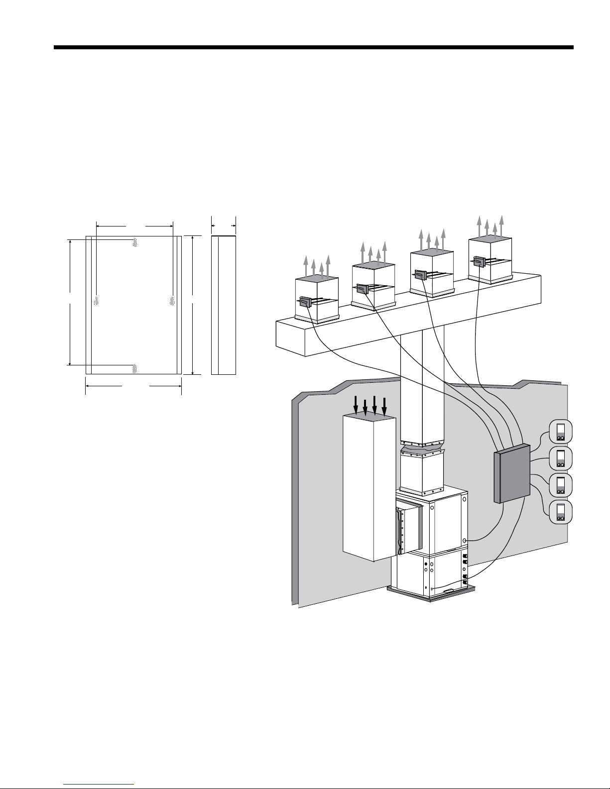
IntelliZone Control Panel
Locate the IntelliZone panel in an indoor area that has enough space for service personnel to perform maintenance or
repair. Provide sufcient room to make electrical connection(s). The IntelliZone is not approved for outdoor installation and,
therefore, must be installed inside the structure being conditioned. Do not locate the control panel in areas where ambient
conditions are not maintained within 45°F to 95°F and are greater than 75% relative humidity. The IntelliZone control panel
should be mounted on or as close to the unit as possible by using the sheet metal screws provided. See Figure 1 for mount-
ing hole locations.
Four Zone System Representational Layout
72
72
72
72
Premier2
9.00” 1.75”
14.50”
13.00”
11.125”
Figure 1: IntelliZone Control Panel Mounting
Notes: Use longer screws (not provided) to
penetrate through drywall into stud.
General Installation Information (cont.)

4
INTELLIZONE INSTALLATION MANUAL
Installing Rectangular Dampers in Metal Ductwork
Cut out dimensions A and B as shown in Figure 2 below by1.
using sheet metal snips.
Note: Dimensions A and B are listed in the table to the right.
Use foam insulation tape on the top and bottom of the zone damp-2.
er to prevent excessive air leakage. Also check the cross emboss
for excessive air leakage (see Figure 2).
Slide the zone damper into the ductwork making sure no obstructions will interfere with damper blade operation.3.
Use the screws provided to mount the damper ange to the ductwork. Four to six mounting holes are provided as 4.
shown in Figure 3 below.
Use drive cleats or regular duct mounting brackets to attach ductwork to joist within six inches on both sides5.
of the damper (see Figure 3).
Check damper blade operation for obstructions by holding the manual release button and rotating the damper shaft6.
CW (Open) and CCW (Closed) 3 Wire only as shown in Figure 4 below.
Damper Installation
Manual release
CCW
Closed
CW
Open
Rotate by hand
Figure 4: Checking Damper Blade for Obstructions
Damper Model H W A B
10"24" 10" 3.75"
8 " 12" 8" 3.75"
ZDR1024
ZDR0812
Dimensional Examples
Cross emboss for
duct stiffness may
cause excessive
air bypass
Foam Seal
Foam Tape
(top and bottom)
A
B
3.75”
Figure 2: Foam Taping Zone Damper Figure 3: Mounting Damper
Mounting Screws
(4 places)
Attach duct/damper
to joist within 6" on
both sides
5
INTELLIZONE INSTALLATION MANUAL
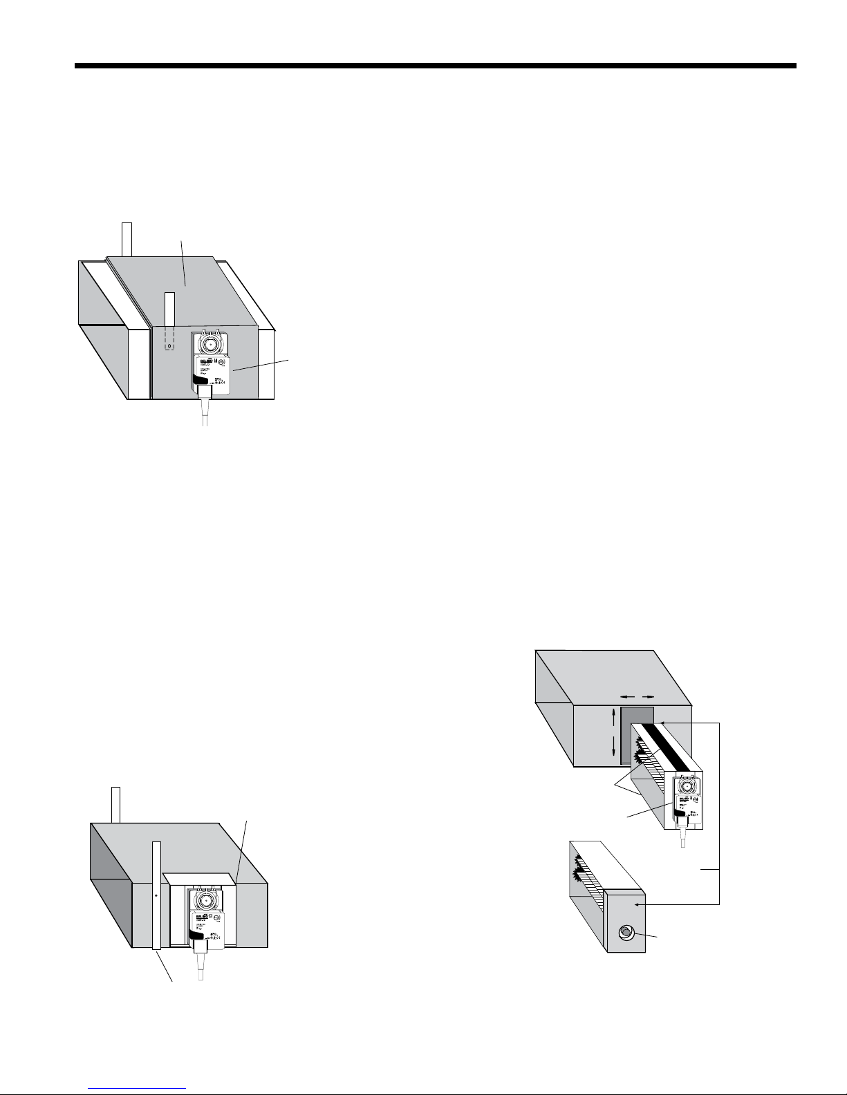
Insulating Rectangular Dampers in Metal Ductwork
Insulate ductwork as shown in Figure 5 below. All metal must be covered. Care must be taken not to obstruct the shaft
from rotating when insulating. Do not insulate the zone damper actuator.
Installing Rectangular Dampers in Ductboard
Cut out dimensions A and B by using a ductboard knife. Note: Dimensions A and B are listed in the Table on page 6.
1.
A ductboard spacer should be installed on the end of the damper frame as shown in Figure 7 to prevent excessive air
2.
bypass. For example: A one-inch-thick, 8’’x 20’’ ductboard and a 8’’ x 20’’ zone damper would have a one-inch gap at
the end of the frame once it is installed without a ductboard spacer. Use the piece cut out for installation.
Foam insulation tape should be used on the top and bottom of the zone damper to prevent excessive air leakage as
3.
shown in Figure 7.
Slide the zone damper into the ductboard making sure no obstructions will interfere with damper blade operation.
4.
Tape the damper face ange to the ductboard using foil tape mak-
5.
ing sure the damper is secure and air tight as shown in Figure 8
below.
Support the full length of the ductboard underside within six inches
6.
and on both sides of the damper as shown in Figure 8.
Check the damper blade operation for obstructions by holding the
7.
manual release button and rotating the damper shaft CCW and CW
(see Figure 4 on page 6).
Damper Installation (cont.)
Do not insulate zone damper actuator
Duct wrap insulation
A
B
Duct board
Keep spacer clear
of end bushing
Foam tape
(top and bottom)
Insulate between
actuator and damper
spacer
Figure 5: Insulating Rectangular Metal Ductwork
Figure 7: Taping Zone Damper with Foam Tape
Foil tape damper face
to ductboard
Support the full length of ductboard
underside within 6” of damper
Figure 8: Taping Damper Flange to Ductboard

6
INTELLIZONE INSTALLATION MANUAL
Insulating Rectangular Ductboard/Metal Sleeve
Care must be taken not to obstruct the shaft from rotating when insulating. Do not insulate the zone damper actuator.
Installing Circular Dampers in Round Metal Duct
Crimp the end of the duct that is the supply air to damper. Insert into circular damper no more than 1.5 inches.
1.
Fasten the duct to the damper with three screws. Screws installed more than one inch from either end may obstruct
2.
damper blade rotation.
Seal completely around the duct with metal duct tape or mastic to prevent air leakage as shown in Figure 10 below.
3.
Check the damper blade operation for obstructions by holding the manual release button and rotating damper shaft
4.
CCW and CW (3 wire only). See Figure 4 on page 6.
Support the duct to joist within six inches of the damper as shown in Figure 9.
5.
Insulating Circular Dampers in Round Metal Duct
Insulate ductwork as shown in Figure 10. All metal must be covered to prevent condensation. Care must be taken not to
obstruct the shaft from rotating when insulating. Do not insulate the zone damper actuator.
Installing Circular Dampers in Flexible Duct
Slide exible duct two to three inches over the damper pipe past the damper rib as shown in Figure 11 below.
1.
Fasten duct to damper with a nylon duct strap, screwing the strap to the pipe to prevent the duct from slipping off.
2.
Screws installed more than one inch from either end may obstruct damper rotation.
Seal completely around the duct with metal duct tape or mastic to prevent any air leakage.
3.
Check the damper blade operation for obstructions by holding the manual release button and rotating damper shaft
4.
CW (Open) and CCW (Closed) - 3 wire only. See Figure 4 on page 6.
Support the damper to joist within six inches on both sides of the damper as shown in Figure 12.
5.
Insulating Damper Actuators
Insulate the damper as shown in Figure 12 below. All metal must be covered to prevent condensation. When insulating,
care must be taken not to obstruct the shaft from rotating. Do not insulate the zone damper actuator.
Damper Installation (cont.)
Flexible duct
Clamp with duct strap. Install screw no farther
than 1” from either end of damper.
Slide duct 2-3’’ past
damper end rib
Air Flow
Support with wide
steel strap
1-1/2’’ or 2’’ if in unconditioned space
Do not insulate
damper actuator
Figure 12: Supporting and Insulating Circular DamperFigure 11: Attaching Flexible Duct to Damper
Three screws sealed
with duct tape or mastic
Manual release button
Air Flow
Figure 9: Taping Round Duct to Circular Damper
Do not insulate
damper actuator
1-1/2" or 2" if in unconditioned space
Support with
wide steel strap
Figure 10: Supporting and Insulating Circular Damper

7
INTELLIZONE INSTALLATION MANUAL
Wiring Damper Actuators
All wiring must comply with local and state codes. Disconnect the power supply before beginning to wire to prevent elec-
trical shock or equipment damage. All wiring should be run back to the control panel. Keep wires a minimum of 12 inches
from any high voltage lines. Follow the damper wiring schematic as shown in Figure 13. Verify that damper rotation direction
is correct. The 3-wire damper rotation direction is reversible with switch on front cover.
Damper Actuator Wiring Notes:
Minimum of 18-gauge thermostat wire is recommended.
1.
Use wire nuts to connect the thermostat wire to the actuator wire (solid wire to stranded wire) as shown in Figure 14
2.
below.
The actuator wiring should be secured using a wire tie to prevent the wires from being separated (see Figure 14).
3.
3-Wire Damper
Blk
Red
Grn
COM
CCW
CW
Zone 4
IntelliZone PCB
Com
Open
Close
G
2-Wire Damper
Minimum
18-gauge wire
Zone 4
IntelliZone PCB
Com
Open
Close
G
COM Gray
CCW Yellow
Minimum
18-gauge wire
Note:
1. Each zone must have
dampers that match by
manufacturer and type.
2. Each IntelliZone
System must have
dampers that match,
either 2-wire or 3-wire.
(Indicated rotation direction
is valid for switch position ‘0’ )
Figure 13: Damper Actuator Wiring
Electrical Wiring
Wire Nuts
Figure 14: Actuator Wiring

8
INTELLIZONE INSTALLATION MANUAL
Transformer Sizing
Providing adequate transformer power (VA) to supply the system is an important requirement. Each IntelliZone 3-wire
damper requires 3.0 VA at nominal voltage. Each IntelliZone 2-wire damper requires 7.0 VA at nominal voltage. The stan-
dard transformer available is a 75VA with circuit breaker (Part # ZTK240).
Mount the transformer onto the side of the unit’s control box by inserting and tightening screws (provided) into the pre-
punched holes. Thread all transformer wires through the hole with bushing and follow the wiring schematic for connecting
the transformer primary leads as shown in Figure 15 below.
For 208 volt operation, the red and blue transformer wires must be switched. Follow the wiring schematic in Figure 16 on
page 11 for the secondary side of the transformer. Use wire nuts only for connections to thermostat wire.
Electrical Wiring (cont.)
WARNING:
All wiring must comply with local and state codes. Disconnect the power supply before beginning to
wire to prevent electrical shock or equipment damage.
Figure 15: Mounting Transformer to Control Box (E Series shown)
Transformer 'VA' Calculation (3-wire actuator)
Zone 1 dampers Power to 2 IntelliZone Damper 6.0VA
Zone 2 dampers Power to 1 IntelliZone Damper 3.0VA
Zone 3 dampers Power to 2 IntelliZone Damper 6.0VA
Zone 4 dampers Power to 3 IntelliZone Damper 9.0 VA
Total VA Draw 24 VA
IntelliZone
transformer
(Mount with
wires pointing up)
Wrap end of unused
transformerwirewith
electrical tape and
secure inside the
control box away
from other electrical
terminals
SW 3-2 must be set to OFF
(Zone) on logic board when
used with zone control system.
Connect IntelliZone
transformer primary leads
to “A” and“C” on the
terminal block for proper
operation.

9
INTELLIZONE INSTALLATION MANUAL
Wiring IntelliZone to the Unit
Follow the wiring schematic in Figure 17 for unit
control connections. Strip the wires back 1/4 inch
(longer strip lengths may cause shorts) and insert the
thermostat wires into the unit’s connector as shown in
Figure 17. Tighten the screws to ensure tight connec-
tions. Use a minimum of 18-gauge thermostat wire for
connections. SW 3-2 must be set to OFF on the logic
board when used with a zone control system. SW 2-8
must be set to ON (continuous ‘L’ signal) when used
with a zone control system.
Electrical Wiring (cont.)
Figure 16: 24 Volt Transformer Wiring (Envision shown)
Note: The IntelliZone control board must be grounded to the
unit to operate properly.
WARNING:
All wiring must comply with local
and state codes. Disconnect the power supply
before beginning to wire to prevent electrical
shock or equipment damage.
13
Y1
Y2
W
O
G
Unit
Control Board
IntelliZone Control
18-Gauge thermostat wire
G
G
Y
G
R
G
LO
O
W
Y2
G
Y1
C
R
LO
O
W
Y2
G
Y1
C
R
= Green LED
= Red LED
= Yellow LED
G
Y
R
Figure 17: IntelliZone to Premier Control Wiring
L1
L2
2
1
3
BLUE
BLACK
IntelliZone Control
18 gauge
thermostat wire
to IntelliZone
Control
GND
C
R
BLK/WHT
YELLOW
C

10
INTELLIZONE INSTALLATION MANUAL
Locating the Thermostats
The thermostats must be located in the room or zone that each controls. Locate a thermostat about ve feet above the
oor. Do not locate a thermostat where it may be exposed to direct sunlight, drafts or direct supply air. Do not place a ther-
mostat on an outside wall. Follow the same guidelines that apply with standard thermostat installation. If two or more rooms
are on a single zone, locate the thermostat in a hallway or area where it can sense the return air from all rooms.
Thermostat Installation
Figure 18: Four Zone Thermostat Location
Master
Bedroom
Bath
Bath
Bedroom
Bedroom
Kitchen
Living Room
Utility
Room
Dining
Zone 2 Bedrooms
Zone 1 Main Living
Zone 3 Master Suite
Zone 4 Basement
Not
Shown
Family
Room
IntelliZone Thermostat

11
INTELLIZONE INSTALLATION MANUAL
Thermostat Installation (cont.)
Mounting and Wiring the Thermostat
Position the thermostat subbase against the wall so that it is level
and the thermostat wires protrude through the middle of the subbase.
Mark the position of the subbase mounting holes and drill holes with
a 3/16-inch bit. Install supplied anchors and secure base to the wall.
Thermostat wire must be eight-conductor 18 AWG. Strip the wires
back 1/4 inch (longer strip lengths may cause shorts) and insert the
thermostat wires into the IntelliZone connector as shown in Figure
19 at right. Tighten the screws to ensure tight connections. The
thermostat has the same type connectors, requiring the same wiring.
Caulk the hole in the wall where the wires enter the thermostat.
Note: See the instructions enclosed in the thermostat for detailed
installation and operation information.
Thermostat Indicator Light Function
“Fault” or “Service Needed” will be displayed on the thermostat.
This text illuminates when a fault condition has occurred. A light on
the front lower panel of the unit will also illuminate to indicate what
condition caused the fault (except airow).
A slowly ashing “fault” light during unit operation indicates a
thermostat wiring problem. A rapidly ashing fault light indicates an
airow fault.
The thermostat may indicate a call for auxiliary heat when a high
heat demand is sensed in a zone. This does not necessarily indicate
that auxiliary heat is being energized in a zone system.
Note: ComforTalk or FaultFlash thermostat features are NOT
available with IntelliZone control boards.
Figure 19: Wiring the Thermostat to the IntelliZone
IntelliZone
Control
Zone One
C
Y1
Y2
R
C
Y1
Y2
Y3
G
O
LO
R
G
G
G
Y
G
P1 through P4
Thermostat
R
IntelliZone Zone Stat
Input
C
Y1
Y2
W
O
G
L1
R
C
Y1
Y2
Y3
O
G
L1
Zone Thermostat
18/8
Wire
1
2
3
Indicator Light Function
Operation Modes IntelliZone Outputs
Y1 Y2 W O G
Heating - 1st Stage ON OFF OFF OFF ON
Heating - 2nd Stage ON ON OFF OFF ON
Heating - 3rd Stage ON ON ON OFF ON
Heating - Emergency OFF OFF ON OFF ON
Cooling - 1st Stage ON OFF OFF ON ON
Cooling - 2nd Stage ON ON OFF ON ON
Constant Fan OFF OFF OFF OFF ON

12
INTELLIZONE INSTALLATION MANUAL
Blower Motor Wiring Harness Installation
Thread the ECM2 motor harness through the knockout in the air handler section of the unit. Use the 3/4-inch romex con-
nector provided for strain relief and to seal the blower compartment from ambient air. Place a section of cork tape from the
inside to the back of the Romex connector for additional sealing. Disconnect the existing blower harness.
Connect the new harness to the blower motor as shown in Figure 20, below. Strap the original harness to the new one
so that it is free of shorting/obstructing the blower wheel.
Thread the IntelliZone end of the harness through the zone cabinet and connect to the IntelliZone printed circuit board
(See Page 22).
WARNING:
Disconnect the power supply before beginning to wire to prevent electrical shock or equipment
damage.
Figure 20: Connecting New Wiring Harness to Blower Motor Wiring Harness
IntelliZone
ECM Motor
Harness
ECM2
Existing
harness from
unit control box
New harness
from IntelliZone
control
Disconnect
Connect
Notes: An ECM motor harness extension (ZBHE is available separately). Switch SW3-3 on the unit must be in the NO RPM
setting.

13
INTELLIZONE INSTALLATION MANUAL
IntelliZone Slide Switch Setup (SW1 Through SW4)
A three-position DIP switch package located on each zone section of the IntelliZone control allows the following eld
selectable zone options.
Zone setting DIP switches are located below each thermostat’s connections as shown in Figure 21 below.
Switch 1: Comfort/Economy Mode
This DIP switch allows the selection in each individual zone for either “Comfort” or “Economy” mode to provide maximum
savings in areas that allow it (such as workshops and basements), but still maintains comfort in the zones where accurate
temperature is most desired (such as bedrooms and baths).
Comfort mode - A single zone call (Y1) for conditioning will engage the compressor and minimize set point variation thus
providing ultimate comfort.
Economy mode - The economy mode will attempt to satisfy the zone demand without initiating a compressor call. A Y1 call
from a zone in the economy mode position will open the damper to the zone and call for the fan. It will use the return air from
the remaining zones to condition this zone. If the thermostat cannot be satised in this manner, the thermostat will deliver a
Y2 call starting the compressor in low capacity.
Switches 2 & 3: Zone Percentage
These DIP switches allow the eld selection of the zone percentage of the load as shown in Figure 22 below.
If both DIP 2 and 3 are off, the zone is inactive and dampers will be closed. •
If DIP 2 is on and 3 is off, the zone load percentage is 25%.•
If DIP 2 is off and 3 is on, the zone load percentage is 45%.•
If both DIP 2 and 3 are on, the zone load percentage is 70% (25% + 45%=70%).•
DIP Switch Setup
Zone settings DIP SW1 through SW4
IntelliZone
Control
C
Y1
Y2
Y3
G
O
LO
R
G
G
G
Y
G
Thermostat
1-
2-
3-
Priority - Economy/Comfort
Zone Size 25%
(Both on =70% neither on =0%)
Zone Size 45%
(Both on =70% neither on =0%)
Zone One
Figure 21: Setting Zone DIP Switches
Figure 22: Zone Percentage Selection by DIP Switch
Zone
Inactive 25% Zone 45% Zone 70% Zone
On On On On

14
INTELLIZONE INSTALLATION MANUAL
Selecting Zone Priority and Percentages
Selecting the zone percentage should be accomplished by using the Zone Calc Software. This percentage is an approxi-
mation of the maximum heating and cooling load of the zone. The IntelliZone allows 0, 25, 45 and 70% selections. Below
are some general rules to follow when selecting percentages:
Pick a larger percentage for major living areas such as family rooms, etc.•
Pick a smaller percentage for minor living areas such as dens or bedrooms.•
Pick a larger percentage if more branches are required than the load indicates due to large area per load (unnished •
basement).
The total should always add up to over 100%.•
Settings DIP Switch 6 (SW6)
An 8-position DIP switch package on the IntelliZone control allows the following eld selectable options:
1 - Service Test Mode
This DIP switch allows eld selection of “Normal” or “Test” operational modes (Test=OFF / Normal Speed=ON). The test
mode accelerates most timing functions, including the damper timing, 16 times to allow faster troubleshooting.
Note: Three-wire dampers will not have enough time to open in test position.
2 - Central Zone Mode
This DIP switch allows eld selection of “Central” or “Multi-zone” operational modes (Central Zone=OFF /
Multizone=ON). The central mode opens all dampers and operates the control as a central zone using the zone 1 (main)
thermostat inputs. This mode, which operates like a system without zone control, allows simplied operation during testing
or during emergencies. In multi-zone mode, the control allows each active zone to be controlled by its respective thermostat
inputs.
3 - No RPM/RPM Mode
This DIP switch congures the control to monitor the RPM output of the ECM2 blower motor (No RPM=OFF / RPM=ON).
When using a PSC blower motor, the control should be congured for “No RPM” sensing.
4 - Dehumidication Mode
This DIP switch allows eld selection of “Dehumid” or “Normal” operational modes. The “Dehumid” mode uses the logic
of reduced cooling fan speeds 1 and 2 for stage one compressor (Y1 on single-speed), and fan speed 3 and 4 for dual-ca-
pacity compressor (Y2 on single-speed). The “Normal” mode uses the logic of normal cooling fan speeds 2 and 3 for stage
one compressor (Y1 on single-speed), and fan speeds 4 and 5 for stage two compressor (Y2 on single-speed).
5 - Dual capacity/Single-Speed
This DIP switch congures the control for single-speed or dual capacity unit operation (Single-Speed=OFF / Dual Ca-
pacity =ON). Single-speed units are limited to two zones. Dual capacity units can operate up to four zones.
6 & 7 - Staging Options
Normal - This “as shipped” mode will upstage the blower and compressor normally.
Quicker - This mode will upstage the blower, compressor and auxiliary electric heat more expediently than “normal”
mode for increased comfort.
Faster - When heating, this mode will upstage the blower and auxiliary electric heat slightly faster than “quicker” mode.
Cooling operation same as “quicker” mode.
Faster with Timer - This mode allows for a timed element in compressor and electric heat upstaging in 45% and 70%
zones for situations in which normal staging is inadequate when heating. This staging position should be reserved for
the most demanding and aggressive situations. Cooling operation remains the same as “quicker” mode.
Example 1: The heat pump is already operating in rst stage. Second stage will be activated after a 15-minute continu-
ous Y3 zone call from a 45% or 70% zone until the zone call is reduced to a Y2. Airow will be increased to speed tap 3 or 4
during this period.
Example 2: The heat pump is already operating in second stage. Third stage will be activated after a 15-minute Y3
zone call from a 45% or 70% zone until the zone call is reduced to a Y2. Airow will be increased to speed tap 5 during this
period.
DIP Switch Setup (cont.)

15
INTELLIZONE INSTALLATION MANUAL
8 - Damper Timing
This DIP switch congures the control for IntelliZone “3-wire” or
other “2-wire” damper operation (Dampers-Spring [2-wire]=OFF /
Dampers-Intellizone [3 wire]=ON).
“3-wire” dampers require motorized opening and closing. In this
position, opening and closing damper relays energize for 90 sec-
onds allowing plenty of time for complete movement of the damper
to either the open or closed position.
“2-wire” dampers typically use a “stall” motor to close and a
spring to open. In this position, the opening and closing damper
relays are continually energized to power close the dampers for
maximum close off pressure.
SW8 (Jumper)
This is to match the Intellizone with the thermostats being used.
It should be on the center post and “AT” when a TA32E12 thermo-
stat is used. When using a 24 volt AC thermostat, it should be on
the center post and “24V”.
Emergency Heat DIP Switch 7 (SW7)
When conditions call for emergency heat, the unit automatically locks out and the electric heat is energized.
To engage emergency electric heat manually, remove the cover from the IntelliZone board. At the board, push and hold
the black emergency reset button, SW7, located on the middle of the board. Hold for three seconds then release. This will
place the unit into the emergency heat mode.
To turn off emergency heat, push and hold SW7 for three seconds, then release. This will disengage the emergency heat
mode and return the unit into the normal operating mode.
Note: This function cannot be performed from the thermostat.
Selecting Airow DIP Switches (SW5)
A 12-position DIP switch package on the IntelliZone control (shown in Figure 24 below) allows the airow levels to be set.
ECM2 fan motors have 12 different speeds. There are ve airow levels at which the ECM2 will operate depending on the
current load level of the structure. If the IntelliZone is controlling a dual capacity unit, there are two levels each for both low
and high capacity compressor operation. With a single-speed unit, there is one level for Y1 operation and two levels for Y2.
Only ve DIP switches can be in the ON position. The rst ON switch determines the continuous fan operation; the sec-
ond, the low speed; the third, the medium-low speed; the fourth, the medium-high speed and the fth, the high speed.
To change speeds, consult Figure 24 for specic airow and switch information.
DIP Switch Setup (cont.)
Figure 23: DIP Switch System Settings
System Settings
SW6
1 - Test/Normal Speed
2 - Central Zone/Multizone
3 - NO RPM/RPM
4 - Dehumid/Normal
5 - Single-Speed/Dual Capacity
6 - Staging Options (See Configuration Table)
7 - Staging Options (See Configuration Table)
8 - Dampers—Spring (2-wire)/IntelliZone (3-wire)
Off On
IntelliZone Control Unit
On
ECM2
Airflow Settings
ECM2 Motor
Gnd
Enab
RPM
PWM
NU
RGnd
Yel
Blk
Gray
Violet
Blue
1
2
3
4
5
6
Airflow
1
2
3
4
5
6
7
8
9
10
11
12
“G” only = 1 speed
First five
switches
in the “On”
position
determine
fan speed
SW5
P10
2 Speed
G
3 Speed
G
4 Speed
G
5 Speed
G
Gnd
Enab
RPM
PWM
RGnd
Figure 24: IntelliZone Control Board DIP Switches Fan Settings
Description SW6-6 SW6-7
Normal ON ON
Quicker OFF ON
Faster ON OFF
Faster w/Timer OFF OFF
Staging Conguration

16
INTELLIZONE INSTALLATION MANUAL
MAX AIRFLOW DIP SWITCH SETTINGS
MODEL ESP 1 2 3 4 5 6 7 8 9 10 11 12
600 700 800 900 1000 1100 1150 1225 1300
1 2 3 4 5
650 750 850 950 1050 1150 1250 1325 1375 1475
1 2 3 4 5
650 750 850 950 1050 1150 1250 1325 1375 1475 1550 1600
1 2 3 4 5
E040, P040 750 900 1000 1200 1400
w/1hp* 1 2 3 4 5
E047, P046 750 900 1000 1200 1400 1600 1700
w/1hp* 1 2 3 4 5
0.75 750 900 1000 1200 1400 1600 1700 1850 2000 2200 2300 2400
1 2 3 4 5
750 900 1000 1200 1400 1600 1700 1850 2000 2200 2300 2400
1 2 3 4 5
—— — — —
—
— — — — — — —
———
—
E066, P066
E035, P034
E040, P040
E047, P046
E058, P056
0.50
0.50
0.50
0.75
0.75
0.75
MAX AIRFLOW DIP SWITCH SETTINGS
MODEL ESP 1 2 3 4 5 6 7 8 9 10 11 12
600 700 800 900 1000 1100 1200 1300 1400 1500 1550 1600
123 4 5
600 700 800 900 1000 1100 1200 1300 1400 1500 1550 1600
1 2 3 4 5
E048 750 900 1000 1200 1400 1600 1700 1850 2000 2200 2300 2400
w/1hp* 1 2 3 4 5
0.75 750 900 1000 1200 1400 1600 1700 1850 2000 2200 2300 2400
1 2 3 4 5
750 900 1000 1200 1400 1600 1700 1850 2000 2200 2300 2400
1 2 3 4 5
0.50
0.50
0.75
0.75E072
E036
E048
E060
Premier and E Series Single-Speed Blower
Premier E Series Dual Capacity Blower
Notes: Factory settings are at recommended 1-2-3-4-5 DIP switch locations. Factory 1 setting is minimum allowed for cooling.
Settings 2-5 must be located within boldface CFM range. CFM is controlled within ± 5% up to the maximum ESP. Max ESP
includes allowance for wet coil and standard lter. Highest 5 DIP switch settings are assumed to be 1, 2, 3, 4, and 5. * With
optional one horsepower fan motor.
Notes: Factory settings are at recommended 1-2-3-4-5 DIP switch locations. CFM is controlled within ± 5% up to the maximum
ESP. Max ESP includes allowance for wet coil and standard lter. * With optional one horsepower fan motor.
Blower Data

17
INTELLIZONE INSTALLATION MANUAL
Blower Data (cont.)
Envision Single Speed ECM
Rev. 5/30/06Notes: Factory settings are at recommended 1-2-3-4-5 DIP switch locations. Factory 1 setting is minimum
allowed for cooling. Settings 2-5 MUST be located within boldface CFM range. CFM is controlled within ±5%
up to the maximum ESP. Max ESP includes allowance for wet coil and standard lter. Highest ve DIP switch
settings are assumed to be 1, 2, 3, 4 and 5. Factory L-M-H settings shown for comparison purposes only.
*With optional 1 horse power fan motor.
MODEL MAX
ESP
AIR FLOW DIP SWITCH SETTINGS
1234567891011 12
036 0.50 650 750 850 1000 1100 1200 1300 1400 1500
1 L 2 3 M 4 5 H
036
w/1hp* 0.75 800 1000 1100 1300 1500 1600 1800
12 L 3 M 4 H 5
042 0.50 650 800 900 1050 1150 1250 1350 1450 1550
1 L 2 M 3 4 5 H
042
w/1hp* 0.75 800 900 1000 1200 1400 1600 1700 1850 2000 2200 2300 2400
1 L 2 3 M 4 H 5
048 0.50 650 800 900 1050 1150 1250 1350 1450 1550
1 L 2 3 M 4 5 H
048
w/1hp* 0.75 800 900 1000 1200 1400 1600 1700 1850 2000 2200 2300 2400
1 L 2 M 3 H 4 5
060 0.75 800 950 1100 1300 1500 1750 1950 2100 2300
1 L 2 M 3 4 H 5
070 0.75 800 950 1100 1300 1500 1750 1950 2100 2300
1 L 2 M 3 4 H 5
MODEL MAX
ESP
AIR FLOW DIP SWITCH SETTINGS
1234567891011 12
038 0.50 650 750 850 1000 1100 1200 1300 1400 1500
1 L 2 3 4 M 5 H
038
w/1hp* 0.75 800 1000 1100 1300 1500 1600 1800
1 L 2 3 M 4 H 5
049 0.50 650 800 900 1050 1150 1250 1350 1450 1550
1 L 2 3 4 M 5 H
049
w/1hp* 0.75 800 900 1000 1200 1400 1600 1700 1850 2000 2200 2300 2400
1 L 2 3 4 M H 5
064 0.75 800 950 1100 1300 1500 1750 1950 2100 2300
1 L 2 3 M 4 H 5
072 0.75 800 950 1100 1300 1500 1750 1950 2100 2300
1 L 2 3 M 4 H 5
Envision Dual Capacity ECM
Rev. 5/30/06Notes: Factory settings are at recommended 1-2-3-4-5 DIP switch locations. Factory 1 setting is
minimum allowed for cooling. Settings 2-5 MUST be located within boldface CFM range. CFM is
controlled within ±5% up to the maximum ESP. Max ESP includes allowance for wet coil and standard
lter. Highest ve DIP switch settings are assumed to be 1, 2, 3, 4 and 5. Factory L-M-H settings shown
for comparison purposes only. *With optional 1 horse power fan motor.
Note: Dual Capacity Envision has a 70% low capacity output, therefore minimum CFM required per zone is
40% of nominal CFM, signicantly higher than the E Series with a 50% low capacity output.

18
INTELLIZONE INSTALLATION MANUAL
Envision Air Handler ECM with Envision Split Single Speed
Blower Data (cont.)
AIR HANDLER
MODEL
MAX
ESP
SPLIT
MODEL
AIR FLOW DIP SWITCH SETTINGS
1234567891011 12
NAH036 0.50 036 300 400 600 800 900 1000 1100 1200 1400
12345
NAH042 0.75 042 650 850 1100 1300 1500 1700 1850 1950 2100
12345
NAH048 0.75 048 650 850 1100 1300 1500 1700 1850 1950 2100
12345
NAH060 0.75 060 650 850 1100 1300 1500 1700 1850 1950 2100
12345
NAH060 0.75 070 650 850 1100 1300 1500 1700 1850 1950 2100
12345
10/27/08
NOTES: Factory settings are at recommended 1-2-3-4-5 DIP switch locations. Factory 1 setting is minimum allowed for cooling. Settings 2-5
MUST be located within boldface CFM range. CFM is controlled within +5% up to the maximum ESP. Max ESP includes allowance for wet coil
and standard lter. Highest ve DIP switch settings are assumed to be 1, 2, 3, 4, and 5.
Envision Air Handler ECM with Envision Split Dual Capacity
AIR HANDLER
MODEL
MAX
ESP
SPLIT
MODEL
AIR FLOW DIP SWITCH SETTINGS
1234567891011 12
NAH036 0.50 038 300 400 600 800 900 1000 1100 1200 1400
12 3 4 5
NAH048 0.75 049 650 850 1100 1300 1500 1700 1850 1950 2100
12345
NAH060 0.75 064 650 850 1100 1300 1500 1700 1850 1950 2100
12 3 4 5
NAH060 0.75 072 650 850 1100 1300 1500 1700 1850 1950 2100
12 3 4 5
10/27/08
NOTES: Factory settings are at recommended 1-2-3-4-5 DIP switch locations. Factory 1 setting is minimum allowed for cooling. Settings 2-5
MUST be located within boldface CFM range. CFM is controlled within +5% up to the maximum ESP. Max ESP includes allowance for wet coil
and standard lter. Highest ve DIP switch settings are assumed to be 1, 2, 3, 4, and 5.
Synergy3D Dual Capacity
MODEL MAX
ESP
AIR FLOW DIP SWITCH SETTINGS
1234567891011 12
038 0.50 650 750 850 1000 1100 1200 1300 1400 1500
1 L 2 3 4 M 5 H
038
w/1hp* 0.75 800 1000 1100 1300 1500 1600 1800
1 L 2 3 M 4 H 5
049 0.50 650 800 900 1050 1150 1250 1350 1450 1550
1 L 2 3 4 M 5 H
049
w/1hp* 0.75 800 900 1000 1200 1400 1600 1700 1850 2000 2200 2300 2400
1 L 2 3 4 M H 5
064 0.75 800 950 1100 1300 1500 1750 1950 2100 2300
1 L 2 3 M 4 H 5
072 0.75 800 950 1100 1300 1500 1750 1950 2100 2300
1 L 2 3 M 4 H 5
3/18/08
NOTES: Factory settings are at recommended 1-2-3-4-5 DIP switch locations. Factory 1 setting is minimum allowed for cooling. Settings 2-5
MUST be located within boldface CFM range. CFM is controlled within +5% up to the maximum ESP. Max ESP includes allowance for wet coil
and standard lter. Highest ve DIP switch settings are assumed to be 1, 2, 3, 4, and 5.
Dual Capacity Envision has a 70% low capacity output, therefore minimum CFM required per zone is 40% of nominal CFM,
signicantly higher than the E Series with a 50% low capacity output.
Table of contents
Other Water Furnace Thermostat manuals

Water Furnace
Water Furnace IntelliZone2 ZoneStat User manual

Water Furnace
Water Furnace IntelliZone2 MasterStat Operation manual

Water Furnace
Water Furnace TPCC32U01 Manual

Water Furnace
Water Furnace TPCM32U03 Manual

Water Furnace
Water Furnace IntelliZone2 ZoneStat Manual

Water Furnace
Water Furnace TP32U03 User manual

Water Furnace
Water Furnace IntelliZone2 MasterStat User manual

Water Furnace
Water Furnace TP32W03 User manual

Water Furnace
Water Furnace IntelliZone2 MasterStat User manual

Water Furnace
Water Furnace TPCC32U01 Manual


