Wateranywhere AAA-RO50PUVW Owner's manual

Manual for Installation, Operation and Maintenance of
6 Stage Point of Use RO & UV
Drinking Water System with Pump
Document ID #: AAAROPUVW
Revision: 05/13/20
AAA-RO50PUVW
AAA-RO100PUVW

Installation and Service Manual – Under-the-Counter Point of Use 6 Stage Reverse Osmosis System with Pump & UV
Copyright © 2020 WaterAnywhere.
All Rights Reserved.
Page 1
About Your RO Water Treatment System
Thank you for your purchase of the AMI WaterAnywhere home RO reverse osmosis water treatment system. This
drinking water system has been designed for quick and simple installation and maintenance. By carefully reading this
instruction manual and following the operational guidelines you will ensure a successful installation and reliable operation.
Routine maintenance is essential to the longevity and performance of the system. Filters should be changed every three
to six months depending on the quality of the feed water supply.
Notice:
Please read this entire service guide prior to beginning installation.
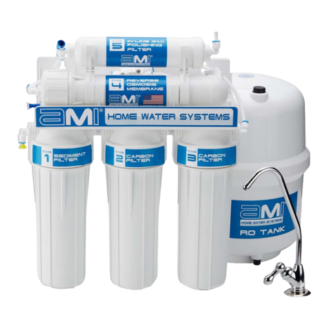
5 Stages of Water Treatment
Stage1: Sediment Filter Cartridge Replace every 3-6 months
The water first passes through is a five micron filter cartridge to remove sediment including dirt, sand, rust, grit,
and other suspended matter from water. This protects the rest of the filtration stages and equipment from
damage and clogging due to buildup of sediment.
Stage 2 & 3: Carbon Block Filter Cartridges Replace every 3-6 months
Next, the water passes through two stages of carbon filters to remove chlorine and objectionable tastes and odors
from water. These filters also protect the membrane from exposure to chlorine, which would irreparably damage
the membrane.
Stage 4: Reverse Osmosis Membrane Replace every 12 months
The RO membrane, the heart of the RO system, substantially reduces the total dissolved solids (TDS) from the
water, including arsenic, barium, cadmium, chromium (hexavalent), chromium (trivalent), copper, turbidity,
fluoride, lead, radium 226/228, and selenium, while washing the rejected contaminants down the drain. The
treated water is directed to the storage tank.
Stage 5: Post Carbon Filter Replace every 3-6 months
The last stage of filtration occurs as the water flows from the storage tank directly before being dispensed from
the faucet. The in-line carbon post filter (also known as polishing filter) removes any remaining tastes or odors
from the water, improving the flavor.
Stage 6: Ultraviolet System Replace Lamp every 12 months
After the final stage of filtration, water is disinfected by passing through Viqua Model VT1 ultraviolet disinfection
system. The UV disinfection system is designed to protect your water from microbiological contaminants.
Notice:
Replacement frequency varies based upon incoming water quality and use patterns.
Generally speaking, filters should be changed when there is a loss of performance
or after an extended period of non-use.
System On/Off Valves
Your RO System is equipped with two on/off ball valves. The system feed valve (to be installed into the cold water supply
line) can be used to turn the water to the system on and off for maintenance without disrupting the water supply to the
sink. The tank valve can also be closed to prevent water in the tank from draining out during maintenance. Both can be
opened by turning counterclockwise, and closed by turning clockwise.
System Feed Valve in
OPEN Position System Feed Valve in
CLOSED Position Tank Valve in
OPEN Position Tank Valve in
CLOSED Position

Installation and Service Manual – Under-the-Counter Point of Use 6 Stage Reverse Osmosis System with Pump & UV
Copyright © 2020 WaterAnywhere.
All Rights Reserved.
Page 2
Table of Contents
About Your RO Water Treatment System.........................................................................................................1
5 Stages of Water Treatment ............................................................................................................................1
System On/Off Valves.......................................................................................................................................1
Table of Contents ...............................................................................................................................................2
Conditions for Operation ...................................................................................................................................3
Warnings .............................................................................................................................................................3
System Flow Diagram ........................................................................................................................................4
Preparing For Installation..................................................................................................................................5
Recommended Tool List: ..................................................................................................................................5
Check Location .................................................................................................................................................5
Assemble Filter Housings onto System Manifold..............................................................................................5
Prepare Tubing .................................................................................................................................................6
Quick Connect Fittings and Tubing Connections ..............................................................................................6
Step 1 - Drill a Hole into the Sink for the Faucet..............................................................................................7
Step 2 - Faucet Installation................................................................................................................................8
Step 3 - Drain Saddle Installation......................................................................................................................9
Step 4 – System Feed Line Installation ..........................................................................................................10
Step 5 – Installing the RO Storage Tank.........................................................................................................11
Additional Point of Use Connection (Optional) .............................................................................................11
System Mounting..............................................................................................................................................12
Turning the System On for the First Time......................................................................................................12
Replacement Parts ...........................................................................................................................................13
System Maintenance........................................................................................................................................14
Membrane Replacement Instructions .............................................................................................................14
Filter Replacement Instructions.......................................................................................................................14
Ultraviolet (UV) System Maintenance .............................................................................................................14
Sanitizing.........................................................................................................................................................17
Troubleshooting Chart.....................................................................................................................................18
UV System Operation Safety...........................................................................................................................19
Pump Troubleshooting ....................................................................................................................................20
Maintenance Schedule and Log…………………………………………………………………………Back Cover

Installation and Service Manual – Under-the-Counter Point of Use 6 Stage Reverse Osmosis System with Pump & UV
Copyright © 2020 WaterAnywhere.
All Rights Reserved.
Page 3
Conditions for Operation
Source Water Supply
Community/Private Non-Chlorinated – or chlorinated as long as the carbon filter is in place
and replaced every 6 months. Chlorine will damage membranes if not
removed properly.
System Pressure 40 psi minimum - 90 psi maximum
Temperature 4º-38º C (40º-100º F)
Maximum Supply TDS Level 1500 ppm (mg/L)
Turbidity <1.0 Net Turbidity (NTU)
Chemical Parameters
Hardness (CaCO3) <175 mg/L (<10 gpg)*
Iron (Fe) <0.1 mg/L
Manganese (Mn) <0.05 mg/L
Hydrogen Sulfide (H2S) 0.00 mg/L
Chlorine (CL2) 0.00 mg/L
pH 4 to 11
*Note that system may operate with higher hardness levels, but the membrane life will be reduced. Use of a
water softener for hard water supplies will increase membrane life and efficiency.
Warnings
Only use this system on potable water supplies. Do not use this system where the
water is microbiologically unsafe or of unknown quality.
Never use hot water or allow the unit to freeze.
Incorrect installation or operation will void the warranty.
Excessive incoming water pressure can cause leaks, flooding and property damage. It
is highly recommended to monitor your home’s incoming water pressure over a period
of 24 hours to determine if a pressure regulator is required.
Manufacturer assumes no responsibility for damages incurred through improper
installation or use of these products.
Ensure that all tubing and fittings used for RO product water are poly material, and not
copper. Due to RO product water being very pure, it can leach the minerals from
copper tubing which will cause a metallic taste in the water or ice and cause the copper
tubing to develop pinhole leaks over time.

Installation and Service Manual – Under-the-Counter Point of Use 6 Stage Reverse Osmosis System with Pump & UV
Copyright © 2020 WaterAnywhere.
All Rights Reserved.
Page 4
SystemFlowDiagram
A Water supply to the first housing
B Water supply to the second housing
C Water supply to the third housing
D Housing with the RO Membrane
E Tank Shut-Off Valve
F Fou
r
-way Valve
G In-Line Cartridge with Activated Carbon
H Flow Restricto
r
I Tank Valve
J Tank
K UV System
L Faucet
1 Clean Water Outlet
2 Pollutants Outlet
3 Water Supply to the 4-way valve from the
elbow connector “OUT” in the third housing
4 Clean water supply to the 4-way valve
through the membrane
5 Water outlet from the valve to the membrane
6 Clean water outlet from the valve to the in-
line cartridge with activated carbon

Installation and Service Manual – Under-the-Counter Point of Use 6 Stage Reverse Osmosis System with Pump & UV
Copyright © 2020 WaterAnywhere.
All Rights Reserved.
Page 5
Preparing For Installation
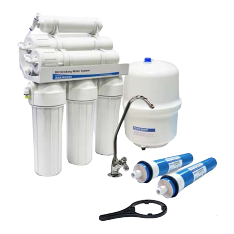
Check the following list of components to ensure that all parts are packed with your system.
RO System
Manifold
A
ssembly
Filter Housing
Sumps
Filter Cartridges
(Packed in Sumps)
Storage Tank
Faucet Kit
Drain Saddle
Feed Adapter Kit
Tank Valve
Filter Wrench
Membrane Wrench
White Tubing
Recommended Tool List:
Have the below tools on hand before beginning installation. These are not included with the system.
Electric drill with ⅛”, ¼" & 7/16” drill bits
1-¼” hole saw bit for faucet opening – appropriate for the surface
you are drilling
½” and
7/16” open-end wrenches (or two adjustable wrenches)
Mounting screws or anchors appropriate for the mounting surface
Phillips screwdriver
Utility knife
Teflon tape (included)
Masking tape or duct tape
CheckLocation
Determine the location for the installation of the RO system. Avoid locations where the system might come
in contact with hot water pipes or other hazards. Electrical outlets are needed for the UV & pump power
supplies. UV Controller should be mounted to the wall (see “System Mounting” section).
Determine the location of the cold water feed line to use for the system supply.
Notice:
Accidentally hooking up the system to the hot water supply line will permanently
damage the membrane (see conditions for operation). To assure you are using the
cold water line, turn on both the hot and cold faucet. After the water is warm to the
touch, feel the pipes under the sink. It will be easy to identify the hot and cold pipes.
Determine the location for the faucet. Check to see that drilling the faucet hole will not damage pipes or
wires running underneath the sink.
Determine the location for the storage tank. A maximum distance from tank to faucet of 15 feet is possible
(additional tubing will be needed). The system will produce a faster flow at the faucet with the shortest
tubing run from tank to faucet.
Assemble Filter Housings onto System Manifold
Remove the plastic wrapping from the filter cartridges and insert each cartridge into a filter sump.
Making sure the o-ring stays seated properly, screw the filter sump onto the appropriate cap. The filters
should be installed in the following order of flow (left to right):
(1) Sediment Filter H-F1005CF (2) Carbon Filter H-F2510AC (3) Carbon Filter H-F2510AC
Check to ensure the sump is tightly threaded onto the housing.

Installation and Service Manual – Under-the-Counter Point of Use 6 Stage Reverse Osmosis System with Pump & UV
Copyright © 2020 WaterAnywhere.
All Rights Reserved.
Page 6
Prepare Tubing
When cutting tube lengths, it is important to ensure the system is
accessible for maintenance. During installation and measuring, it is
recommended to complete all of the tubing connections to the system
with the system in front of the cabinet (before mounting) to allow enough
slack for easy removal of the system for easier maintenance.
Measure and cut (4) lengths of tubing in the appropriate lengths for:
Feed line to system pre-filter inlet
Post filter inlet (tee) to tank
Post filter outlet (elbow) to faucet
Membrane outlet flow restrictor to drain
Quick Connect Fittings and Tubing Connections
To ensure a secure seal using quick connect fittings:
Cut tubing with the end square. An angled cut or distortion of the
tubing will not provide an efficient seal and may cause leaks.
Remove blue locking clip from fitting before installing tubing. Push
down on the fitting collet and remove the plug. Keep the clip. The plug
may be discarded.
Push the tubing into the fitting, to the pipe stop. The collet (gripper)
has teeth which hold the tubing firmly in position while the 'O' Ring
provides a permanent leak proof seal.
Check the Seal: Pull on the tubing to check it is secure. It is good
practice to test the system prior to leaving site and/or before use.
Replace blue locking clip after tubing is installed.
To Disconnect: Ensure system is depressurized before removing
fittings. Push in the collet against the face of the fitting. With the collet
held in this position the tube can be removed. The fitting can then be re-
used.

Installation and Service Manual – Under-the-Counter Point of Use 6 Stage Reverse Osmosis System with Pump & UV
Copyright © 2020 WaterAnywhere.
All Rights Reserved.
Page 7
Step 1 - Drill a Hole into the Sink for the Faucet
Notice:
If your sink is equipped with a pre-drilled 1 ¼” or 1 ½” hole suitable for the faucet
installation, you may skip to step 2.
Notice:
Manufacturer assumes no responsibility for damages resulting from installing faucets
into any surface. It is recommended to use a licensed contractor for this step.
For this, step, you will need:
Masking tape or duct tape
Variable speed drill with ⅛” and 7/16” drill bits
1-¼” hole saw bit for faucet opening – appropriate for the surface you are drilling
Determine the desired location for your RO Faucet
The product water faucet may be installed on any flat surface at least 2” in diameter. Check the underside
of the location for interference. The standard faucet that is supplied with the system requires a ½” diameter
hole. The optional air-gap faucet requires a larger hole of ¾” to allow for the additional tubing connections
required.
Stainless Steel Sinks
Begin by placing a piece of masking tape or duct tape on the determined location where the hole is to be
drilled. Make a small indent to mark the desired drilling location using a center punch. Drill a pilot hole with
a ⅛” metal drill bit. Enlarge the hole using a ¼” metal drill bit, using factory approved method or approved
plumbing practice.
Porcelain/Enamel Sinks or Tile Countertop
Sinks of this type are very easy to damage due to the nature of the materials of construction. A successful
installation into these sinks requires a knowledgeable technician with the proper cutting tools. We strongly
recommend the use of a “Relton” type device. Follow the directions that accompany the tool carefully.

Installation and Service Manual – Under-the-Counter Point of Use 6 Stage Reverse Osmosis System with Pump & UV
Copyright © 2020 WaterAnywhere.
All Rights Reserved.
Page 8
Step 2 - Faucet Installation
For this step, you will need:
Faucet assembly kit included with System
Tubing, cut to the appropriate length
Wrench
Install the faucet onto the
countertop/sink:
Find and identify all of the parts in the faucet bag, as
shown in the diagram.
Add the metal washer (2), and then the rubber seal
(3) onto the threaded nozzle of the faucet (1).
Place the faucet nozzle through the previously drilled
hole in the countertop or sink top, and let it rest on the
sink top.
From the underside of the sink, slide the washers
onto the threaded stem as shown in the diagram.
- (4) & (5) - made of rubber
- (6) - made of metal
Secure the assembly by threading on the locking nut
(7).
Check the orientation and alignment of the faucet and
washers, adjust as necessary, then use a wrench to
tighten the locking nut securely
Notice:
Do not overtighten fittings.
Install the Tubing
Slide the metal nut (10) over the end of the tubing
with the threads facing up.
Add the plastic clamp (9).
Press the plastic insert (8) into the end of the tubing.
Slide the tubing (until it
stops) inside the faucet
nozzle and screw it in by
hand with the nut that was
placed on the tubing earlier
(10).
Connect the other end of
the tubing to the elbow in
the “out” end of the UV
System.

Installation and Service Manual – Under-the-Counter Point of Use 6 Stage Reverse Osmosis System with Pump & UV
Copyright © 2020 WaterAnywhere.
All Rights Reserved.
Page 9
Step 3 - Drain Saddle Installation
Notice:
Some states require the use of an air gap faucet. Check your local plumbing code to
assure compliance.
For this step you will need:
oMasking tape or duct tape
oVariable speed drill w/ ⅛” and ¼" drill bits
oPhillips Screwdriver
oDrain saddle assembly supplied with system
oWhite tubing cut to appropriate length
Select Location for Drain Saddle Installation
Select a location for the drain hole based on the design of the
plumbing. It should be installed above the trap and on the
vertical or horizontal tail piece.
Notice:
Do not install downstream of a garbage
disposal, as this can cause
contamination and system fouling.
Install onto a drain location without a
garbage disposal.
Drill a ¼” Hole in the Drain Pipe
Starting with the ⅛” drill bit, drill a ⅛” hole in the drain pipe.
Use the ¼” drill bit to enlarge the hole. Clean the debris from
the pipe and the hole before continuing.
Notice:
Take extreme caution to not drill through to the other side of the drain pipe.
Install the Drain Clamp
Apply the foam gasket inside the front half of the drain saddle: Punch out
the cut-out hole in the center of the pad, remove the adhesive backing, and
adhere to the inside of the drain saddle, ensuring the holes are aligned.
Place one half of the plastic drain saddle assembly on each side of the
drain pipe with the fitting, and clamp loosely using the nuts and bolts
included.
Align the hole drilled in the drain pipe with the hole in the drain saddle. A
drill bit or other long narrow object may be used to help align correctly.
Use Phillips screwdriver to tighten the clamp. Avoid over-tightening.
Connect Drain Line to RO System Reject Line
Insert tubing to the pipe stop in the quick connect fitting on the drain line and
check the seal.
Connect the other end of the tubing to the flow restrictor outlet coming from the
membrane brine port.

Installation and Service Manual – Under-the-Counter Point of Use 6 Stage Reverse Osmosis System with Pump & UV
Copyright © 2020 WaterAnywhere.
All Rights Reserved.
Page 10
Step 4 – System Feed Line Installation
For this step you will need:
½” and
7/16” open-end wrenches (or two adjustable wrenches)
Teflon Tape
Feed Adapter & Ball Valve Kit
Tubing
Locate and Turn Off the Cold Water Supply
Locate the valve in the cold water feed line you use for the supply.
Notice:
Accidentally hooking up the system to the hot water supply line will permanently
damage the membrane (see conditions for operation). To assure you are using the
cold water line, turn on both the hot and cold faucet. After the water is warm to the
touch, feel the pipes under the sink. It will be easy to identify the hot and cold pipes.
Close the cold water valve.
Turn on the sink faucet to drain water and relieve pressure from the lines.
If no shut off valve is located under the sink, or if water continues to come out of the faucet, turn off the
main supply at the entry to the house, then turn on the sink faucet to drain water and relieve pressure from
the lines.
Assemble the Ball Valve & Adapter Kit
Use Teflon tape to wrap the threads of the ball valve – approximately 3 wraps.
Screw the ball valve into the adapter.
Install the Feed Adapter into the Cold Water Supply
Wrap the slip joint adapter with Teflon tape, approximately 3 wraps.
For Flex Line: Loosen nut and separate cold water riser tube from faucet
shank. Gently bend riser rube so that slip joint fits onto faucet shank. Make
sure the flat washer is on top and the cone washer is on the bottom.
Reinstall riser tubes onto slip joint adapter and tighten.
For Solid Copper Riser Tube: Same procedure as flex tubing except you
must cut a piece of the riser tube about ¾” to 1” so the slip joint adapter can
fit between faucet and riser tube.
Connect the Feed Line Tubing
Unscrew the nut from the ball valve. Slide the nut onto the tubing, threaded sides facing the end of the
tubing. Feed the nipple on the ball valve into the
tubing, pushing the tubing until it slides over the lip.
Slide the nut to the threads on the ball valve, and
tighten the nut down over the tubing. Use a wrench to
tighten ¼ turn past finger-tight.
Connect the other end of the tubing to the feed port on
the RO System.

Installation and Service Manual – Under-the-Counter Point of Use 6 Stage Reverse Osmosis System with Pump & UV
Copyright © 2020 WaterAnywhere.
All Rights Reserved.
Page 11
Step 5 – Installing the RO Storage Tank
For this step you will need:
Storage Tank
Tank Valve
Tubing
Notice:
Do not tamper with the air valve on the low side of the storage tank. It has been
factory charged to 8psi and covered with a black cap.
Install the Tank Valve & Tubing
Remove the blue cap on top of the tank to expose the
threaded in/out connection. Connect the tank ball valve
by threading onto the fitting. Do not over-tighten.
Notice:
Do not add teflon tape to the tank
fitting. This will prevent seals from
engaging and may cause leaking.
Insert the tubing into the quick connect fitting on the ball
valve.
Connect the other end of the tubing to the inlet tee of
the post-carbon filter on the RO system.
Additional Point of Use Connection (Optional)
Notice:
Ensure that all tubing and fittings used for RO product water are poly material, and not
copper. Due to RO product water being very pure, it can leach the minerals from
copper tubing which will cause a metallic taste in the water or ice and cause the
copper tubing to develop pinhole leaks over time.
An additional connection may be made to other equipment such as an icemaker, refrigerator, coffeemaker, or
other equipment. This requires an additional tee fitting and extra tubing. It is also strongly recommended to
install an in-line ball valve between the RO system and the equipment, to be closed during startup and
maintenance.
Suggested Parts
¼” Union Tee ¼” Tubing (10 Feet) ¼” In-Line Ball Valve
Part Number: PI0208S Part Number: TUBE-10FT-14-WH Part Number: PPSV040808
W
Installation
Cut tubing between the faucet and the outlet of the post-filter. Insert the line into both branches of the tee.
Run line from the stem of the tee to the equipment and connect according to manufacturer’s instructions.
Install the ball valve in an accessible location on the line by cutting the line and inserting the tubing into
both sides of the ball valve.

Installation and Service Manual – Under-the-Counter Point of Use 6 Stage Reverse Osmosis System with Pump & UV
Copyright © 2020 WaterAnywhere.
All Rights Reserved.
Page 12
SystemMounting
Wall mounting is recommended for this system. Dry wall anchors and screws may be necessary (not included
with the system).
Mark screw locations at the desired positions. Use the two holes on the back of the RO System mounting
bracket for marker guides.
Screw the screws into the mounting wall on the marked positions. Use an anchoring device appropriate for
the type of material you are screwing into.
Hang the purification system onto the screws by the holes on the back of the unit.
Mount the UV controller horizontally to the wall, near the UV chamber.
Ideally place the controller above the chamber and away from any
water connection point, to prevent any water from potentially leaking
onto the controller by means of a leak at a connection point or a
“sweating” system. Make sure you allow for a “drip-loop” as shown in
the following diagram on the UV lamp, UV sensor, and power cord,
again, to prevent any water from potentially entering the controller.
Turning the System On for the First Time
Make sure all water supply and drain line connections are secure and free from leaks.
Plug the system into the ground fault interrupter and check controller to ensure the system is operating
properly. The controller should illuminate without any alarms. Wait 5 minutes for UV lamp to reach full power.
Slowly turn the feed valve counterclockwise until fully open (the handle should be in line with the tubing as it
enters the connection). Check the stem seal for leakage. If necessary, tighten stem nut lightly.
Plug the pump transformer cord into an electrical outlet.
Turn storage tank valve one quarter turn counterclockwise to open the valve (the handle should be in line with
the tubing as it enters the connection).
Open the product water faucet and let the water flow until all the air has been expelled from the system. This
will take about an hour.
Close the product water faucet. In 30 minutes, check the system and connections for leaks and correct if
necessary.
Do Not Use the First Two Reservoirs of Water
Allow the reservoir to fill for 4-6 hours. Dispense this water to drain. This process
removes the factory installed sanitizing solution from the entire system and sends it to
the drain. Repeat this process one more time. Allow the tank to fill for 4-6 hours and
dispense this water to the drain. Do not drink this water!
Notice:
Air bubbles may be present in the product water after initial system startup, causing
a milky color in the water. This is normal and safe to drink. The air bubbles will
disappear within a few days of regular use.
Notice:
Check back frequently in the first 24 hours to ensure no leaking has occurred.
Notice:
When there is no flow, the water in the UV cell will become warm, as the UV lamp is
always on. To remedy this, run cold water for a minute to flush out the warm water.

Installation and Service Manual – Under-the-Counter Point of Use 6 Stage Reverse Osmosis System with Pump & UV
Copyright © 2020 WaterAnywhere.
All Rights Reserved.
Page 13
Replacement Parts
Sediment Pre-Filter,
5 Micron.
Stage 1
Model: H-F1005CF
Qty. 1 Per System
Replace every 3-6 months
Carbon Pre-Filter,
Extruded Carbon
Stage 2 & 3
Model: H-F2510AC
Qty. 2 Per System
Replace every 3-6 months
Replacement Filter Kits:
RFK-5: Pre & Post Filters
RFK-5-PRE: Pre-Filters Only
RFK-5-50 (50 gpd)
RFK-5-100 (100 gpd)
One complete set of prefilters, post
filter, and membrane.
See back cover for replace schedule.
Membrane Element
Stage 4
Model:
50 GPD: 1812-50 -RO
100 GPD: 1812-100-RO
Qty. 1 Per System
Replace ever
y
12 months
Carbon Post-Filter,
GAC Inline
Stage 5
Model: H-F1032-43A
Qty. 1 Per System
Replace every 3-6 months
UV System Consumables - Stage 6
Lamp Model: S212RL
Replace every 12 months
Quartz Sleev Model: QS-212
Replace as-needed during lamp change
Part Image
8851-2J03-B423
Booster Pump
TACS-114-48
Pump Power Supply
PSW240
Shut-Off Switch
LPS340G
Low Pressure Switch
H-H14FWWA
Filter Housing
Standard 10”
White, ¼” FNPT
PV2012PME
Membrane Housing
⅛” FNPT
H-S3200PW
Storage Tank
3.2 gallon
H-R2068QC
50 GPD Flow Restrictor
H-R1000QC
100 GPD Flow Restricto
r
Part Image
OR-212
UV Lamp O-Ring
RN-001
Retaining Nut for UV
FXFCH5
Faucet, Non-Airgap,
Long-Reach
H-S3200TV
Tank Shut-Off Valve
H-V1009
Feed Valve and
Adapter
H-V1050W-QC
Auto Shut-Off Valve
H-D3000M
Drain Saddle
H-C9200FWWA
Wrench for Filter
Housing
OR-H10FWWA-SET
O-Ring Set for Filter
Housing.
Part Image
H-J2021KW
Clip, Membrane
Housing to In-line Filte
r
H-J2025PW
Clip, Membrane
Housing to Bracket
TUBE-10FT-14-WH
White Tubing
10 foot pack
F-4MBT44QC
¼” Male to ¼”QC
Branch Tee (for post
filter inlet)
PI480822S
Elbow Fitting
¼” MNPT × ¼” QC
PI480821S
Elbow Fitting
⅛” MNPT × ¼” QC
H-V1003
Check Valve, installed
in ¼” Elbow
(membrane permeate)
H-B2044W
Mounting Bracket

Installation and Service Manual – Under-the-Counter Point of Use 6 Stage Reverse Osmosis System with Pump & UV
Copyright © 2020 WaterAnywhere.
All Rights Reserved.
Page 14
System Maintenance
Notice:
Unplug the Pump & UV before perorming any maintenance to the system.
Notice:
If your RO system is connected to an icemaker or other equipment, you must turn off
the connection to the equipment before performing any maintenance.
Membrane Replacement Instructions
The membrane should be replaced every 1-2 years, depending on the water quality.
Before starting, shut off the cold water supply to the unit and unplug the UV system. Lift the handle on the
faucet to drain out the storage tank completely and allow the system to stand for 10 minutes in order to fully
decompress the tank. Leave the faucet open until the membrane change is complete.
1. Unscrew the fitting to the cap of the membrane housing. Use the membrane wrench if the cap is too tight.
2. Using pliers, pull out the old membrane from the housing.
3. Remove the new membrane from its bag.
4. Insert the membrane in the housing in the same direction as the old membrane.
5. Push the membrane firmly into the housing until it seats on the far end.
6. Screw the housing cap back on, making sure the o-ring is positioned correctly.
7. Screw the fitting (with tubing) back onto the housing.
8. The system is ready. Turn on the water supply. Check for any leaks.
9. Drain the first two tanks of water before drinking.
Filter Replacement Instructions
All pre and post-filters should be replaced every 3-6 months.
Before starting, shut off cold water supply to unit and unplug the UV system. Lift the handle on the faucet to
drain out the storage tank completely and allow the system to stand for 10 minutes in order to fully decompress
the tank, reserving some of the RO water to use to rinse the filter housings. Leave the faucet open until the
filter change is complete.
1. Remove pre-filters from filter housings. Use a filter wrench if the housings are too tight.
2. Discard used filters, but save o-rings for re-use.
3. Clean inside of all housings with a mild soap solution, and then rinse with RO water.
4. Lubricate the o-ring and replace in filter housing.
5. Insert the new filters into the appropriate housings and replace the housings onto the system.
6. Disconnect the post-filter by removing the fittings on either end. Replace with new post-filter and re-use
the existing fittings. (Feed end tee is connected by a short length of tubing, remove this and use to connect to new filter.)
7. Follow the normal Start-up Procedures. (Drain the first tank of water after changing the filters before
drinking.)
Ultraviolet (UV) System Maintenance
Warning!
Always disconnect power before performing any work on the disinfection system.
Always shut-off water flow and release water pressure before servicing.
Regularly inspect your disinfection system to ensure that the power indicators are on.
Replace the UV lamp annually (or biennially if seasonal home use) to ensure maximum
disinfection.
Always unplug the UV system and drain the chamber when closing a seasonal home or
leaving the unit in an area subject to freezing temperatures.

Installation and Service Manual – Under-the-Counter Point of Use 6 Stage Reverse Osmosis System with Pump & UV
Copyright © 2020 WaterAnywhere.
All Rights Reserved.
Page 15
Replacing UV Lamp
UV lamps should be replaced every 12 months. The quartz sleeve can be re-used, but is very fragile. It is
recommended to have a spare quartz sleeve on hand in case it is broken during the lamp change.
Close the system feed valve and the
tank valve to cut off the water supply.
Turn on the faucet to release any
pressure in the lines. Disconnect
main power source and allow the unit
to cool for 10 minutes
Using a small container to drain
the water inside the UV and
tubing remove the inlet and outlet
tubing to the UV. Remove the
UV from the clips on the system.
Holding the chamber vertically,
remove the lamp connector by
squeezing the plastic locking
tabs on the side of the
connector.
Remove the UV lamp in upward
direction from the UV chamber and
lamp connector base.
Hold the UV lamp at the ceramic
ends.
Insert the new UV lamp fully into
the UV chamber leaving about
two inches of the UV lamp
protruding from the UV chamber.
Attach the connector to the UV
lamp and note that the
connector will only allow correct
installation in one position.
Push the lamp connector against
lamp connector base together until
an audible click is heard.
Redommnect the inlet and outlet
tubing. Restore power and
repressurize the system to check for
leaks.
NOTICE:
Refer to www.lamprecycle.org for UV lamp disposal.
Do not use water during replacement of UV lamp.
As UV does not provide a chemical disinfection residual, it is
imperative that the entire distribution system located after the
UV be chemically disinfected to ensure that the plumbing
system is free from any bacteriological contaminants. The
disinfection process must be performed immediately after the
UV unit is installed and repeated thereafter whenever the UV
is shut down for service, without power, or inoperative for any
reason.

Installation and Service Manual – Under-the-Counter Point of Use 6 Stage Reverse Osmosis System with Pump & UV
Copyright © 2020 WaterAnywhere.
All Rights Reserved.
Page 16
Cleaning and Replacing Quartz Sleeve
Note: Minerals in the water slowly form a coating on the quartz sleeve. This coating must be removed because
it reduces the amount of UV light reaching the water, thereby reducing disinfection performance. If the sleeve
cannot be cleaned, it must be replaced.
Prerequisites:
Shut off water supply and drain the line.
Place a small pail under the unit to catch any spills.
Remove the UV lamp. Refer to Previous Section.
Remove the bottom retaining nut,
floating spring, and Oring.
Remove the top retaining nut and
O-ring.
Carefully remove O-ring adhering
to the sleeve. Remove the quartz
sleeve.
Clean the quartz sleeve with a
cloth soaked in CLR, vinegar or
some other mild acid and then
rinse with water.
Note: If sleeve cannot be
completely cleaned or it is
scratched or cracked, then replace
the sleeve.
Reinstall the quartz sleeve in the
UV chamber allowing the sleeve
to protrude at equal distance on
both ends of the UV chamber.
Reinstall the top and bottom
retaining nuts, floating spring, and
O-rings respectively.
When service is complete,
assemble the prerequisites in the
reverse order of disassembly.
Push the lamp connector against
lamp connector base together until
an audible click is heard.
Plug in controller and verify the
POWER-ON LED display is
illuminated.
Re-pressurize the system to check
for leaks.
Notes:
1) After replacing the UV lamp or
quartz sleeve, perform the disinfection
procedure.
2) If the system is put on a temporary
by-pass or if it becomes contaminated
after the disinfection system, it is
necessary to shock the system with
household bleach for a full 20 minutes
before resuming the use of the water.

Installation and Service Manual – Under-the-Counter Point of Use 6 Stage Reverse Osmosis System with Pump & UV
Copyright © 2020 WaterAnywhere.
All Rights Reserved.
Page 17
Sanitizing
We recommend sanitizing the system at least once a year. This can be done while changing your filters. Shut
down the system. If you have an icemaker hook-up installed, be sure the ball valve in the line to the
refrigerator is in the closed position during this procedure. Open the faucet to drain the system, including the
tank. Remove the pre-filter cartridges and RO Membrane from the system, leaving the old post-filter cartridge
in place. Wash the internal filter housing & membrane housing areas with warm soapy water and rinse well to
remove the soap. Pour about ¼ teaspoon of Hydrogen Peroxide or household bleach into each filter housing
and replace housings on the RO system. Open the feed water valve and open the RO faucet until water flows
freely from the spout. Close the faucet and hold the solution in the system for a minimum of 10 minutes.
Drain the tank completely, close the faucet to allow tank to fill again, and then drain again. Replace filters and
membrane as indicated in the replacement instructions. The post filter should be changed after sanitizing the
system. Repeat the “Turning the System On for the First Time” procedure (page 13.)
*Note: It is recommended to chemically disinfect the entire distribution system located after the UV. To
ensure water being routed to external equipment is microbiologically safe and does not contaminate the water
in the system, this equipment and leading plumbing must be disinfected according to manufacturer’s
instructions.

Installation and Service Manual – Under-the-Counter Point of Use 6 Stage Reverse Osmosis System with Pump & UV
Copyright © 2020 WaterAnywhere.
All Rights Reserved.
Page 18
Troubleshooting Chart
Symptom Possible Cause Remedy
No water in the storage
tank
Filter Cartridges have failed. Replace filter cartridges as indicated in
maintenance section.
Cartridges are out of
sequence.
Install cartridges in proper sequence as
indicated in system components.
Cartridges are upside-down. Install carbon block filter right-side-up as
indicated on the filter.
No pressure in storage tank. Check pressure with pressure gauge. Refill or
reduce pressure to max 8 psi. Note: Tank
must be empty of water when checking the air
pressure.
Automatic shut-off valve
malfunctioning.
Check lines to valve for correct hook-up and
check water running into the drain. Replace if
necessary.
Kinked lines. Straighten lines if necessary.
Getting low flow Incoming water pressure too
low.
Check source of feedwater (city water, well
water, etc.) for pressure. A booster pump may
be required.
Change in feedwater
temperature.
The reverse osmosis membrane used in your
unit is rated at 77ºF and 60psi. Water
production will decrease approximately 1.5%
for each degree that your incoming water is
below 77ºF. It may be necessary to change to
a higher flow membrane (and flow restrictor).
Storage tank pressure is too
low.
Check pressure with gauge and refill to
maximum 8 psi. Note: Tank must be empty of
water when checking the air pressure.
Filters are clogged. Replace Filters.
Water leakage at filter
bowls
Filter bowls are loose. Retighten.
Burr on edge of filter bowl. Remove burr with emery cloth or sand paper.
O-Ring in filter bowls is
missing, damaged, or not
sealed properly
Replace or position correctly.
Water backing up to air gap
in faucet (Systems w/ air
gap faucets only)
Line is clogged. Clean out the line.
Line is too long. Must be as short and straight as possible.
Drain line is clogged. Disconnect 3/8” dia. Line and clean out with
probe or by flushing.
Faucet spout is dripping Handle sticking or worn. Replace the faucet
Milky colored water Air in the system Air in the system is normal after startup of the
RO. Water should lose the milky look within a
few days of normal usage.
Warm Water Water Standing in UV System When there is no flow, the water in the cell will
become warm, as the UV lamp is always on.
Simply run the faucet until water coming out is
cool.

Installation and Service Manual – Under-the-Counter Point of Use 6 Stage Reverse Osmosis System with Pump & UV
Copyright © 2020 WaterAnywhere.
All Rights Reserved.
Page 19
UV System Operation Safety
DANGER
Failure to follow these instructions will result in serious injury or death.
Electric Shock: To avoid possible electric shock, special care should be taken since water is present near the electrical equipment. Unless a
situation is encountered that is explicitly addressed by the provided maintenance and troubleshooting sections, do not attempt repairs yourself,
refer to an authorized service facility.
GROUNDING: This product must be grounded. If it should malfunction or breakdown, grounding provides a path of least resistance for electric
current to reduce the risk of electrical shock. This system is equipped with a cord having an equipment-grounding conductor and a grounding plug.
The plug must be plugged into an appropriate outlet that is properly installed and grounded in accordance with all local codes and ordinances.
Improper connection of the equipment-grounding conductor can result in a risk of electrocution. Check with a qualified electrician or service
personnel if you are in doubt as to whether the outlet is properly grounded. Do not modify the plug provided with this system – if it does not fit in the
outlet, have a proper outlet installed by a qualified electrician. Do not use any type of adapter with this system.
GROUND FAULT CIRCUIT INTERRUPTER PROTECTION: To comply with the National Electrical Code (NFPA 70) and to provide additional
protection from the risk of electric shock, this system should only be connected to a properly grounded, grounding-type controller receptacle that is
protected by a Ground Fault Circuit Interrupter (GFCI) or to a residual current device (RCD) having a rated residual operating current not exceeding
30 mA. Inspect operation of GFCI as per manufacturer’s suggested maintenance schedule.
DO NOT operate the disinfection system if it has a damaged cord or plug, if it is malfunctioning or if it has been dropped or damaged in any
manner.
DO NOT use this disinfection system for other than intended use (potable water applications). The use of attachments not recommended or sold by
the manufacturer / distributor may cause an unsafe condition.
DO NOT install this disinfection system where it will be exposed to the weather or to temperatures below freezing.
DO NOT store this disinfection system where it will be exposed to the weather.
DO NOT store this disinfection system where it will be exposed to temperatures below freezing unless all water has been drained from it and the
water supply has been disconnected.
WARNING
During extended periods of no water flow, the water in your chamber can become very hot (Approx. 60 °C) and potentially lead to scalding. It is
recommended to run your water until this hot water has been purged from your chamber. Do not allow water to contact your skin during this time.
Do not pass water through the UV system for a minimum of 5 minutes after applying power (including after power interruptions) to avoid passing
under-treated water that may, in rare instances, pose health hazards.
This system contains a UV Lamp. Do not operate the UV Lamp when it is removed from the chamber. Unintended use or damage of the system
may result in the exposure of dangerous UV radiation. UV radiation may, even in little doses, cause harm to the eyes and skin.
Changes or modifications made to this system without the consent of the manufacturer could render the system unsafe for operation and may void
the manufacturer's warranty
PROP 65 WARNING: This product can expose you to chemicals including phthalates, which is known to the state of California to cause cancer,
and mercury, which is known to the State of California
to cause birth defects or other reproductive harm. For more information go to
www.P65Warnings.ca.gov.
CAUTION
Failure to follow these instructions could result in minor or moderate injury.
Carefully examine the disinfection system after installation. It should not be plugged in if there is water on parts not intended to be wet such as, the
controller or lamp connector.
Due to thermal expansion concerns and potential material degradation due to UV exposer, it is recommended to use metal fittings and at least 10”
of copper pipe on the outlet of your UV chamber.
Hg EXPOSURE: The UV lamp contains mercury. If the lamp breaks, then avoid inhalation or ingestion of the debris and avoid exposure to eyes
and skin. Never use a vacuum cleaner to clean up a broken lamp as this may scatter the spilled mercury. Obey local regulations and guidelines for
the removal and disposal of mercury waste.
NOTICE
The UV lamp inside the disinfection system is rated at an effective life of approximately 9000 hours. To ensure continuous protection, replace the
UV lamp annually.
The UV system is not to be used or played with by children. Persons with reduced physical, sensory or mental capabilities, or lack of experience
and knowledge, are also not to handle the UV system unless they have been given supervision or instruction.
EXTENSION CORDS: If an extension cord is necessary, use only 3-wire extension cords that have 3-prong grounding-type plugs and 3-pole cord
connectors that accept the plug from this system. Use only extension cords that are intended for outdoor use. Use only extension cords having an
electrical rating not less than the rating of the system. A cord rated for less amperes or watts than this system rating may overheat. Exercise
caution when arranging the cord so that it will not be tripped over or pulled. Do not use damaged extension cords. Examine extension cord before
using and replace if damaged. Do not abuse extension cord. Keep extension cord away from heat and sharp edges. Always disconnect the
extension cord from the receptacle before disconnecting this system from the extension cord. Never yank cord to pull plug from outlet. Always
grasp the plug and pull to disconnect.
If the supply cord is damaged, it must be replaced by a special cord or assembly available from the manufacturer or its service agent.
SYSTEM PROTECTION: To protect your Controller, a UL1449 certified (or equivalent) transient voltage surge suppressor is strongly
recommended.
The UV lamp in this system conforms to the applicable provisions of the Code of Federal Regulations (CFR) requirements including, Title 21,
Chapter 1, Subchapter J, Radiological Health.
Read and understand the Owner’s Manual before operating and performing any maintenance on this equipment.
This manual suits for next models
1
Table of contents
Other Wateranywhere Water Filtration System manuals
Popular Water Filtration System manuals by other brands

Vestergaard
Vestergaard LifeStraw PEAK Series instructions

CSI
CSI Duplex SD48 Installation & operation manual

AQUAPHOR
AQUAPHOR ECO PRO Operation manual

ENQUATICS
ENQUATICS AquaMaster Solar AquaAir Ultra 1 owner's manual

AquaTools
AquaTools Filter Tank Kit manual

Kohler
Kohler K-200 Installation and care guide

Elkay
Elkay EFC1150D-A Installation & user manual

amiad
amiad SAF-1500 Installation, operation and maintenance instructions

Hayward
Hayward SwimClear C200SC owner's manual

Winterhalter
Winterhalter Gastronom RoMatik 150 installation instructions

WaterClinic
WaterClinic LAL-267 user manual

ECOPERLA
ECOPERLA PROFINE POU 3 user manual