Waterax MARK-3 User manual

USER INSTRUCTIONS
1
12/2014
03/2018
1
MARK-3® DIS Digital Ignition Solution
Overview:
WATERAX offers a conversion kit Digital Ignition Solution (DIS) for users that want to convert a MARK-3®from breaker
points and mechanical cut-out switch to the upgraded electronic ignition and Digital Overspeed Switch systems. These
instructions will guide you through the conversion process.
Parts Breakdown:
Figure 1: Digital Ignition Solution (DIS) (600556)
Tools and Materials Required:
To complete the installation, you will require the following tools:
ID
ITEM NO
DESCRIPTION
QTY
1
600154
R-929 FLYWHEEL HOLDING TOOL, PLATED STEEL
1
2
701159
PISTON LOCKING TOOL FOR 185CC
1
3
700723
R-927 PULLER - MAGNETO (M38 X 1.5)
1
4
701158
JIG FOR DOS BRACKET DRILLING
1
5
801117
DRILL BIT #30 HIGH SPEED STEEL 2-3/4"LG
1
6
801118
TAP M4X.7 D4 SPRIAL POINT PLUG HIGH SPEED STEEL
1
7
801146
CDI IGNITION TIMING ADJUSTMENT TOOL
1
8
801162
DIS - FRAME DRILLING TOOL
1
Figure 2: Special tools for conversion (available from WATERAX)
ID
ITEM NO
DESCRIPTION
QTY
-
600556
DIS MK-3 CONVERSION KIT UPG TO CDI / DOS
1
1
600125
B-7592 ELECTRONIC IGNITION BOX ASSY
1
2
701109
R-668E MAGNETO FOR 185CC
1
3
800073
R-661-CDI STATOR, COIL/ARMATURE ASSEMBLY
1
4
800544
R-150 NUT M6X1.0 HEX FUJI LOCK ZINC
1
5
800408
B-5562-18 CLAMP PLASTIC COATED 9/16" ID
1
6
700593
B-6289-1 DOS PRODUCTION UNIT
1
7
700616
B-6289-2 DOS MK-3 BRACKET
1
8
800443
B-6289-3 SCREW M4X0.7X35 PHILLIPS CHEESE HEAD ZINC
2
9
800402
B-6289-4 SCREW M4X0.7X8 PHILLIPS RAISED CHEESE ZINC
2
10
800413
B-6289-5 SCREW M4X0.7X8 PHILLIPS FLAT ZINC
1
11
800400
B-6289-6 LOCKWASHER M4 EXTERNAL TOOTH ZINC
4
-
801116
CABLE TIE 4" NYLON BLACK
3
-
701161
USER INST DIGITAL IGNITION SOLUTION DIS
1

USER INSTRUCTIONS
2
12/2014
03/2018
2
Figure 3: Required tools for conversion
DESCRIPTION
QTY
TORQUE WRENCH
1
13 MM WRENCH
1
10 MM WRENCH
4
7/16” WRENCH
3
13 MM SOCKET
1
10 MM SOCKET
1
7/16” SOCKET
1
17 MM SOCKET
1
RATCHET WRENCH
1
CUTTER
1
FLAT SCREWDRIVER
1
PHILLIPS SCREWDRIVER
1
NEEDLE NOSE PLIERS
1
17/64” DRILL BIT
1
VARIABLE SPEED ELECTRIC DRILL
1
M4X0.7 TAP
1
#30 DRILL BIT
TAPPING LUBRICANT
1
PENCIL OR MARKER (IF NOT EQUIPPED WITH DOS DRILLING JIG)
1
CENTER PUNCH (IF NOT EQUIPPED WITH DOS DRILLING JIG)
1
THREAD LOCKER LOCTITE 243 OR EQUIVALENT
-
THREAD LOCKER LOCTITE 648 OR EQUIVALENT
-
RTV SILICONE SEALANT LOCTITE 5910 OR EQUIVALENT
-

USER INSTRUCTIONS
3
12/2014
03/2018
3
Flywheel (magneto housing):
On very old engines, the flywheel may need to be replaced in order for the DIS and CDI to be correctly timed. On these older
engines, the flywheel magneto mounting stud hole location differs from the newer flywheel.
To differentiate between old and new flywheel, locate the center hub. Older flywheels do not have a recess/step on the
center hub; new flywheels have a recess/step.
Engines that have a serial number below 2776900 will require a newer flywheel (600534); failure to replace the flywheel will
lead to incorrect timing and kickbacks during starting.
Difference between old and more recent flywheels: different magneto mounting stud location.
Old flywheel from engine with serial # below 2776900
Newer flywheel (item no 600534)
Old flywheel: no recess on center hub
Newer flywheel: recess/step on center hub
117.5°
125°
117.5°
117.5°
117.5°
125°
1
2
3
1
2
3
Recess

USER INSTRUCTIONS
4
12/2014
03/2018
4
Procedures:
1. Remove the 12-16
pump end.
2. Remove the fuel
connection and
disconnect the fuel line
from the carburetor.
3. On the carburetor,
rotate the fuel strainer
cover by 180 degrees
from position A to B
(see picture).
Position A
Position B
4. Remove the frame.
5. Use the Drilling Jig to
drill two 17/64” holes
on the right leg (see
images). If not
equipped with tool use
the hole pattern
provided. The CDI box
assembly will be
mounted on the left
and the fuel connection
will move to the right.
6. Remove the ON/OFF
switch and disconnect
the cut-out switch wire.
Discard.
7. Remove the ignition
cable clamp (#10).
8. Remove the fan cowl.
9. Uninstall and discard
the mechanical cut-out
switch and grommets.
10.Remove the pulley and
gasket.
11.If equipped with an
aluminum fan, use the
fan/flywheel holding
tool R-929 and remove
the nut (R-303) that
locks the flywheel
assembly onto the
crankshaft.

USER INSTRUCTIONS
5
12/2014
03/2018
5
12.Using the fan/flywheel
holding tool (R-929),
the flywheel assembly
puller (R-927) and an
adjustable wrench,
remove the flywheel
assembly.
13.NOTE: If equipped with
a thermoplastic fan,
use piston locking tool
701159 instead of R-
929.
Screw tool onto the
cylinder head and
rotate crankshaft until
the piston reaches the
tip to lock the shaft
rotation. 701159 can
be used with both fans.
14.Remove the point
magneto by removing
the three nuts. Discard.
If the magneto is stuck
on the backing plate, it
can be pried off with a
soft hammer and a flat
screw driver. Be
careful not to damage
the fan.
Point magneto
New magneto for CDI
15.Install the new
magneto for CDI using
thread locker Loctite
648 or equivalent.
Tightening torque for
the three nuts: 8-10
Nm.
Loctite 648
16.Remove the point
stator assembly and
replace with the CDI
stator assembly.
Discard point stator.
17.To position the stator,
remove labyrinth ring
and install ignition
timing adjustment tool
801146. Turn stator
clockwise until coil
rests on adjustment
tool. Tighten the three
screws with flat and
lock washers.
Point stator assembly
CDI stator assembly
Nuts (3X)

USER INSTRUCTIONS
6
12/2014
03/2018
6
Tightening torque: 2.5-
3 Nm. Be careful not to
squeeze/pinch the
green wire.
18.If you are not equipped
with the timing
adjustment tool, fit the
stator plate so that the
oblong holes are
centered with the
crankcase threaded
holes; then rotate the
stator plate 1-1.5 mm
counter-clockwise and
tighten the three
screws. Refer to the
MK-3 Service Manual
for dynamic ignition
verification procedures.
Timing adjustment tool
Stator plate adjustment, 1-1.5 mm CCW
Coil resting on tool
19.First pass the green
wire through the
crankcase hole and
then through the
grommet. Install the
grommet on the
crankcase.
20.Pull the green wire
through the grommet
and apply a dab of
RTV silicone sealant.
21.Install the flywheel
assembly. Ensure that
the key is properly
installed. Apply Loctite
243 on the hex nut (R-
303) and tighten using
the fan/flywheel
holding tool (R-929).
Tightening torque: 45-
50 Nm.
22.Install the gasket pulley
and pulley.

USER INSTRUCTIONS
7
12/2014
03/2018
7
23.To install the DOS,
three holes will need to
be drilled and tapped
on the side of the fan
cowl.
24.If you’re using the DOS
bracket drilling jig,
install it on the top 8
mm hole and lock it in
place. Drill the three
holes with a #30 drill
bit.
25.Carefully tap all three
holes with an M4x0.7
tap. Important: use
tapping lubricant.
Fan cowl before drilling of 3 holes
Tapping lubricant
Drilling jig
26.If you are not equipped
with the drilling jig, you
can use the bracket to
position the holes. To
correctly position the
bracket and prevent
any interference, install
the DOS on the
bracket. Position the
assembly on the side
of fan cowl and ensure
that:
•There is no
interference with the
carburetor shroud;
•There is no
interference with the
spark plug cover;
•The bracket lays flat
on the fan cowl (be
careful of the radius
on the fan cowl).
27.Mark the holes with a
center punch.
28.Remove the fan cowl.
Drill and tap.
8 mm hole

USER INSTRUCTIONS
8
12/2014
03/2018
8
29.Install the fan cowl. Do
not install the top lock
nut, air filter side. It will
be used as a ground at
a later step.
30.Install the DOS bracket
using the three 8 mm
long screws and two
tooth lock washers.
31.Install the DOS using
the two 35 mm long
screws and two tooth
lock washers. Ensure
that the DOS is firmly
mounted on the
bracket to ensure
proper ground contact.
32.Install the electronic
ignition box assembly
and the fuel
connection.
33.Install the frame.
Grounding
stud

USER INSTRUCTIONS
9
12/2014
03/2018
9
34.Connect the green wire
from the stator in the
second terminal from
the right.
35.Connect the red wire
from the DOS on the
far-right terminal.
36.Install the ground wire
(red) coming from the
CDI module on the fan
cowl grounding stud.
37.Install the split loom.
38.Install the plastic-
coated clamp and
tighten the lock nut.
39.Install the ignition cable
clamp.
40.Connect the ignition
wire to the spark plug.
41.Secure the wiring with
cable ties.
42.Install the spark plug
cover.
43.Install the pump end.

USER INSTRUCTIONS
10
12/2014
03/2018
10
Impact on Field Use:
Below are the minor changes to the operation of the MARK-3®equipped with the DOS.
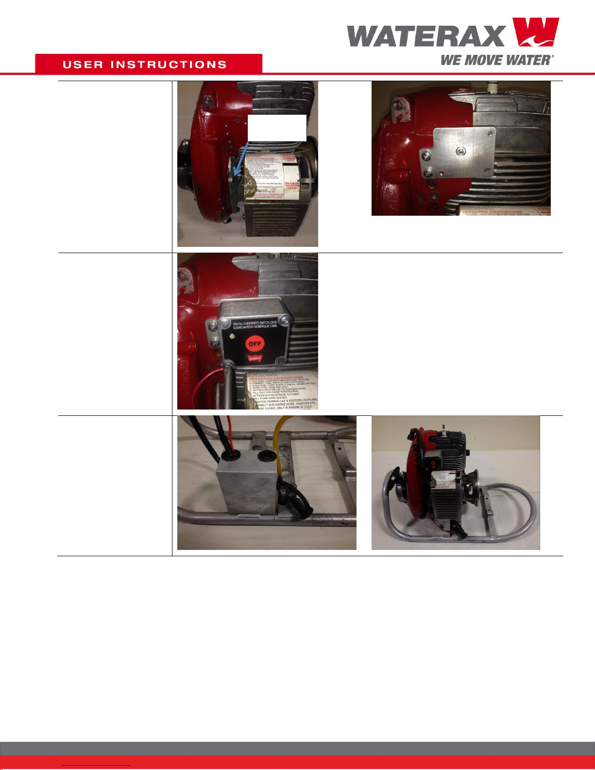
Starting the engine:
Before starting the engine, slowly pull the starter rope and crank over the engine a couple of times in order to charge up the
DOS. The LED will light up and flash to indicate that the DOS has been charged and that the MARK-3®is ready to be
started.
Start the engine as directed in the MARK-3®Instruction & Service manual. (Note that there is no “ON” switch).
Stopping the engine:
To stop the engine, press and hold the OFF button until the engine shuts down.
Overspeed condition:
If the engine overspeeds (e.g., during a loss of prime), the DOS will immediately shut down the engine.
Always ensure that the cause of the overspeed condition has been identified and corrected before attempting to restart the
engine.
When attempting to restart the engine (after an overspeed condition or after pressing the OFF button), wait 10 seconds from
the time the engine shut down. This will enable the DOS to reset itself. Failure to wait the prescribe duration of time will
make it difficult to start the engine. It may lead to a flooding condition.
Warranty, Service and Support:
Product and service documentation such as tech notes, data sheets, manuals and information on the limited warranty
provided on products manufactured by WATERAX can be found on our Web site at: www.waterax.com.
WATERAX Inc.
6635 Henri-Bourassa Blvd. W.
Montreal, QC, H4R 1E1
Tel.: (855) 616-1818
(514) 637-1818
Fax: (514) 637-3985
Copyright © 2018 WATERAX Inc. Publication Number: 701161, Rev.8 All rights reserved. Printed in Canada.
Other manuals for MARK-3
4
Table of contents
Popular Lawn And Garden Equipment manuals by other brands

Coopers of Stortford
Coopers of Stortford 11434 Instructions for use

Billy Goat
Billy Goat Grazor GZ400H Operator's manual

Agri-Fab
Agri-Fab VAC-N-GO 45-0407-131 owner's manual

DECKORATORS
DECKORATORS ALX CLASSIC Tech Guide

Kress Robotik
Kress Robotik MISSION KR120E owner's manual

Simplicity
Simplicity 990206 Instructions and parts list

Husqvarna
Husqvarna 335LX-SERIES 335LS Operator's manual

Ryobi
Ryobi RY28005 Operator's manual

Montgomery Ward
Montgomery Ward ZYJ-256A Owner's guide and parts list

CASARIA
CASARIA DBGB001 instructions

P3 International
P3 International P7810 PIR Animal-Away instruction manual

New England Arbors
New England Arbors The Raised Planter Trellis Assembly instructions