Waterco Top Discharge User manual
www.waterco.com
WARNING
!
WATERCO POOL HEAT PUMP
User and
Care Guide Manual
This equipment must be installed and serviced by a qualified technician.
Improper installation can create electrical hazards which could result in property
damage, serious injury or death. Improper installation will void the warranty.
Notice to Installer
This manual contains important information about the installation, operation and
safe use of this product. Once the product has been installed this manual must
be given to the owner/operator of this equipment.

Table of
A NOTE TO YOU ---------------------------------- 02
GENERAL SAFETY ------------------------------- 03
INSTRUCTIONS
INSTALLATION INSTRUCTIONS ---------------- 05
Location --------------------------------------- 05
Water Piping ---------------------------------- 07
Plumbing Diagram --------------------------- 07
Electrical -------------------------------------- 08
Electrical Connection ------------------------ 08
Bonding --------------------------------------- 09
Bonding Diagram ----------------------------- 09
OPERATION OF YOUR POOL HEAT PUMP ---- 10
Initial Heating ---------------------------------- 10
Pool Heat Pump Running Time -------------- 10
Pool Solar Blanket ---------------------------- 11
Defrost Cycle ---------------------------------- 11
Electronic Control with Diagnostics ------ 11
and Reversible (XLR) Electronic
Control with Diagnostics
To Start The Pool Heat Pump ---------------- 12
To Stop The Pool Heat Pump ---------------- 12
To Check and Adjust Temperature Settings - 12
Specic Functioning of Your Reversible ----- 13
Electronic Control with Diagnostics
Temperature Calibration ---------------------- 14
Operation of Multi Function Electronic --- 15
Control Panel
To Start the Pool Heat Pump ---------------- 15
To Stop the Pool Heat Pump ---------------- 15
To Raise or Lower Desired Water ------------ 16
Temperature
To Change Display from Farenheit ---------- 16
to Celcius
Defrost for Electroheat Subzero ------------- 16
Electrical connection of an automatic ------ 17
mode for the pool and spa (Smart Energy
model only)
How to Program The Multi Function -------- 18
Electronic Control Timer to Control Your
Pool Pump Filtration
How to Program The Timer ------------------ 18
How to Stop The Timer ---------------------- 18
Electrical connection required to use ------- 18
the integrated pool water pump timer
of your pool heat pump
Protection Devices ---------------------------- 20
Adjustment of The Bypass Valves ----------- 20
MAINTENANCE OF YOUR POOL HEAT PUMP- 21
Winterizing ------------------------------------------ 21
TROUBLESHOOTING ----------------------------- 22
Nothing Is Working and The ----------------- 22
Electronic Control Does Not Operate
Nothing Is Working But The Electronic ------ 23
Control Temperature Displays Digits
or a Code
Fan Doesn’t Work (The Fan Blades ---------- 23
Are Not Moving)
Fan Blades Turn, But Compressor ----------- 23
Is Not Functioning
Compressor Starts and Stops --------------- 24
There Is Water Around The Pool Heat Pump-24
Pool Heat Pump Has Ice Formed ------------ 25
On The Evaporator Coil
Pool Heat Pump Is Functioning, But Does -- 26
Not Reach The Desired Temperature Setting
Analysis Chart --------------------------------- 27
Circuit Breaker Trips -------------------------- 27
The Pool Heat Pump Is Noisy ---------------- 28
The Temperature Shown On Pool Heat ----- 28
Pump Is Not The Same That Is
Shown By The Pool Thermometer
Service Analyser Codes --------------------- 29
WARRANTY ---------------------------------------- 33

A NOTE TO YOU
Congratulations!
You have made an excellent choice! The Waterco pool heat pump will give you unique
comfort at low-price.
Using the latest technology in heat capture, the Waterco pool heat pump converts the
energy released by the sun and transfers it efciently to your swimming pool.
During certain periods it may be necessary to operate your pool heat pump continuously
however this should not be of concern as your Waterco pool heat pump can heat up
your pool 80% more economically than the fossil fuel heating or heaters with electric
elements.Waterco pool heat pumps are designed specically to heat up your swimming
pool economically.
To appreciate the benets that the product will bring you, make sure to operate the unit
when the atmospheric conditions specied in this document are present in addition of
using a solar blanket to minimize heat loss. Pools not covered with a solar blanket lose 2 to
3 times more heat, regardless of types of heating!
I pg 02
Pool Heat Pump

Record your model’s information.
Keep this manual and your original proof of purchase receipt for warranty and future
reference.
On the base of your pool heat pump is a name plate which contains information such as
model number, serial number and electrical information.
Please write these down below and have them handy incase of a service call request.
Model Number _______________________________________________________________
Serial Number _______________________________________________________________
Purchase Date _______________________________________________________________
Dealer Name _______________________________________________________________
Dealer Address _______________________________________________________________
Dealer Phone _______________________________________________________________
We have provided important safety messages in this manual and on your pool
heat pump. Always read and obey all safety messages.
This is the safety alert symbol.
This symbol alerts you to hazards that can kill or hurt you and others.
This is a very important label.
This symbol alerts you of instructions that MUST be followed properly in order to
ensure that your warranty will not be voided.
These are instructions that must be respected in order to protect the user’s health
and to ensure that your warranty will not be voided.
IMPORTANT
!
VITAL
WARNING
!
GENERAL SAFETY INSTRUCTIONS
To nd detailed product information, the location of the nearest dealer or to register your
pool heat pump please visit our website www.waterco.com and select your location.
All electrical connections must be carried out by a qualied electrician, according to the
local electrical codes. Always cut off the unit’s main power whenever the access panel is
open or removed. It is strongly recommended that the pool heat pump is installed outdoors
(unless approved by the manufacturer), while respecting the minimal clearances needed for
proper operation and heating. Please refer to “Location” on the following page
MAKE SURE THE INSTALLATION WAS CARRIED OUT ACCORDING TO THE
INSTRUCTIONS OF THIS MANUAL. SEE “INSTALLATION” SECTION.
MAKE SURE YOUR POOL HEAT PUMP WAS PROPERLY GROUNDED AND BONDED.
SEE “BONDING” AND “BONDING DIAGRAM” SECTIONS.
BEFORE ASKING FOR ASSISTANCE OR SERVICE, PLEASE READ CAREFULLY THE
SECTIONS ON “TROUBLESHOOTING ” AND “WARRANTY”.
!
VITAL
I pg 04
Pool Heat Pump
Proper pool chemistry is vital to the longevity of your pool heat pump. Pay particular
attention to the total alkalinity and total dissolved solids. It is highly recommended that
you have your pool chemistry checked often by an outside independent pool store. Your
pool water chemistry must be maintained at all times as shown in the table below to prevent
damage to your pool heat pump.
WARNING
!
IMPORTANT
DESCRIPTION NORMAL RANGE* VERIFY
PH Level
Chlorine Concentration
Total Alkalinity
Total Dissolved Solids
Calcium Hardness
7.4 to 7.8
1.0 to 4.0 PPM
100 to 120 PPM
below 1800 PPM Reg. Pool
below 3500 PPM Salt. Pool
200 to 300 PPM
1 per week
1 per 2-3 days
1 per 2-3 weeks
1 per month
1 per month
1 per month
* Warranty can be voided if not maintained within these ranges.
USAGE OF CHEMICAL PRODUCTS
Never add liquid chlorine, granular chlorine, or slow dissolving tablets/ pucks into the
skimmer basket. This high concentration of chemicals should be avoided.
Water quality standards that must be strictly adhered to*:
GENERAL SAFETY INSTRUCTIONS
GENERAL SAFETY INSTRUCTIONS
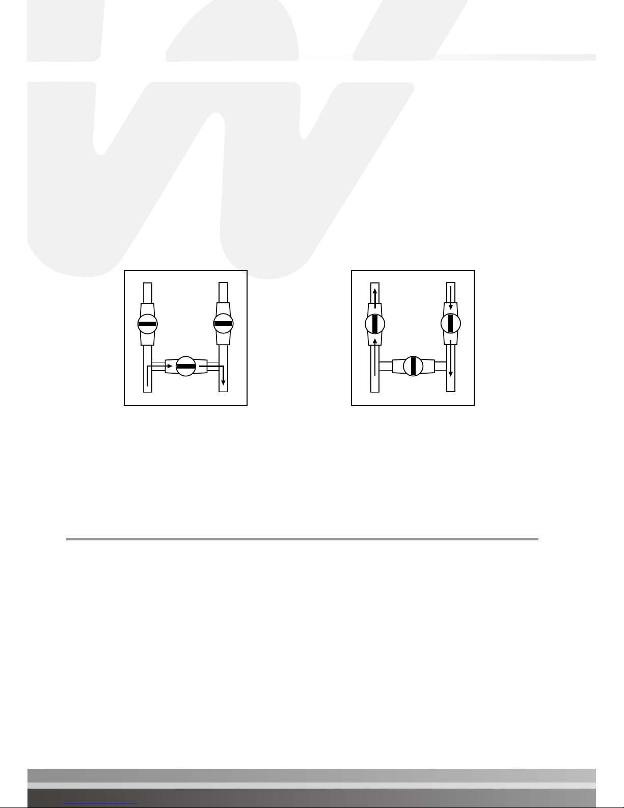
DO NOT DEPRIVE YOUR POOL HEAT PUMP OF WATER FLOW FOR MORE THAN
24 HOURS WITHOUT DRAINING IT. Make sure you leave the bypass valves as
shown in Figure 1.
At the end of each season, when the pool heat pump is no longer in use, and proper
pool water chemistry is not maintained, it should be disconnected from the water line and
drained to prevent any possible corrosion or damage to the pool heat pump. Refer to Figure
1 below or interizing procedure (page 21).
INSTALLATION INSTRUCTIONS
Location
In order to gain maximum efciency please follow the instructions when deciding where to
position your pool heat pump. It is also important to allow clearances for future service and
maintenance procedures.
The unit is designed for outdoor installation and should not be installed in a totally enclosed
area such as a shed, garage, etc., unless ventilation is provided to ensure adequate
air exchange for proper operation. Re-circulation of cold discharged air back into the
evaporator coil will greatly reduce unit’s heating capacity and efciency.
Pool heat pump Pool heat pump
OUT
IN
OUT
IN
When your valves position are as
shown on Figure 1, the water is
bypassing the pool heat pump.
Figure 1
When your valves position are as
shown on Figure 2, the water is going
through the pool heat pump.
Figure 2
The valves shown above may be different to the ones installed on your system.
Please ensure you understand how your bypass valve operates.

I pg 06
Pool Heat Pump
INSTALLATION INSTRUCTIONS
Location
The unit should be located as close as practically possible to the existing pool pump and
lter to minimize water piping. The use of 90 degree bends and short radius elbows in the
water piping should be kept to a minimum.
Mount the unit on a sturdy base, preferably a concrete slab or blocks. The base should be
completely isolated from the building foundation or wall to prevent the possibility of sound
or vibration transmission into the building. The size of the base should not be less than the
base of the pool heat pump.
Your pool heat pump will accumulate condensed water (approx. 1 to 1.5 gallon or 4
to 6 litres per hour), therefore causing water to drain out of the unit base. In order to
avoid water accumulation, you may use decorative rocks around the concrete slab or
a basin under the unit. (Please note this is a normal characteristic of a pool heat pump and
not a service or warranty issue.)
Air is pulled through the evaporator coil and discharged through the top or front grill.
Clearances should be allowed in front and around the unit for unrestricted air
discharge and service access. See Figure 1 and Figure 2.
Re-circulation of cold discharged air back into the evaporator coil will greatly reduce
unit’s heating capacity and efficiency.
IMPORTANT
No obstruction above
24” to 36”
(60 to 91 cm) min.
24” to 36”
(60 to 91 cm) min.
24” (60 cm) min.
24” to 36”
(60 to 91 cm) min.
24” to 36” (60 to 91 cm) min.
5’ (1.5m) min.
18” (46 cm) min.
18” (46 cm) min.
24” (60 cm) min.
Top Discharge Models Side Discharge Models
Figure 1 Figure 2

INSTALLATION INSTRUCTIONS
Water Piping
The following piping sequence must be followed without exception: 1-pool pump 2-lter
3-pool heat pump 4 chlorinator (when installed). Rigid PVC piping is recommended, all
joints should be glued with PVC glue. If rigid PVC is not available, you can use soft or
exible piping with stainless steel clamps. When the piping installation is complete, operate
the pool pump and check the system for leaks. Then check the lter pressure gauge to see
that excessive pump head pressure is not indicated. NOTE: Units are designed to operate
with a minimum water circulation of 132 LPM/35 GPM.
NOTE: A bypass kit is strongly recommended and should be installed for adjustment of
water flow and ease of service.
1. Either a 1/3 pound check valve or a loop MUST be installed between the pool heat
pump and any automatic chlorinator to prevent highly chlorine concentrated water from
owing back to the pool heat pump when the pool pump is not running.
2. Units which are located below the water level of the swimming pool may require the
pressure switch to be adjusted.
This can be checked by the following method:
i) switch on the water pump and pool heat pump.
ii) while the pool heat pump is running switch “OFF” the water pump.
If the pool heat pump shuts down automatically no further action is required.
If the heat pump continues to run you will need to have a qualied technician adjust the
water pressure switch. For further information please, contact Waterco.
!
VITAL
Plumbing connections to
the heater must be made by
hand only as it may break
the water Inlet or Outlet
connections.
IMPORTANT
Plumbing Diagram
Hookup

I pg 08
Pool Heat Pump
IMPORTANT
Electrical
To ensure your safety and ensure the adequate functioning of your pool heat pump, all
electrical work should be performed by a fully qualified and licensed electrician in
accordance with local electrical codes.
An adequate circuit breaker and copper wiring must be used. This information is available
on the name plate of the pool heat pump. It may be necessary to install a ground circuit
breaker.
THE POOL HEAT PUMP MUST BE DISCONNECTED BEFORE
OPENING THE ACCESS PANEL.
WARNING
!
Electrical Connection
Standard 60 Hz power supply : 208/240 v - 60Hz-1 phase
Standard 50 Hz power supply : 208/240 v - 50Hz-1 phase
3 phase power supply : 200/230 v - 50/60 Hz - 3 phase
380/420 v - 50/60 Hz - 3 phase
Breaker Size
Please consult name plate on the base or the side of your pool heat pump for running
amperage and required breaker size.
Electrical Wire Size
Please consult a qualied and licensed electrician.
WARNING
!
The power cable ground must be connected to the electrical panel and to the ground
lug of the pool heat pump. An improper installation may be a potential cause of fire,
electrical shock or injury.
INSTALLATION INSTRUCTIONS

Because all metals have different electrical potentials, ALL metal and electrical
components of the pool system MUST be bonded together. This includes the metal
framework of the pool, the light, the pump, the lter (if metal), the pool heat pump, any
automatic chlorine generator, and any other metal or electrical equipment bonded to your
pool.
On some older pools, this substructure bond wire may not exist. In these cases, a 3 - 4
foot solid copper rod must be driven into the ground near equipment; all electric and metal
components must be bonded to each other, and to the copper rod. Warranty will be voided
if system is not properly bonded.
CAUTION: It is recommended when using automatic chlorinators , to ensure that they
are properly installed and bonded. Some of these systems may leak stray voltage and
currents into the water causing severe electrolysis. This dramatically shortens the life
of the pool heat pump and will void the warranty.
NOTE: Bonding to pool pump is not required to above ground pool pumps but all
other equipment must be bonded.
!
VITAL
Bonding
!
VITAL
Bonding Diagram
Pool House
Breaker Box
Power Supply
and Grounding
Wires Conduits
Chlorine
Generator
Heat Pump
Need bounding
if it is a metal lter
Pool Pump
If Pool Bonding Wire does
not exist, then a 3’ to
4’ Copper Rod must be
driven into the ground and
equipment bonded to it.
Light
3’ to 4’ Copper Rod
Bonding Wires
Pool Bonding Wire
INSTALLATION INSTRUCTIONS
I pg 10Pool Heat Pump
OPERATION OF YOUR POOL HEAT PUMP
Initial Heating
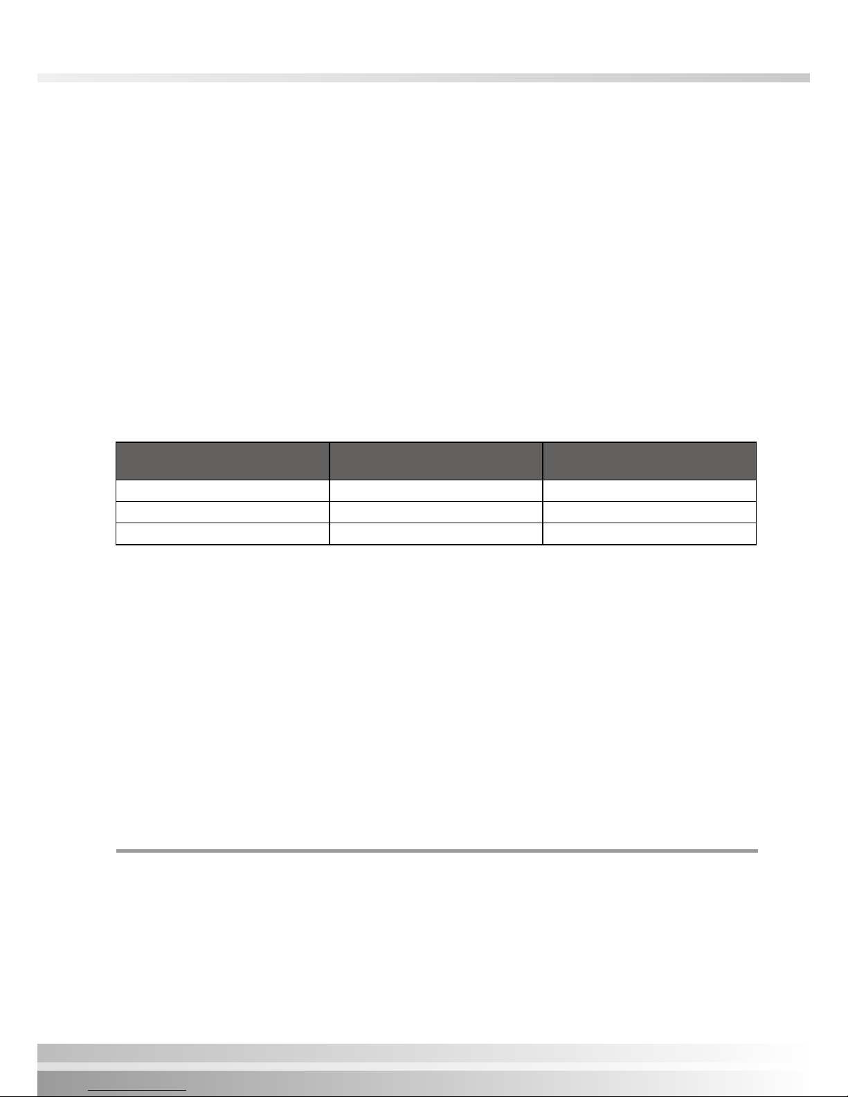
Atmospheric conditions as well as the pool water temperature should not be below the
minimum operating temperatures as stated below in order to obtain efciency and avoid
codes from appearing on the electronic control temperature display; these codes are not
generally a problem with the pool heat pump at these conditions and is not covered by the
warranty.
If temperatures are below the minimum temperatures listed the pool heat pump should not
be operated and must be switched off.
For Electroheat SubZero and Reversible (XLR) units, they will automatically stop without
human intervention.
Model Atmospheric conditions
must be above
Pool water temperature
must be above
Electroheat SubZero 32°F (0°C) 50°F (10°C)
Reversible (XLR) 43°F (6°C) 65°F (18°C)
All others 52°F (11°C) 65°F (18°C)
The speed of heating is dependent upon ve basic factors:
1. Size of the pool.
2. How many degrees the water is to be heated.
3. Ambient air temperature - the warmer the air, the less time required to heat.
4. Use of a solar blanket .
5. The size of the pool heat pump.
To achieve initial heating, your pool heat pump and the pool pump may work up to 24 hours
per day until desired temperature is achieved. The initial heating time may vary depending
upon the above ve factors. After initial heating, operating time may be reduced to match
daily heat loss.
Pool Heat Pump Running Time
Most units should be sized to operate during the pool ltering cycle time of 8-12 hours
daily, providing an even, steady ow of warm water. On warmer days the pool heat pump
will run less because the heat loss will be less. Pool heat pumps are able to operate 24
hours per day when necessary.

Electronic control with diagnostics and Reversible
(XLR) electronic control with diagnostics
Pool Solar Blanket
A pool solar blanket should be used whenever possible. Blankets minimize heat loss and
conserve heat in your pool. Un-blanketed pool lose 2-3 times more heat than a blanketed
pool
Defrost Cycle
When any of the following conditions occur the electronic control of your unit will activate
a defrost mode until all frost from the evaporator has melted. Condensation of water on the
evaporator coil tends to frost up quicker when the following occur.
1. When atomospheric conditions are as stated above;
2. When the evaporator is dirty;
3. When installation clearances are not respected.
Defrost is activated for between 3 to 20 minutes.
Electronic Control
with diagnostics
Reversible (XLR) electronic control
with diagnostics

I pg 12
Pool Heat Pump
To Start The Pool Heat Pump
Press the button on the electronic control ON/OFF to start the pool heat pump. The
temperature display will show the pool water temperature owing in your pool heat pump
and the fan motor starts (fan blade turns) but the compressor does not start.
The temperature display ashes until the compressor starts and when the timer will complete
its cycle of 3 to 5 minutes. After 5 minutes, the compressor starts and the temperature on
the display stops ashing.
You can now program the desired temperature for the pool water.
To Stop The Pool Heat Pump
The pool heat pump can be stopped by pressing the ON/OFF button once.
To Check and Adjust Temperature Settings
To program the desired water temperature, press BOTH the UP and DOWN arrow keys at
the same time until the temperature degree displays change degree, then release them.
Press the UP arrow or DOWN arrow to program the desired temperature. The temperature
setting will automatically ash and will be saved. The display temperature will be revert
back to the pool water temperature when all keys have remained untouched for 5 seconds.
To change the temperature display from Fahrneheit (˚F) to Celcius (˚C). Press, the button
˚C/˚F. The led below the ˚F or ˚C will be lit to indicate the current selection.
Note: The pool heat pump will cut out at once when the programmed temperature has
been reached.

Electronic Control
with diagnostics
Reversible (XLR) electronic control
with diagnostics
In addition to controlling the temperature of the water, this electronic control informs you
on the operation of your pool heat pump or any faults that may arise by displaying codes
on the temperature display.
When the unit is in defrost mode the code “DEF” is dispalyed on the temperature display.
This under normal conditions is not considered to be a fault.
Specific functioning of your reversible electronic
control with diagnostics
During the defrost cycle, the fan motor stops working and the hot gas is injected into the
evaporator to melt the frost. However, when the unit makes 4 cycles (heating and defrost)
consecutive within 1-hour, the unit goes into protection mode to avoid inefcient use of
electricity. These frequent defrost cycle’s mean that the conditions of ambient temperature
and humidity do not allow to heat your pool water. The DEF code and the water temperature
will be displayed alternately on the electronic control. Refer to the section titled ¨ Service
Analyser Codes ¨ to validate what you should do.
Codes
If a code appears on the electronic control refer to Service Analyser codes (all models) on
page 29.

I pg 14
Pool Heat Pump
Temperature Calibration
It is possible to have a temperature variation between the water in the swimming pool and
the reading of the pool heat pump temperature probe (sensor). Example:if the water in the
pool is 26º C (80º F) and the heat pump electronic control displays 24ºC (76º F).
To calibrate this variation, perform the following procedure:
1. With the use of an accurate thermometer read the pool water temperature (e.g: 26˚C).
2. Read the temperature displayed on the pool heat pump electronic control (eg: 24˚C).
3. To determine the differential subtract the pool water temperature from the pool heat
pump displayed temperature, 26 - 24 = 2˚C. Therefore we must compensate for the 2˚C
variation.
4. Press BOTH the UP and DOWN arrow keys until the programmed temperature is
displayed ( the temperature you have previously set) then release both buttons.
5. Press the ON/OFF button and release.
6. Using the UP and DOWN arrows, enter the calibration value, (2˚C). In this case, by
pressing the UP arrow twice.
7. After 5 seconds when all the buttons have remained untouched , the display temperature
will show the pool water temperature as per your thermometer. If this is the case the
calibration process was successful.
Operation of Multi Function Electronic
Control Panel
The temperature display of the electronic control panel is factory set to show pool water
temperature in degrees FAHRENHEIT. See “To select temperature in ˚C or ˚F” section on
the following page.
To Start The Pool Heat Pump
When the pool heat pump is turned “ON” or after a power shut down, the panel lights up
and either indicates “OFF” or the temperature of the pool water circulating inside the pool
heat pump.
When the unit is rst turned on and water is owing, the fan motor will start (blades will
turn) followed by the compressor 3 to 5 minutes later. ( the compressor and fan may start
together when the unit has automatically cycled off for a period of time and then restarts)
To Stop The Pool Heat Pump
The pool heat pump can be stopped by switching off the electrical power supply or by
setting the desired water temperature setting to below 60˚F (15˚C).
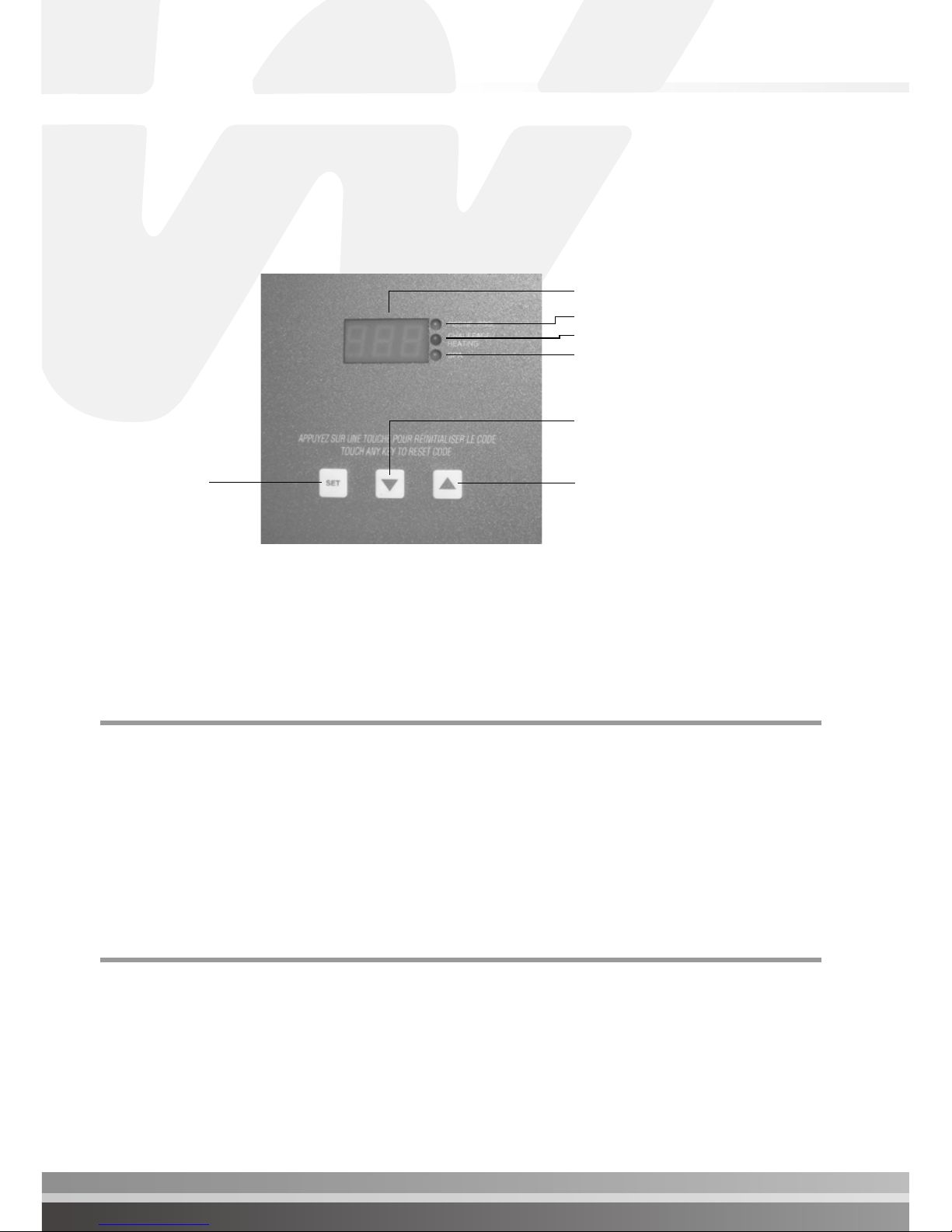
Actual temperature and setting display
Pool Mode
Compressor running
Spa Mode
To toggle
between
functions
To lower desired temperature or
to change settings
To raise desired temperature or
to change settings

To Raise or Lower Desired Water Temperature
(Pool or Spa Mode)
The Multi function electronic control has the capability of memorizing two different
programmed temperature settings as follows:
For POOL the maximum is 95°F (35°C) and for SPA the maximum is 104°F (40°C)
To access the pool (POL) mode or spa (SPA) mode, press the SET key until you see P-S
and then press the UP or DOWN key to switch to POL or SPA.
Push the SET key again to enter into the desired heating temperature mode.
Press the UP or DOWN arrow to increase or decrease the temperature setting by one degree
at a time. Once the heating mode is programmed, it will be displayed for approximately 5
seconds; then the temperature display will return to the actual pool water temperature. The
light on the right side of the display indicates the chosen heating mode .
To change display from Farenheit to Celcius
1. Press and release the SET key until F-C appears on the temperature display.
2. Whilst F-C is still on the display Press and release the UP or DOWN arrow key until C
is displayed.
3. Release all keys and the control will now be set for Celcius. (do not press any other keys
for 5 seconds)
To go back to Farenheit follow the same instructions above, however when you are at step
2, F will need to be shown on the display before releasing all keys
Defrost for Electroheat SubZero
During the defrost cycle, the fan motor stops working and the hot gas is injected into the
evaporator to melt the frost. However, when the pool heat pump makes 5 consecutive
cycles (heating and defrost) in less than 15 minutes, the unit goes into protection mode to
avoid inefcient use of electricity. These frequent defrost cycle’s mean that the conditions
of ambient temperature and humidity do not allow to heat your pool water. The FS4 code
will be displayed on the electronic control. Refer to the section titled ¨ Service Analyser
Codes ¨ to validate what you should do.
I pg 16
Pool Heat Pump

Electrical connection of an automatic mode for the
pool and spa (for Smart Energy model only)
The Multi Function electronic control has the ability to switch from POOL to SPA mode
automatically .This function is used when warm water is directed towards the SPA.
Activation is carried out by using an external water pressure switch connected to the SPA
water line. This connection must be done by a qualied technician.
When the electronic control of the pool
heat pump is located inside the electrical
box the 2 wires coming from the pressure switch
connected on the water piping going to the SPA
(as shown on the right) must be connected at the
boundaries of the electronic control of the pool
heat pump.
When the electronic control of the pool
heat pump is mounted on the front panel
of the unit: The Orange and Orange-Black wires located inside the electric box junction
of the pool heat pump must be connected to the water pressure switch connected on the
water piping going to the SPA.
Electrical connection to an automation system to the pool (for Smart
Energy model only) It is possible to carry out the connection of the Multi Function
electronic control to an automation system for models P4 or P8. This type of connection
must be done by a qualified technician to ensure that your warranty will not be voided.
For automation system operation, you will need to set the SPA temperature to maximum
40˚C (104°F) and the POOL setting to ‘‘OFF’’, so that when the automation system calls for
heat; it will activate the SPA mode and starts the pool heat pump.
Note: When calling for a service technician, you will have to mention the installation of this
type of automation system.
Pool/Spa
WS DS AS P/S
HP LP
SPR2
FLOCOMP
AC F1 F2 F3
PUM P12120
~~
Codes
For codes refer to the section titled “Service Analyser codes”.

I pg 18
Pool Heat Pump
How to program the Multi Function electronic
control timer to control your pool pump filtration
Note: This option is available only on the Smart Energy pool heat pump model.
The Multi Function electronic control includes an adjustable internal timer, which allows to
control the ltration time of the pool pump. This timer allows 6 cycles of filtration during
a day.
Example:
Desired time of ltration: 3 hours / day = 180 minutes / day
Calculation: 180 minutes/day DIVIDED by 6 cycles of ltration/day = 30
Finally, your pool pump will work 6 times a day during 30 minutes; however, if the water
temperature programmed has not reached, the pool pump will work until it reaches the
programmed water temperature.
How to program the timer
1. Press the SET key until FIL is displayed;
2. If you want the pool pump to work continuously; press the up or down arrow until ON
is displayed;
3. If you want the pool pump to work during a specic period, press the up or down
arrow until the number of hours per day of the ltration that you desire is displayed (for
example: you would like 3 hours/day, the number 3 must appear on the Multi Function
electronic control).
Note: This type of programming FAVOURS the maintaining of the programmed water
temperature rather than the time of ltration.
How to stop the timer
1. Press the SET key until the Multi Function electronic control displays FIL;
If you do not want to use the timer included in the Multi Function control, press the up or
down arrow until OFF is displayed.

Electrical connection required to use the integrated
pool water pump timer of your pool heat pump.
Note: This option is available only for Smart Energy model.
If you wish to use the integrated timer of your pool heat pump; you must warn your
electrician at the time of installation. All electrical work should be performed by a fully
qualified and licensed electrician in accordance with local electrical codes. The pool
pump MUST not consume more than 16 amps.
NOTE: The junction box of the timer does not provide power for the swimming pool pump,
but instead switches the power (which is fed from another source) on and off to control
the pump. An adequate circuit breaker dedicated to the swimming pool pump must be
installed with copper wiring used in order for the bencial functions of the timer. It may be
neccessary to install a ground fault circuit breaker.
IMPORTANT
Use the junction box at the base of pool heat pump
For model Smart Energy System Only
Wiring colour codes are:
Green : Ground
Black : Input L1
White : Input L2
Orange : Output T1
Red : Output T2
JunctionBox
for the timerPool Pump Beaker
Pool Pump
This manual suits for next models
1
Table of contents
Other Waterco Swimming Pool Pump manuals


Popular Swimming Pool Pump manuals by other brands

Pentair
Pentair STA-RITE SWIMMEY Series instruction manual

Sunlover
Sunlover Oasis Inverter Series Installation instructions manual

Evolution
Evolution Evoflow Storm Eco-V Installation and operation manual

PoolRite
PoolRite Enduro EP 750 user manual

Intex
Intex 633 owner's manual

Intex
Intex Krystal Clear SX2800 owner's manual


