WaterDog Adventure Gear WAG Boarding Steps SLM-12 User manual

WaterDog Adventure Gear®
WAG Boarding Steps™
Model SLM-12
Owner's Manual
Read this manual completely and follow instructions prior to use.
Improper use may cause injury and/or equipment damage.
WAG Boarding Steps have a maximum capacity of 130 pounds and are designed for dog use only.
U.S. Patent No. 8,596,212

2
Welcome to the WaterDog Adventure Gear® family and thank you for your purchase!
As excited as you and your dog are to begin using your WAG Boarding Steps, there are a few important actions to take
prior to use and for safe and enjoyable ongoing ownership.
Assembly Overview
1/2" Detent Ring Pin
1/2" Pivot Pin
Torsion Spring
Runner
Step
Retention Cord
Lower Mounting Assembly
Upper Mounting Assembly
Lower Mounting Arm
Sleeve
Brace Arm
Arm Attachment
1/4" Detent Ring Pin
Upper Mounting Assembly
Lower Mounting Assembly
Pivot Bar
Lower Mounting Arm
Spacer

3
Initial Setup Prior to Use (Fitment)
Tools Required: 7/16" socket driver, 5/32" hex driver
Your new WAG Boarding Steps come assembled from the factory. For safe and optimum performance, the initial setup
(fitment) for your specific boat must be performed prior to use since boat swim ladders come in many different styles,
shapes and sizes. The initial setup is best done with the boat out of the water to observe fit.
WAG Boarding Steps are designed to work on the majority of boat swim ladder designs. The step assembly should be
fitted for:
•the hook size to minimize fore and aft movement of the steps
•the angle and rung positioning of the boat swim ladder to achieve the proper angle of the steps when installed
•the width of the boat swim ladder to minimize relative lateral movement of the steps
WAG Boarding Steps are designed to mount on swim ladder designs that have:
•a lower horizontal cross-member (pivot bar or rung) that is at least 18" below the upper cross-member
•a cross-member cross-section of no more than 1-1/2" in two 1"-wide areas; if more than 1-1/2", an optional
adjustable hook kit may be required
Most 3-step (or more) folding and telescoping swim ladders meet these criteria. A 2-step swim ladder with pivot bar will
also typically meet these criteria.
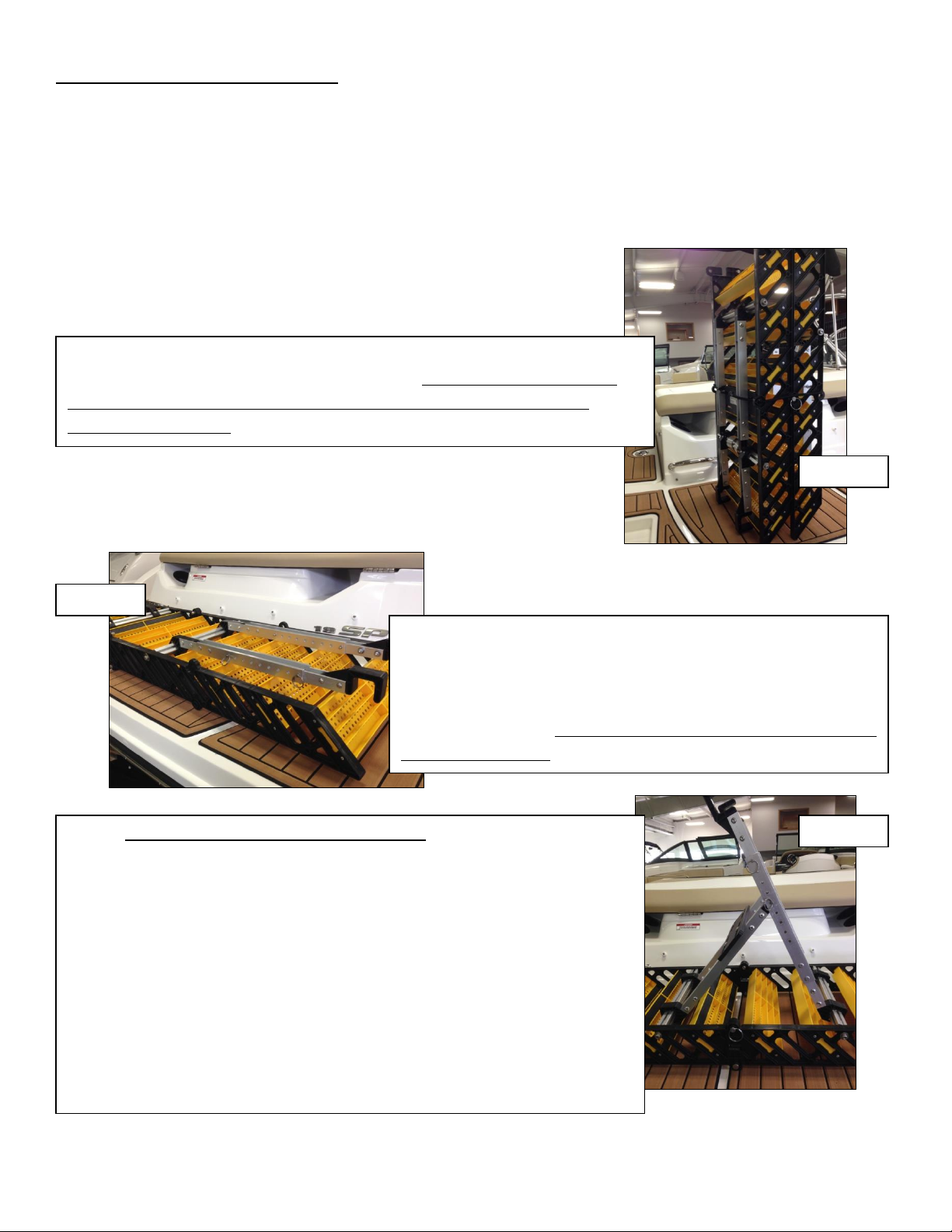
Hook Size
Carefully remove the folded assembly from the package. Stand the unit up on a flat surface with the mounting arms
pointing up. The retention cord should be fastened around the assembly to prevent the mounting arms from pivoting
open or bending. The end of the arms will have exposed metal edges until the hooks are installed. The steps were
supplied with two hook opening sizes, 1" and 1-1/2". Select the size that fits best over the cross-members of the boat
swim ladder by trying them as loose pieces. Install the hooks on the upper and lower mounting arms using the
hardware supplied in the arm attachment holes. The hooks will only install one way. The screw head should be on the
outboard side of the arms and the washer and lock nut should be on the inside of the arms. The stainless steel
hardware is pre-treated with ECK® Corrosion Protection Compound which also serves as an anti-seizing agent. Tighten
firmly. If neither of the hook sizes fit, it may be necessary to obtain the optional adjustable hook kit accessory.

4
Angle and Rung Positioning
Boat swim ladders have different angles and rung dimensions. The mounting arms are preassembled to provide
adequate adjustment for the majority of boat swim ladder designs. To determine the mounting arm positioning to
achieve the proper angle of the steps when installed:
Figure 1
Figure 2
Figure 3
Step 2 - Remove the two (2) 1/2" detent ring pins, carefully unfold
the steps by spreading the ends until the assembly is laying flat, and
insert the pins through the 1/2" holes adjacent to the 1/2" pivot
pins. (Figure 2) Tip: Keep pin rings around fingers while handling to
avoid losing the pins. Caution: Do not twist or torque the assembly
during Steps 2 and 3.
Step 3 - This step will likely take several iterations. The amount the lower
mounting arms extend out of the lower mounting arm sleeves and the angle
formed by the brace arm connection will vary depending upon the boat's swim
ladder angle. Remove the four (4) 1/4" detent ring pins from the lower
mounting arm sleeves. Slide the lower mounting arm out of the sleeve (if
necessary), swing the brace arms to line up connector holes in with one of the
middle adjustment holes in the lower mounting arms, and reinsert the pins
through the 1/4" holes in both arms. When finished, there should be two (2)
pins where the brace arms connect and the other two (2) pins should be
positioned through the holes in the mounting arm sleeve closest to the hook.
(Figure 3) Tip: Keep pin rings around fingers while handling to avoid losing the
pins.
Step 1 - Stand the folded assembly on end with the hooks down, unhook the
retention cord and let hang to the side. (Figure 1) Caution: Maintain a secure
grip on the stretched retention cord when unhooking and slowly relax the
tension to avoid injury.

5
While unlikely, if the appropriate assembly angle cannot be achieved as outlined above, it may be necessary to
reposition the lower mounting arms and/or braces. If repositioning the arms, place the assembly on a horizontal surface
with the arms pointing upward. Remove the 5/16" shoulder bolts on both sides using a 5/32" hex driver. Move the
lower mounting arm assembly and/or brace assembly to a different set of mounting holes in the runners and repeat
Steps 3, 4 and 5.
Figure 4
Figure 5
Step 4 - Lift the assembly into place by positioning the lower mounting arm
hooks on a lower cross-member of the boat swim ladder (typically the second
or third rung from the top), retract the spring-loaded upper mounting arms,
pivot the steps toward the boat swim ladder to position the upper mounting
arm hooks under the upper cross-member of the boat swim ladder (typically
the top rung or pivot bar), and engage the upper mounting arm hooks on the
upper cross-member by slowly and carefully releasing the upper mounting
arms. (Figure 4) Caution: Be careful not to place any body parts in the path
of the spring-loaded upper mounting arms.Note: If the hooks are positioned
wider than the cross-member width, perform the width adjustment (Page 6)
first.
Step 5 - If the steps are not approximately level (assembly at
about a 45 degree angle), remove the assembly by reversing
Step 4, reposition the brace arms and lower mounting arms in
a different set of adjustment holes in the lower mounting arm
sleeves, and remount the assembly. (Figure 5) Repeat until
the assembly steps are approximately level. The adjustment
flexibility also allows for some positioning of the top step.
Once the correct adjustment holes have been identified for the
pins, mark the holes for quick set-up next time.

6
Width
Boat swim ladders have different widths. The hooks/mounting arms are preset from the factory to a width of 8-1/2",
but are adjustable for width to maximize stability and minimize relative movement. To determine and adjust the width:
Figure 6
Figure 7
115
Step 1 - With the step assembly mounted on the ladder, measure the gap,
if any, between the hooks and the boat swim ladder side frames on both
sides of each mounting cross-member. It is highly recommended that at
least one set of hooks (upper or lower) be positioned against the swim
ladder side frames to ensure stability. (Figure 6)
Step 2 - Remove the assembly from the boat swim ladder and place
the assembly on a horizontal surface with the arms pointing
upward. Loosen the arm attachment and spacer nuts using a 7/16"
socket driver. Splitting the difference in total gap from the
measurements taken in Step 1, slide the mounting arms outward
equally and retighten the nuts. The gap between the arms and
runners on both sides should be equal. (Figure 7)

7
Congratulations! You have completed the initial setup of WAG Boarding Steps for your boat and are now ready for
hours of enjoyment without ever needing to use tools again. To remove the assembly and prepare for your first use,
refer to the removal instructions in the next section.
Figure 9
Figure 8
Step 3 - Remount the step assembly and check for fit. There should be
less than 1/2" relative movement of the step assembly to the boat swim
ladder in all directions. (Figure 8)
Step 4 - Pull the loop end of the retention cord around the boat swim ladder
side frame and connect back to the hook end. Make sure there is slack and
check to be sure it will not be pinched or abraded in use. The retention cord
can be threaded in the assembly to facilitate which side of the swim ladder
you wish to float the ladder on when not attached. (Figure 9)

8
Installation/Removal After Completing Initial Setup
Tools Required: none
Once your WAG Boarding Steps have been properly fitted for your boat, installation, removal and storage are simple and
require no tools.
Always inspect equipment and boat for damage or loose fasteners prior to use.
Correct as necessary.
Installation from the storage and transport configuration:
Figure 10
Figure 11
Step 2 - Remove the two (2) 1/2" detent ring pins, unfold the steps
by spreading the ends, and insert the pins through the 1/2" holes
adjacent to the 1/2" pivot pins. (Figure 11) Tip: Keep pin rings
around fingers while handling to avoid losing the pins. Caution: Do
not twist or torque the assembly during Steps 2 and 3.
Step 1 - Remove the folded assembly from its packaging, stand on end with the
hooks down, unhook the retention cord and let hang to the side. (Figure 10)
Caution: Maintain a secure grip on the stretched retention cord when unhooking
and slowly relax the tension to avoid injury.

9
Figure 12
Figure 13
Figure 14
Step 3 - Remove the four (4) 1/4" detent ring pins from the lower
mounting arm sleeves, extend the mounting arms (if necessary) and
swing the brace arms to line up connector holes with the desired
adjustment holes in the lower mounting arms identified during the
initial setup, and reinsert the pins through the previously marked
1/4" holes in both arms. (Figure 12) Tip: Keep pin rings around
fingers while handling to avoid losing the pins.
Step 4 - Lift the assembly into place by positioning the lower mounting arm
hooks on the lower cross-member of the boat swim ladder (identified during
initial setup), retract the spring-loaded upper mounting arms, pivot the steps
toward the boat swim ladder to position the upper mounting arm hooks under
the upper cross-member of the boat swim ladder (identified during initial
setup), and engage the upper mounting arm hooks on the upper cross-member
by slowly and carefully releasing the upper mounting arms. (Figure 13)
Caution: Be careful not to place any body parts in the path of the spring-
loaded upper mounting arms.
Step 5 - Pull the loop end of the retention cord around the boat swim ladder
side frame and connect back to the hook end. Make sure there is slack and
check to be sure it will not be pinched or abraded in use. (Figure 14)

10
Removal from the installed configuration:
Step 3 - Remove the four (4) 1/4" detent ring pins connecting the
lower mounting arms and brace arms. Swing the brace arms so
they lie flat against the steps. Slide the lower mounting arms
back into the lower mounting arm sleeves, and reinsert the pins
through the adjustment holes closest to the hook and closest to
the arm attachment. (Figure 17) Tip: Keep pin rings around
fingers while handling to avoid losing the pins. Caution: Do not
twist or torque the assembly during Steps3 and 4.
Figure 16
Figure 15
Figure 17
Step 1 - Retract the spring-loaded upper mounting arms, pivot the steps away
from the boat swim ladder until the upper mounting arm hooks have
disengaged the upper rung, slowly and carefully release the upper mounting
arms, and lift the steps off the lower rung and away from the boat swim ladder.
(Figure 15) Caution: Be careful not to place any body parts in the path of the
spring-loaded upper mounting arms. At this point, the steps can float to the
side so people can use the boat swim ladder or be removed completely for
storage and transport.
Step 2 - Unhook and unwrap the retention cord from the boat swim ladder
and lift the steps onto the boat placing them so the mounting arms can be
accessed. (Figure 16)

11
Training
It is highly recommended that you train your dog in shallow water where you can stand to the side as your dog gets used
to WAG Boarding Steps. Some dogs may try to wrap their legs around them like a tree trunk or reach up trying to pull
themselves up and stick their leg between the steps. Having your dog approach them straight on and spotting them to
keep their legs under their chest (like they do stairs at home) the first few times will get them comfortable with this new
thing they have never seen before. Once they are used to it, they will learn to come in from the side and do it with large
objects in their mouth. Periodically check for damage to the equipment and your boat. Remember, WAG Boarding
Steps are for dog use only.
Care and Maintenance
Your new WAG Boarding Steps are constructed from high-quality materials that should provide years of enjoyment.
•All of the fasteners are stainless steel or aluminum. Check for loose or missing fasteners prior to use and tighten
or replace as necessary.
•The metal parts are anodized aluminum extrusions which offer excellent stiffness for their weight. Periodically
check for bent or cracked parts and replace as necessary.
•The plastic parts are formulated for outdoor use and have good impact resistance. Periodically check for
cracked parts and replace as necessary.
•The torsion spring is electropolished stainless steel. Periodically check for damage.
•The retention cord is an elastic shock cord. Never stretch the cord more than fifty (50) percent of its relaxed
length. It should be replaced if the hook breaks or fraying of the nylon cover is detected.
•If your dog's toenails tend to push the floatation material out of the step pocket, use adhesive to secure in place.
Floatation material should be replaced immediately if damaged or missing. Missing floatation material will allow
the unit to sink.
To keep your WAG Boarding Steps looking new, rinse after every use. If necessary, a mild household cleaner or vehicle
wash can be used. Do not store your WAG Boarding Steps in direct sunlight or in extreme temperatures.
Step 4 - Remove the two (2) 1/2" detent ring pins, fold the steps until the two
ends are touching, and insert the pins through the 1/2" holes near the middle of
each side. (Figure 4) Tip: Keep pin rings around fingers while handling to avoid
losing the pins. Stand the folded assembly on end with the hooks down, pull the
loop end of the stretched retention cord around the mounting and brace arms and
hook to the other end of the cord. (Figure 18) Caution: Maintain a secure grip
on the retention cord while stretching and hooking to avoid injury.
Figure 18

12
Customer Support
For questions regarding your WAG Boarding Steps or to order replacement parts, please contact our toll-free customer
support line at:
1-877-WAG-2272 (1-877-924-2272)
SLM12-2001
Table of contents
Other WaterDog Adventure Gear Pet Care Product manuals

WaterDog Adventure Gear
WaterDog Adventure Gear WAG Boarding Steps PM-6H User manual

WaterDog Adventure Gear
WaterDog Adventure Gear WAG Boarding Steps PM-6 User manual

WaterDog Adventure Gear
WaterDog Adventure Gear WAG Boarding Steps PM-12 User manual

WaterDog Adventure Gear
WaterDog Adventure Gear WAG Boarding Steps HSM-6 User manual