WaterGroup 6200 SXT User manual

6200 SXT Upflow Control Valve for Water Conditioning and Treatment Purposes
Service Manual

Job Specificaton Sheet and Valve Specifications ..............................................................................................................................X
Installation Instrucitons 6200SXT Upflow ................................................................................................................................................X
Startup Instructions ..................................................................................................................................................................................X
Timer Features ..........................................................................................................................................................................................X
Timer Operation ...................................................................................................................................................................................... X
Master Programming ..............................................................................................................................................................................X
User Programming ...................................................................................................................................................................................X
Diagnostic Programming Mode ............................................................................................................................................................X
Service Kits ............................................................................................................................................................................................... X
Flow Diagrams ......................................................................................................................................................................................... X
Wiring Diagram ........................................................................................................................................................................................X
Upflow Brining Rates ................................................................................................................................................................................X
Servicing 6200 SXT Upflow Valve ............................................................................................................................................................X
6200 SXT Valve Dimensional Drawing ................................................................................................................................................... X
6200 SXt Upflow Exploded View ............................................................................................................................................................X
Troubleshooting .......................................................................................................................................................................................X
Error Codes ..............................................................................................................................................................................................X
IMPORTANT PLEASE READ:
• The information, specifications and illustrations in this manual are based on the latest information available at the time of printing. The manufacturer reserves the right to make
changes at any time without notice.
• This manual is intended as a guide for service of the valve only. System installation requires information from a number of suppliers not known at the time of manufacture. This
product should be installed by a plumbing professional.
• This unit is designed to be installed on potable water systems only.
• This product must be installed in compliance with all state and municipal plumbing and electrical codes. Permits may be required at the time of installation.
• If daytime operating pressure exceeds 80 psi (5.5 bar), nighttime pressures may exceed pressure limits. A pressure reducing valve must be installed.
• Do not install the unit where temperatures may drop below 32°F (0°C) or above 110°F (43°C).
• Do not place the unit in direct sunlight. Black units will absorb radiant heat increasing internal temperatures.
• Do not strike the valve or any of the components.
• Warranty of this product extends to manufacturing defects. Misapplication of this product may result in failure to properly condition water, or damage to product.
• A prefilter should be used on installations in which free solids are present.
• In some applications local municipalities treat water with Chloramines. High Chloramine levels may damage valve components.
• Correct and constant voltage must be supplied to the control valve to maintain proper function.
Table of Contents
Job Number: __________________
Model Number: ________________
Water Hardness: ___________________ ppm or gpg
Capacity Per Unit: ______________
Mineral Tank Size: ___________ Diameter: ___________ Height:
Salt Setting per Regeneration: ___________________________________
__________
1. Type of Timer:
A. Day Override B. Meter Initiated
2. Upflow
3. Meter Size:
A. 3/4” Std Range (125 - 2,100 gallon setting)
B. 3/4” Ext Range (625 - 10,625 gallon setting)
C. 1” Std Range (310 - 5,270 gallon setting)
D. 1” Ext Range (1,150 - 26,350 gallon setting)
E. Electronic________ Pulse Count ________ Meter Size
4. System Type:
A. Twin Tank (Softener)
B. Cabinet (Softener)
C. Filter
5. Timer Program Settings:
A. Brine and Slow Rinse: _________________________ Minutes
B. Backwash: __________________________________ Minutes
C. Rapid Rinse: _________________________________ Minutes
D. Brine Tank Refill: ______________________________ Minutes
6. Drain Line Flow Control: ____________ gpm
7. Brine Line Flow Controller: __________________ gpm
8. Injector Size#: _____________________
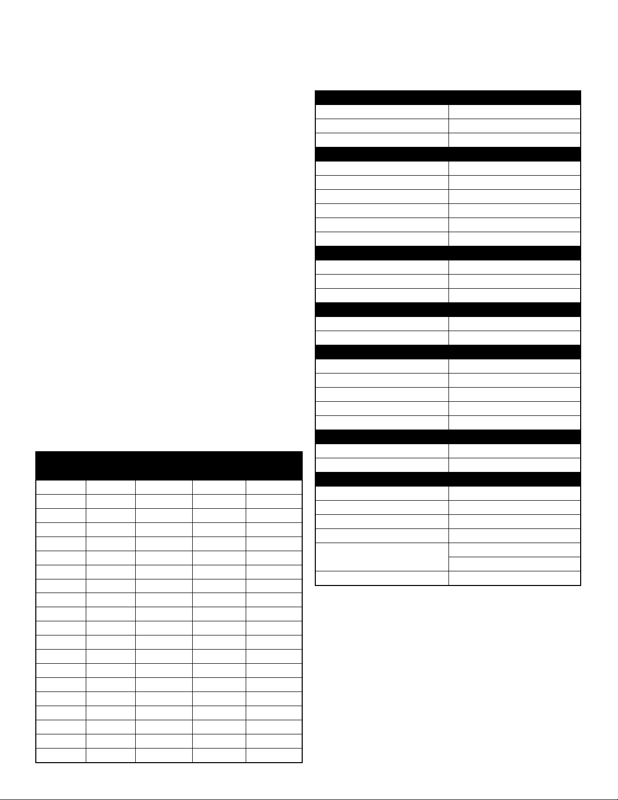
Valve Specifications
Valve material Fiber-reinforced ploymer
Inlet/Outlet 3/4” - 1” NPT, BSP, Sweat
Cycles Up to 5 cycles
Flow rates (50 psi Inlet) - Valve Alone (GPM)
Piston Standard Upflow
Continuous 21
Peak (25 psi drop) 26
Cv (flow at 1 psi drop) 5.5
Max. backwash (25 psi drop) 17
Max. Rapid Rinse (25 psi drop) 10
Regeneration
Downflow/Upflow Upflow only
Adjustable cycles Yes
Time available 199 minutes per cycle
Meter Information
Meter accuracy +1/-5% (.25 - 15GPM)
Meter capacity Range (gal). 1 - 60,000
Dimensions
Distributor pilot 1.05”
Drain line 1/2” NPT Quick Connect
Brine line 3/8” Quick Connect
Mounting base 2-1/2” NPSM
Height from top of tank 6.37”
Typical Applications
Water softener 6” - 16” diameter
Filters 6” - 16” diameter
Additional Information
Injector brine system 1610
Electrical rating 24 VAC, 50/60 Hz
Max. VA 15
Estimated shipping weight 11 lbs.
Pressure Hydrostatic: 300 psi
Working: 20 - 125 psi
Temperature Range 34° - 110° F (1° - 43° C)
Job Specitication Sheet Valve Specifications
Tank
Diameter
Rein Volume Injector
Size
BLFC
Size
US (FT3) Metric (Liters)
8 0.75 20 #00 0.125
9 25 #00 0.125
9 1.00 30 #00 0.125
10 1.25 35 #00 0.125
10 1.50 40 #00 0.125
12 45 #00 0.125
12 1.75 50 #00 0.125
12 2.00 55 #0 0.25
13 60 #0 0.25
13 2.25 65 #0 0.25
14 2.50 70 #1 0.25
14 75 #1 0.25
14 2.75 80 #1 0.25
14 3.00 85 #1 0.25
14 3.25 90 #2 0.50
14 95 #2 0.50
14 3.50 100 #2 0.50
16 3.75 105 #3 0.50
16 110 #3 0.50
16 4.00 115 #3 0.50 The chart to the left is for dealer use only. Use this informa-
tion to configure the system to suit the application.

4
Installation Instructions 6200SXT Upflow
WATER PRESSURE: A minimum of 20 psi (1.4 bar) of water pressure is required for regeneration valve to operate effectively.
ELECTRICAL FACILITIES: An uninterrupted alternating current (A/C) supply is required. Note: Other voltages are available.
Please make sure your voltage supply is compatible with your unit before installation.
EXISTING PLUMBING: Condition of existing plumbing should be free from lime and iron buildup. Piping that is built up heavily
with lime and/or iron should be replaced. If piping is clogged with iron, a separate iron filter unit should be installed ahead
of the water softener.
LOCATION OF SOFTENER AND DRAIN: The softener should be located close to a drain to prevent air breaks and back flow.
BY-PASS VALVES: Always provide for the installation of a by-pass valve if unit is not equipped with one.
CAUTION: Water pressure is not to exceed 125 psi (8.6 bar), water temperature is not to exceed 110°F (43°C), and the unit
cannot be subjected to freezing conditions.
Installation Instructions
1. Place the softener tank where you want to install the unit making sure the unit is level and on a firm base.
2. During cold weather, the installer should warm the valve to room temperature before operating.
3. All plumbing should be done in accordance with local plumbing codes. The pipe size for residential drain line should be
a minimum of 1/2” (13 mm). Backwash flow rates in excess of 7 gpm (26.5 Lpm) or length in excess of 20’ (6 m) require
3/4” (19 mm) drain line. Commercial drain lines should be the same size as the drain line flow control.
4. Cut the distributor tube 1.88” (4.7 cm) below the top of the tank.
5. Lubricate the distributor O-ring seal and tank O-ring seal. Place the main control valve on tank. Note: Only use silicone
lubricant.
6. Solder joints near the drain must be done prior to connecting the Drain Line Flow Control fitting (DLFC). Leave at least
6” (15 cm) between the DLFC and solder joints when soldering pipes that are connected on the DLFC. Failure to do this
could cause interior damage to the DLFC.
7. Teflon tape is the only sealant to be used on the drain fitting. The drain from twin tank units may be run through a
common line.
8. Make sure that the floor is clean beneath the salt storage tank and that it is level.
9. Place approximately 1” (25 mm) of water above the grid plate. If a grid is not utilized, fill to the top of the air check
(Figure 1) in the salt tank. Do not add salt to the brine tank at this time.
10. On units with a by-pass, place in by-pass position. Turn on the main water supply. Open a cold soft
water tap nearby and let run a few minutes or until the system is free from foreign material (usually
solder) that may have resulted from the installation. Once clean, close the water tap.
11. Slowly place the by-pass in service position and let water flow into the mineral tank. When water
flow stops, slowly open a cold water tap nearby and let run until the air is purged from the unit.
12. Plug unit into an electrical outlet. Note: All electrical connections must be connected according
to local codes. Be certain the outlet is uninterrupted.
CAUTION
•Donotexceed125psiwaterpressure
•Donotexceed110°F(43°C)watertemperature
•Donotsubjectunittofreezingconditions
WARNING
ThesystemMUSTbedepressurizedbeforeremovingany
connectionsforservicing.
5
• The Parameter Display displays the current Cycle Step
(BW, BF, RR, etc) during regeneration, and the data
display counts down the time remaining for that cycle
step. While the valve is transferring to a new cycle step,
the display will flash. The parameter display will identify
the destination cycle step (BW, BF, RR, etc) and the data
display will read “----”. Once the valve reaches the cycle
step, the display will stop flashing and the data display will
change to the time remaining. During regeneration, the
user can force the control to advance to the next cycle
step immediately by pressing the extra cycle button.
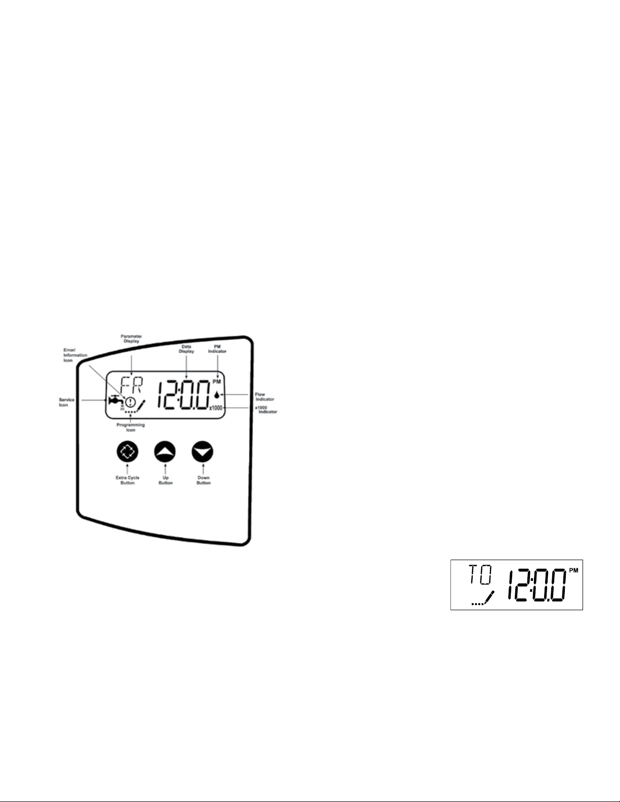
SettingtheTimeofDay
1. Press and hold either the Up or Down buttons until the
programming icon replaces the service icon and the
parameter display reads TD.
2. Adjust the displayed time with the Up and Down buttons.
3. When the desired time is set, press the Extra Cycle
button to resume normal
operation. The unit will
also return to normal
operation after 5 seconds
if no buttons are pressed.
QueuingaRegeneration
1. Press the Extra Cycle button. The service icon will flash to
indicate that a regeneration is queued.
2. To cancel a queued regeneration, press the Extra Cycle
button.
RegeneratingImmediately
Press and hold the Extra Cycle button for five seconds
Start-up Instructions
The water softener/filter should be installed with the inlet, outlet, and drain connections made in accordance with the
manufacturer’s recommendations, and to meet applicable plumbing codes.
Pleaserefertothemanualregenerationpartofthetimeroperationsectioninthismanual.
1. Position the valve to the brine / slow rinse position. Ensure the unit is drawing water from the brine tank (this step may
need to be repeated).
2. Position the valve to backwash. Ensure the drain line flow remains steady for 10 minutes or until the water runs clear
3. Position the valve to the rapid rinse position. Check the drain line flow, and run for 5 minutes or until the water runs clear.
4. Position the valve to the start of the brine tank fill cycle. Ensure water goes into the brine tank at the desired rate. The
brine valve drive cam will hold the valve in this position to fill the brine tank for the first regeneration.
5. Replace control box cover.
6. Put salt in the brine tank.
NOTE:Donotusegranulatedorrocksalt.
Timer Features
FeaturesoftheSXT:
• Power backup that continues to keep time and the
passage of days for a minimum of 48 hours in the event of
power failure. During a power outage, the control goes
into a power-saving mode. It does not monitor water
usage during a power failure, but it does store the volume
remaining at the time of power failure.
• Settings for both valve (basic system) and control type
(method used to trigger a regeneration).
• Day-of-the-Week controls.
• While in service, the display alternates between time of
day, volume remaining or days to regeneration, and tank
in service (twin tank systems only).
• The Flow Indicator ashes when outlet ow is detected.
• The Service Icon ashes if a regeneration cycle has been
queued.
• A Regeneration can be triggered immediately by pressing
the Extra Cycle button for five seconds.

6
Timer Operation
MeterImmediateControl
A meter immediate control measures water usage and
regenerates the system as soon as the calculated system
capacity is depleted. The control calculates the system
capacity by dividing the unit capacity (typically expressed
in grains/unit volume) by the feed water hardness and
subtracting the reserve. Meter Immediate systems
generally do not use a reserve volume. However, in twin
tank systems with soft-water regeneration, the reserve
capacity should be set to the volume of water used during
regeneration to prevent hard water break-through. A Meter
Immediate control will also start a regeneration cycle at the
programmed regeneration time if a number of days equal
to the regeneration day override pass before water usage
depletes the calculated system capacity.
MeterDelayedControl
A Meter Delayed Control measures water usage and
regenerates the system at the programmed regeneration
time after the calculated system capacity is depleted. As
with Meter Immediate systems, the control calculates the
system capacity by dividing the unit capacity by the feed
water hardness and subtracting the reserve. The reserve
should be set to insure that the system delivers treated water
between the time the system capacity is depleted and the
actual regeneration time. A Meter Delayed control will also
start a regeneration cycle at the programmed regeneration
time if a number of days equal to the regeneration day
override pass before water usage depletes the calculated
system capacity.
TimeClockDelayedControl
A Time Clock Delayed Control regenerates the system on a
timed interval. The control will initiate a regeneration cycle
at the programmed regeneration time when the number
of days since the last regeneration equals the regeneration
day override value.
DayoftheWeekControl
This control regenerates the system on a weekly schedule.
The schedule is defined in Master Programming by setting
each day to either “off” or “on.” The control will initiates a
regeneration cycle on days that have been set to “on” at
the specified regeneration time.
ControlOperationDuringRegeneration
During regeneration, the control displays a special
regeneration display. In this display, the control shows the
current regeneration step number the valve is advancing
to, or has reached, and the time remaining in that step. The
step number that displays flashes until the valve completes
driving to this regeneration step position. Once all
regeneration steps are complete the valve returns to service
and resumes normal operation.
Pressing the Extra Cycle button during a regeneration cycle
immediately advances the valve to the next cycle step
position and resumes normal step timing.
ControlOperationDuringProgramming
The control only enters the Program Mode with the valve in
service. While in the Program Mode, the control continues
to operate normally monitoring water usage and keeping
all displays up to date. Control programming is stored in
memory permanently, eliminating the need for battery
backup power.
ManuallyInitiatingaRegeneration
1. When timer is in service, press the Extra Cycle button for 5
seconds on the main screen.
2.
The timer advances to Regeneration Cycle Step #1 (brine
draw & slow rinse), and begins programmed time count
down.
3. Press the Extra Cycle button once to advance valve to
Regeneration Cycle Step #2 (backwash).
4. Press the Extra Cycle button once to advance valve to
Regeneration Cycle Step #3 (rapid rinse).
5. Press the Extra Cycle button once to advance valve to
Regeneration Cycle Step #4 (brine refill).
6. Press the Extra Cycle button once more to advance the
valve back to in service.
NOTE: If the unit is a filter, the cycle step order may change.
NOTE: A queued regeneration can be initiated by pressing the Extra Cycle
button. To clear a queued regeneration, press the Extra Cycle button
again to cancel. If regeneration occurs for any reason prior to the delayed
regeneration time, the manual regeneration request shall be cleared.
ControlOperationDuringaPowerFailure
The SXT includes integral power backup. In the event of
power failure, the control shifts into a power-saving mode.
The control stops monitoring water usage, and the display
and motor shut down, but it continues to keep track of the
time and day for a minimum of 48 hours.
The system configuration settings are stored in a non-volatile
memory and are stored indefinitely with or without line
power. The Time of Day flashes when there has been a
power failure. Press any button to stop the Time of Day from
flashing.
If power fails while the unit is in regeneration, the control will
save the current valve position before it shuts down. When
power is restored, the control will resume the regeneration
cycle from the point where power failed. Note that if power
fails during a regeneration cycle, the valve will remain in
it’s current position until power is restored. The valve system
should include all required safety components to prevent
overflows resulting from a power failure during regeneration.
The control will not start a new regeneration cycle without
line power. If the valve misses a scheduled regeneration due
to a power failure, it will queue a regeneration. Once power
is restored, the control will initiate a regeneration cycle the
next time that the Time of Day equals the programmed
regeneration time. Typically, this means that the valve will
regenerate one day after it was originally scheduled. If the
treated water output is important and power interruptions
are expected, the system should be setup with a sufficient
reserve capacity to compensate for regeneration delays.
ValvePositions
The position label affixed to the brine cam indicates the
cycles and service positions of the control valve.

7
Master Programming Mode Chart
MasterProgrammingOptions
Abbreviation Parameter Option
Abbreviation Options
DF Display Format GAL Gallons
Ltr Liters
VT Valve Type
df1b Standard Downflow/Upflow Single Backwash
df2b Standard Downflow/Upflow Double Backwash
Fltr Filter
UFbF Upflow Brine First (use for 6200 upflow softener valve)
UFtr Upflow Filter (used for 6200 upflow filter valve)
CT Control Type
Fd Meter (Flow) Delayed
Fl Meter (Flow) Immediate
tc Time Clock
d AY Day of Week
NT Number of Tanks 1 Single Tank System
C Unit Capacity Unit Capacity (Grains)
H Feed Water Hardness Hardness of Inlet Water
RS Reserve Selection SF Percentage Safety Factor
rc Fixed Reserve Capacity
SF Safety Factor Percentage of the system capacity to be used as
a reserve
RC Fixed Rate Capacity Fixed volume to be used as a reserve
DO Day Override The system’s day override setting
RT Regen Time The time of day the system will regenerate
BW, BD, RR, BF Regen Cycle Step Times
The time duration for each regeneration step. Ad-
justable from OFF and 0-199 minutes.
NOTE: If “Othe” is chosen under “Valve Type,” then
R1, R2, R3, etc, will be displayed instead.
D1, D2, D3, D4, D5,
D6 & D7 Day of Week Settings Regeneration setting (On or OFF) for each day of
the week on day-of-week systems.
CD Current Day The Current day of the week.
FM Flow Meter Type
t0.7 3/4” Turbine Meter
P0.7 3/4” Paddle Wheel Meter
t1.0 1” Turbine Meter
P1.0 1” Paddle Wheel Meter
t1.5 1.5” Turbine Meter
P1.5 1.5” Paddle Wheel Meter
Gen Generic or Other Meter
K Meter Pulse Setting Meter Pulses per gallon for generic/other flow
meter
NOTES:
Someitemsmaynotbeshowndependingontimerconguration.
ThetimerwilldiscardanychangesandexitMasterProgrammingModeifanybuttonisnotpressedforsixtyseconds.
CAUTION:BeforeenteringMasterProgramming,pleasecontactyourlocalprofessionalwaterdealer.

8
Master Programming Mode
When the Master Programming Mode is entered, all
available option setting displays may be viewed and set
as needed. Depending on current option settings, some
parameters cannot be viewed or set.
SettingtheTimeofDay
1. Press and hold either the Up or Down buttons until the
programming icon replaces the service icon and the
parameter display reads TD.
2. Adjust the displayed time with the Up and Down buttons.
3. When the desired time is set, press the Extra Cycle button
to resume normal operation. The unit will also return
to normal operation after 5 seconds if no buttons are
pressed.
EnteringMasterProgrammingMode
Set the Time Of Day display
to 12:01 P.M. Press the Extra
Cycle button (to exit Setting
Time of Day mode). Then
press and hold the Up and
Down buttons together until the programming icon replaces
the service icon and the Display Format screen appears.
ExitingMasterProgrammingMode
Press the Extra Cycle button to accept the displayed settings
and cycle to the next parameter. Press the Extra Cycle
button at the last parameter to save all settings and return
to normal operation. The control will automatically disregard
any programming changes and return to normal operation
if it is left in Master Programming mode for 5 minutes without
any keypad input.
Resets:
SoftReset: Press and hold the Extra Cycle and Down buttons
for 25 seconds while in normal Service mode. This resets all
parameters to the system default values, except the volume
remaining in meter immediate or meter delayed systems
and days since regeneration in the time clock system.
MasterReset:Hold the Extra Cycle button while powering up
the unit. This resets all of the parameters in the unit. Check
and verify the choices selected in Master Programming
Mode.
1.DisplayFormat(DisplayCodeDF)
This is the first screen that appears when entering Master
Programming Mode. The Display Format setting specifies
the unit of measure that will be used for volume and how
the control will display the Time of Day. This option setting
is identified by “DF” in the upper left hand corner of the
screen. There are three possible settings:
CAUTION: Before entering Master Programming, please contact your local professional water dealer.
Display Format Setting Unit of Volume Time Display
GAL U.S. Gallons 12-Hour AM/PM
Ltr Liters 24-Hour
225
2.ValveType(DisplayCodeVT)
Press the Extra Cycle button. Use this display to set the Valve
Type. The Valve Type setting specifies the type of cycle
that the valve follows during regeneration. Note that some
valve types require that the valve be built with specific
subcomponents. Ensure the valve is configured properly
before changing the Valve Type setting. This option setting
is identified by “VT” in the upper left hand corner of the
screen. There are 2 possible settings:
3.ControlType(DisplayCodeCT)
Press the Extra Cycle button. Use this display to set the
Control Type. This specifies how the control determines when
to trigger a regeneration. For details on how the various
options function, refer to the “Timer Operation” section of
this service manual. This option setting is identified by “CT” in
the upper left hand corner of the screen.
There are four possible settings:
Meter Delayed: Fd
Meter Immediate: FI
Time Clock: tc
Day of Week: dAY
4.NumberofTanks(DisplayCodeNT)
Press the Extra Cycle button. Use this display to set the
Number of Tanks in your system. This option setting is
identified by “NT” in the
upper left hand corner of the
screen. There are two possible
settings:
Single Tank System: 1
Abbreviation Parameter
df1b Standard Downflow/Upflow Single Backwash
df2b Standard Downflow/Upflow Double Backwash
Fltr Filters
UFbF Upflow Brine First (used for 6200 upflow softener valve)
UFtr Upflow Filter to be used with 6200 upflow backwashing
filter valve

identified by “SF” in the
upper left hand corner of the
screen. Use the Up and Down
buttons to adjust the value
from 0 to 50% as needed.
9.FixedReserveCapacity(DisplayCodeRC)
Press the Extra Cycle button. Use this display to set the
Reserve Capacity. This setting specifies a fixed volume that
will be held as a reserve. The reserve capacity cannot be set
to a value greater than one-half of the calculated system
capacity. The reserve capacity is a fixed volume and does
not change if the unit capacity or feed water hardness are
changed. This option setting
is identified by “RC” in the
upper left-hand corner of
the screen. Use the Up and
Down buttons to adjust the
value as needed.
10.DayOverride(DisplayCodeDO)
Press the Extra Cycle button. Use this display to set the Day
Override. This setting specifies the maximum number of days
between regeneration cycles. If the system is set to a timer-
type control, the day override setting determines how often
the system will regenerate. A metered system will regenerate
regardless of usage if the days since last regeneration cycle
equal the day override setting. Setting the day override
value to “OFF” disables this
function. This option setting
is identified by “DO” in the
upper left hand corner of
the screen. Use the Up and
Down buttons to adjust the
value as needed.
11.RegenerationTime
Press the Extra Cycle button. Use this display to set the
Regeneration Time. This setting specifies the time of day
the control will initiate a delayed, manually queued, or
day override triggered regeneration. This option setting
is identified by “RT” in the
upper left hand corner of the
screen. Use the Up and Down
buttons to adjust the value as
needed.
5.UnitCapacity(DisplayCodeC)
Press the Extra Cycle button. Use this display to set the Unit
Capacity. This setting specifies the treatment capacity of
the system media. Enter the capacity of the media bed in
grains of hardness when configuring a softener system, and
in the desired volume capacity when configuring a filter
system. This option setting is identified by “C” in the upper
left hand corner of the screen. The Unit Capacity parameter
is only available if the
control type has been set to
one of the metered options.
Use the Up and Down
buttons to adjust the value
as needed.
6.FeedwaterHardness(DisplayCodeH)
Press the Extra Cycle button. Use this display to set the Feed
Water Hardness. Enter the feed water hardness in
grains per unit volume for softener systems, or 1 for filter
systems. This option setting is identified by “H” in the
upper left hand corner of the screen. The feedwater
hardness parameter is only
available if the control type
has
been set to one of the
metered options. Use the Up
and Down buttons to adjust
the value as needed.
7.ReserveSelection(DisplayCodeRS)
Press the Extra Cycle button. Use this display to set the Safety
Factor. Use this display to select the type of reserve to be
used in your system. This setting is identified by “RS” in the
upper left-hand corner of the screen. The reserve selection
parameter is only available if the control type has been set
to one of the metered options.
There are two possible settings.
8.SafetyFactor(DisplayCodeSF)
Press the Extra Cycle button. Use this display to set the
Safety Factor. This setting specifies what percentage of
the system capacity will be held as a reserve. Since this
value is expressed as a percentage, any change to the
unit capacity or feedwater hardness that changes the
calculated system capacity will result in a corresponding
change to the reserve volume. This option setting is
9
Master Programming Mode
CAUTION: Before entering Master Programming, please contact your local professional water dealer.
Range:1-999,900graincapacity
Range:4-199hardness
FS Safety Factor
rc Fixed Reserve Capacity
Range:0-50%
Range:0-halfthecalculated
225
Range:Off-99days

15.CurrentDay(DisplayCodeCD)
Press the Extra Cycle button. Use this display to set the
current day on systems that have been configured as Day
of Week controls. This setting is identified by “CD” in the
upper left-hand corner of the
screen. Use the Up and Down
buttons to select from Day 1
through Day 7.
16.FlowMeterType(Display
CodeFM)
Press the Extra Cycle button. Use this display to set the type
of flow meter connected to the control. This option setting
is identified by “FM” in the
upper left-hand corner of the
screen. Use the Up and Down
buttons to select one of the 7
available settings.
16.MeterPulseSetting(DisplayCodeK)
Press the Extra Cycle button. Use this display to specify
the meter pulse setting for a non-standard flow meter. This
option setting is identified by “K” in the upper left-hand
corner of the screen. Use
the Up and Down buttons to
enter the meter constant in
pulses per unit volume.
17. Press the Extra Cycle button to save all settings and exit
Master Programming Mode.
10
CAUTION: Before entering Master Programming, please contact your local professional water dealer.
Master Programming Mode
12.RegenerationCycleStepTimes
Press the Extra Cycle button. Use this display to set the
Regeneration Cycle Step Times. The different regeneration
cycles are listed in sequence based on the valve
type selected for the system, and are identified by an
abbreviation in the upper left-hand corner of the screen.
The abbreviations used are listed below. If the system
has been configured with the “OTHER” valve type, the
regeneration cycles will be identified as R1, R2, R3, R4, R5,
and R6. Each cycle step time can be set from 0 to 199
minutes, or “OFF.” Setting a cycle step to “OFF” will disable
all of the following steps. Setting a cycle step time to 0 will
cause the control to skip that step during regeneration, but
keeps the following steps available. Use the Up and Down
buttons to adjust the value as needed. Press the Extra Cycle
button to accept the current setting and move to the next
parameter.
13.DayofWeekSettings
Press the Extra Cycle button. Use this display to set the
regeneration schedule for a system configured as a Day of
Week control. The different days of the week are identified
as D1, D2, D3, D4, D5, D6, and D7 in the upper left-hand
corner of the display. Set the value to “ON” to schedule
a regeneration or “OFF” to skip regeneration for each
day. Use the Up and Down buttons to adjust the setting as
needed. Press the Extra Cycle button to accept the setting
and move to the next day. Note that the control requires at
least one day to be set to
“ON.” If all 7 days are set to
“OFF”, the unit will return to
Day One until one or more
days are set to “ON.”
BD
60
BW
10
RR
10
BF
12
Range:0-199minutes
Cycle Step Abbreviation
BD Brine Draw
BW Backwash
RR Rapid Rinse
BF Brine Refill
SV Service
t0.7 Fleck 3/4” Turbine Meter
P0.7 Fleck 3/4” Paddle Wheel Meter
t1.0 Fleck 1” Turbine Meter
P1.0 Fleck 1” Paddle Wheel Meter
t1.5 Fleck 1-1/2” Turbine Meter
P1.5 Fleck 1-1/2” Paddle Wheel Meter
GEn Generic/Other Meter
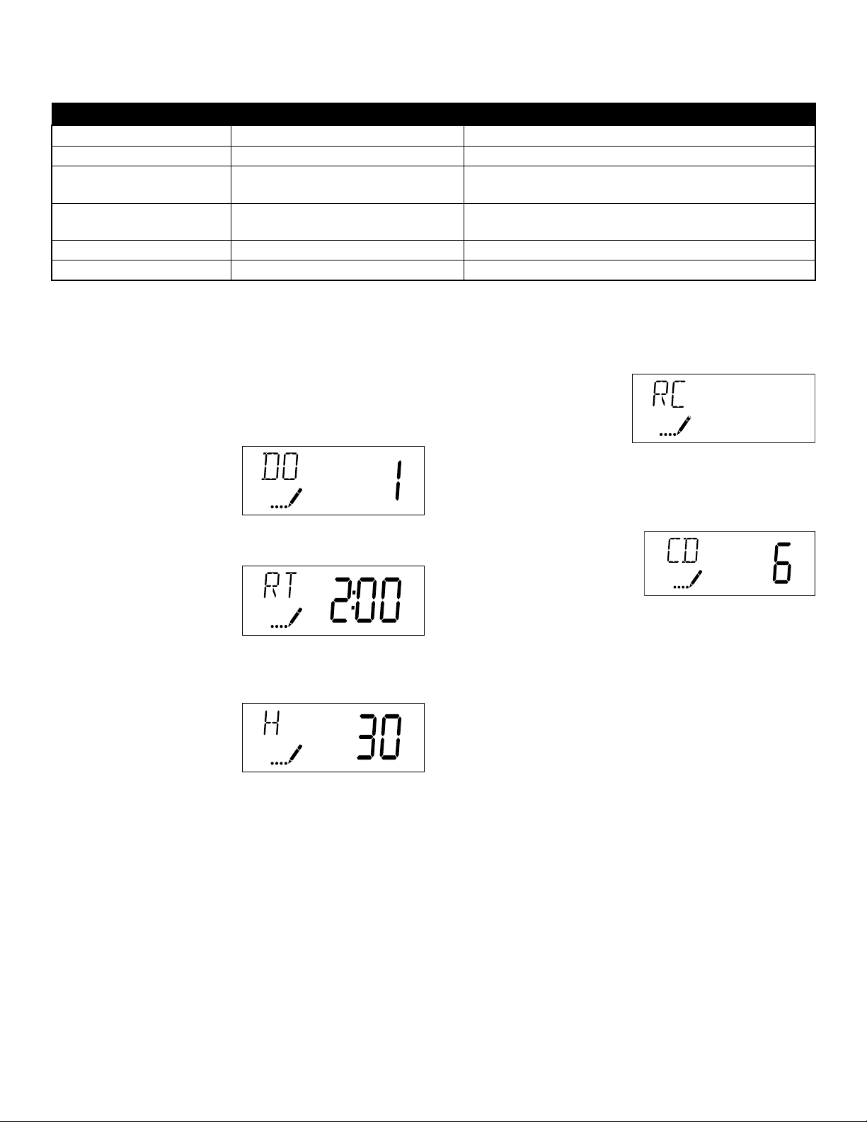
5. Press the Extra Cycle
button. Use this display
to adjust the Fixed
Reserve Capacity. This
option setting is identified
by “RC” in the upper
left-hand Corner of the
screen.
6. Press the Extra Cycle
button. Use this display to
set the Current Day of the
Week. This option setting
is identified by “CD” in the
upper left hand corner of
the screen.
7. Press the Extra Cycle button
to end User Programming Mode.
11
CAUTION: Before entering Master Programming, please contact your local professional water dealer.
User Programming Mode
UserProgrammingModeOptions
Abbreviation Parameter Description
DO Day Override The timer’s day override setting
RT Regeneration Time The time of day that the system will regenerate (meter
delayed, timeclock and day-of-week systems)
H Feed Water Hardness The hardness of the inlet water - used to calculate
system capacity for metered systems
RC Reserve Capacity The fixed reserve capacity
CD Current Day The current day of week
NOTES:
Someitemsmaynotbeshowndependingontimerconguration.
ThetimerwilldiscardanychangesandexitUserModeifanybuttonisnotpressedforsixtyseconds.
UserProgrammingModeSteps
1. Press the Up and Down buttons for five seconds while in
service, and the time of day is NOT set to 12:01 PM.
2. Use this display to adjust
the Day Override. This
option setting is identified
by “DO” in the upper
left hand corner of the
screen.
3. Press the Extra Cycle
button. Use this display to
adjust the Regeneration
Time. This option setting
is identified by “RT” in the
upper left hand corner of
the screen.
4. Press the Extra Cycle
button. Use this display
to adjust the Feed Water
Hardness. This option
setting is identified by “H”
in the upper left hand
corner of the screen.
Range:4-199hardness
225

5. Press the Up button. Use
this display to view the
Volume Used since the
last regeneration cycle.
This option setting is
identified by “VU” in the
upper left hand corner of
the screen.
6. Press the Up button. Use
this display to view the
Reserve Capacity. This
option setting is identified
by “RC” in the upper
left hand corner of the
screen.
7. Press the Up button. Use
this display to view the
Software Version. This
option setting is identified
by “SV” in the upper
left hand corner of the
screen.
8. Press the Extra Cycle button to end Diagnostic
Programming Mode.
12
Diagnostic Programming Mode
DiagnosticProgrammingModeSteps
1. Press the Up and Extra Cycle buttons for five seconds
while in service.
2. Use this display to view
the current Flow Rate.
This option setting is
identified by “FR” in the
upper left hand corner
of the screen.
3. Press the Up button. Use
this display to view the
Peak Flow Rate since
the last regeneration
cycle. This option setting
is identified by “PF” in the
upper left hand corner of
the screen.
4. Press the Up button. Use
this display to view the
Hours in Service since
the last regeneration
cycle. This option setting
is identified by “HR” in the
upper left hand corner of
the screen.
DiagnosticProgrammingModeOptions
Abbreviation Parameter Description
FR Flow Rate Displays the current outlet flow rate
PF Peak Flow Rate Displays the highest flow rate measured since the last regeneration
HR Hours in Service Displays the total hours that the unit has been in service
VU Volume Used Displays the total volume of water treated by the unit
RC Reserve Capacity Displays the system’s reserve capacity calculated from the system
capacity, feed water hardness, and safety factor
SV Software Version Displays the software version installed on the controller
NOTES:
Someitemsmaynotbeshowndependingontimerconguration.
ThetimerwillexitDiagnosticModeafter60secondsifnobuttonsarepressed.
PresstheExtraCyclebuttontoexitDiagnosticModeatanytime.
13
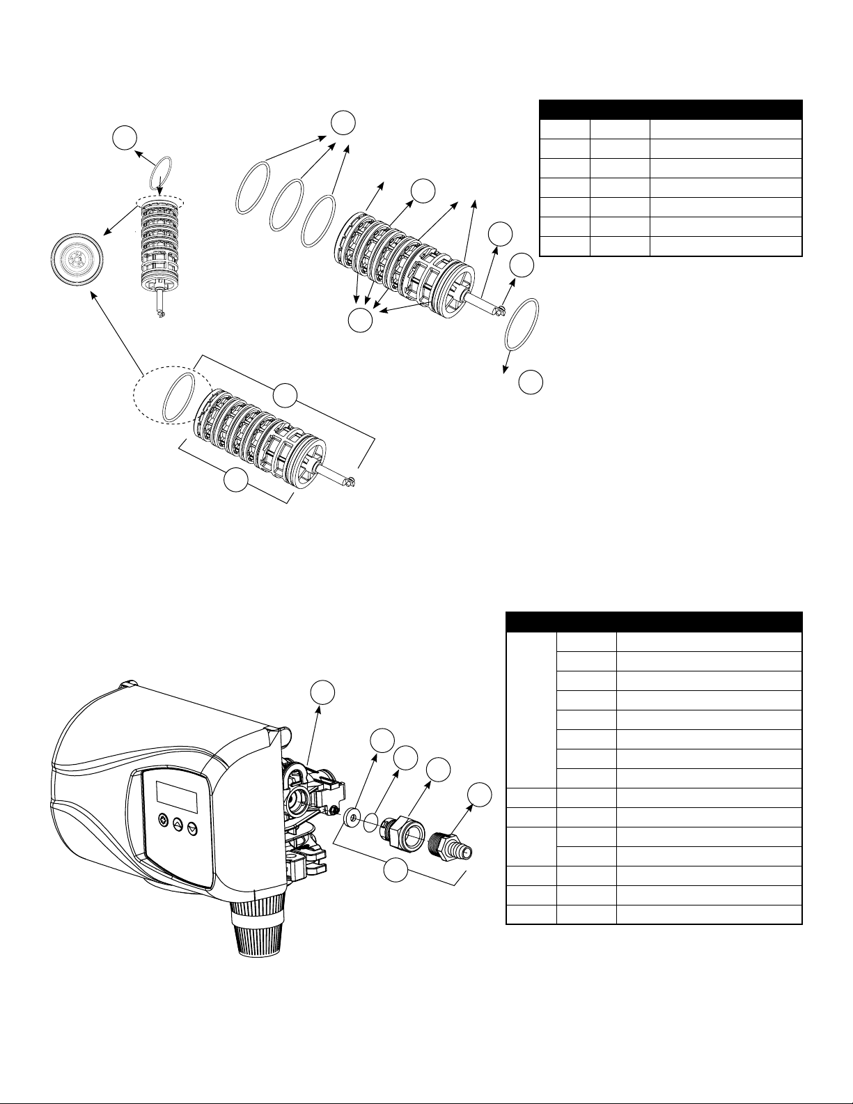
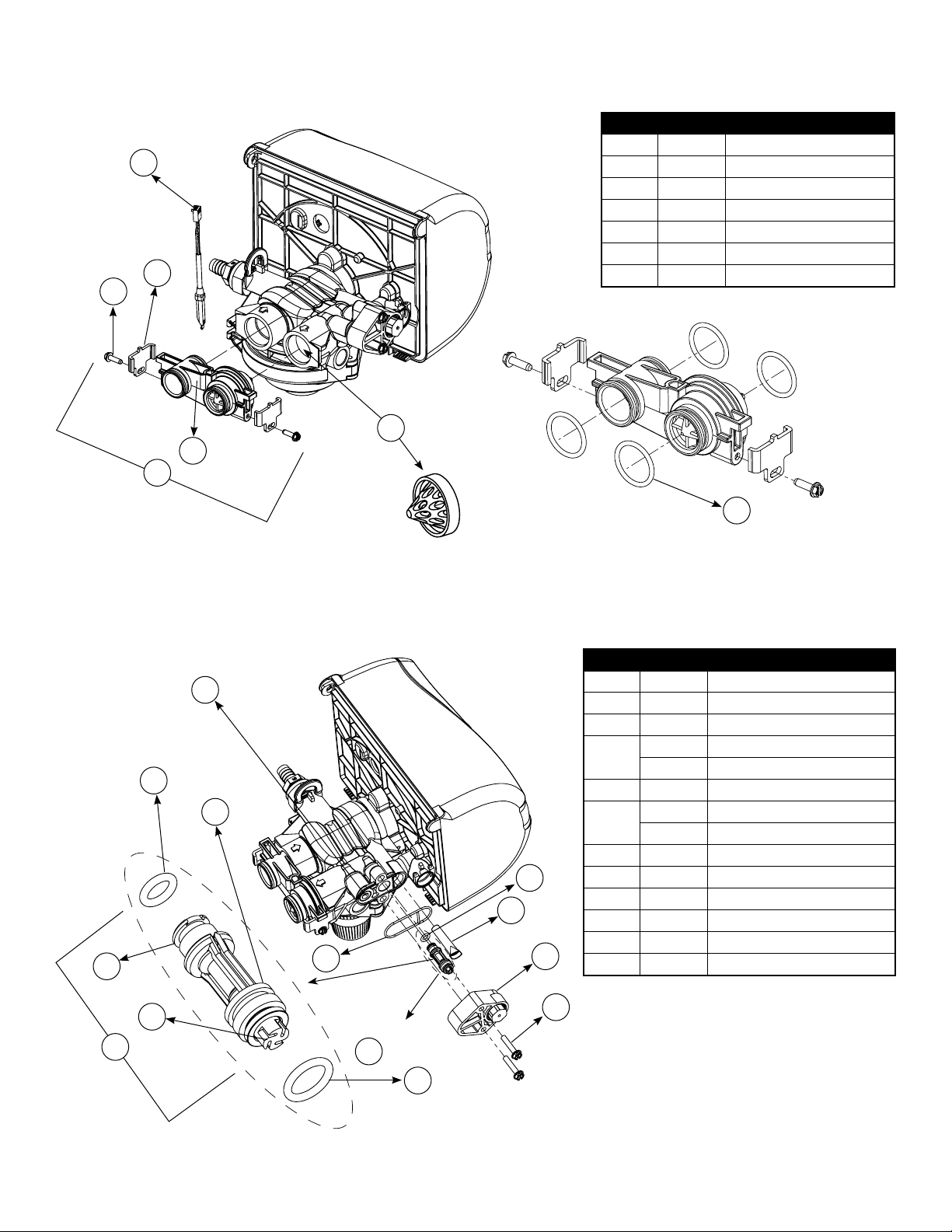
Dwg # Part # Part Description
7 61799-01 Cartridge Assembly with Piston
76 11335 Screw, 4-40X3/16
97 16394 O-Ring, 029
98 13287 O-Ring, 123
99 61799 Seal and Spacer Cartridge
100 42920 Piston
101 19984 Piston Rod
Dwg # Part # Part Description
61
12085 Washer, Flow, 1.2 GPM
12086 Washer, Flow, 1.50 GPM
12087 Washer, Flow, 2.0 GPM
12088 Washer, Flow, 2.4 GPM
12089 Washer, Flow, 3.0 GPM
12090 Washer, Flow, 3.5 GPM
12091 Washer, Flow, 4.0 GPM
12092 Washer, Flow, 5.0 GPM
62 11183 O-Ring, 017
63 11385-01 Adapter, Fitting, DLFC
88 13308 Hose Barb, Straight, DLFC,1/2"
12388 Hose Barb, 90 Deg, DLFC,1/2"
89 60705-XX DLFC Assembly, XX GPM For < 7 GPM
60706-XX DLFC Assembly, XX GPM For > 7 GPM
19 18312 Retainer, Drain
6200 Service Kits – Piston and Cartridge Assembly
6200 Service Kits – Drain Line Flow Control Kits
7
99
89
19
61
62 63
88
O-Ring 98
O-Ring 97
O-Ring 97
O-Ring 97
Blank
Blank
101
76
100
B
A
1
3
4
4
3
2
1
2
THISDOCUMENTIS SOLELY THE PROPERTY OF PENTAIR
WATERTREATMENT.REPRODUCTION, USE DISCLOSURE, OR
TRANSMISSIONOFTHIS DOCUMENT OR DETAILS CONTAINED
HEREIN,INPART OR IN WHOLE, IS PROHIBITED WITHOUT
THEWRITTENCONSENT OF PENTAIR WATER TREATMENT
ENGINEERING.THISDOCUMENT AND ANY COPIES SHALL BE
RETURNEDTOPENTAIR WATER TREATMENT UPON WRITTEN
REQUEST.
TITLE
SIZE
SCALE
SHEET4 OF 4
DWGNO.
REV
Pentair Residential
Filtration
CHECKED
APPROVED
APPROVALS
DATE
THIRDANGLE
PROJECTION
DRAWN
SOLIDWORKSFORMAT
LEVEL I
LEVEL II
LEVEL III
CRITICALITY SYMBOLS PER QPSP-001.2
DATEAND TIME
D
1:1
5
5
D
C
6
7
8
6
7
8
B
C
D
REVISIONS
DATE
APP'D
DESCRIPTION
REV.
ECN
ZONE
_
A
THISDRAWING MUST BE COMPARED TO THE ERP SYSTEM TO ENSURE CORRECT REVISION LEVEL PRIOR TO USE.
LASTSAVED IN SMARTEAM:
DONOTSCALE DRAWING. DIMS. ARE IN INCHES [mm]
INTERPRETDIMSAND TOLERANCES PER ASME Y14.5M -1994
UNLESSOTHERWISESPECIFIED:
CORNERFILLETSR.005-.020 [.127-.508]
TOLERANCES:
ANGLES:
1
1PLACE .X:
.015 [0.38]
2PLACE .XX:
.01 [0.3]
3PLACE .XXX:
.005 [0.13]
THECOMPONENT,PART, OR ASSEMBLY DESCRIBED IN THIS DOCUMENT MUST COMPLY WITH THE EU (EUROPEAN UNION) DIRECTIVE:
RoHSDIRECTIVE2002/95/EC,
BR42889

14
Dwg # Part # Part Description
17 13302 O-Ring, 014
12 10141 O-Ring, 010
68
17307 Washer, Flow, 0.125 GPM
12094 Washer, Flow, 0.25 GPM
12095 Washer, Flow, 0.5 GPM
12097 Washer, Flow, 1.0 GPM
15 19334 Retainer, Flow Washer, BLFC
16 19335 Fitting, BLFC,3/8"
20 19625 Nut, Assembly, 3/8" Plastic
95 60422-XX BLFC Assembly, Specify XX=GPM
6200 Service Kits – Brine Line Flow Control Kits
6200 Service Kits – Brine Valve
Dwg # Part # Part Description
17 13302 O-Ring, 014
93 60032 Brine Valve Assembly
52 40055-06 Bracket, Plastic
53 15137 Screw, Hex Washer Head
60 40134 Screw, Self Tap
18
20
16
17
95
12 68
15
17
93 52
53
60
Dwg # Part # Part Description
17 13302 O-Ring, 014
12 10141 O-Ring, 010
68
17307 Washer, Flow, 0.125 GPM
12094 Washer, Flow, 0.25 GPM
12095 Washer, Flow, 0.5 GPM
12097 Washer, Flow, 1.0 GPM
15 19334 Retainer, Flow Washer, BLFC
16 19335 Fitting, BLFC,3/8"
20 19625 Nut, Assembly, 3/8" Plastic
95 60422-XX BLFC Assembly, Specify XX=GPM
Dwg # Part # Part Description
17 13302 O-Ring, 014
93 60032 Brine Valve Assembly
52 40055-06 Bracket, Plastic
53 15137 Screw, Hex Washer Head
60 40134 Screw, Self Tap
15
6200 Service Kits – Injector Assembly
6200 Service Kits – Flow Meter
Dwg # Part # Part Description
91 18276-01 Plug, Injector, Assembly
64 040095 Flow Dispersor
56 40058 Screen, Injector
58 40079-20 Cap, Injector, Regulated, Softener
18277 Cap, Injector Filter
29 18262 Screw, #10-24 X 1
14 040064 Seal, Injector, Softener
18301 Seal, Injector, Filter
66 18275-X Throat, Injector, Specify Size X
65 18274-X Nozzle, Injector, Specify Size X
12 10141 O-Ring, -010
67 18273 Generator, Vortex
13 13771 O-Ring, -012
90 61514-XX Injector Assembly, Specify Size XX
Dwg # Part # Part Description
84 19791-01 Cable, Meter
22 19569 Clip, Flow Meter
24 13314 Screw, Slot Hex, 8-18 X0.6
23 19797 Meter, Assy,3 /4" Dual Port
105 13305 O-Ring, -119
21 14613 Flow Straightener
94 60626 Meter Only, Electronic Turbine
90
65
66
12
91
14
13
29
58
56
64
67
84
24
22
23
21
94
105
Replace with
for filter valve
91
16
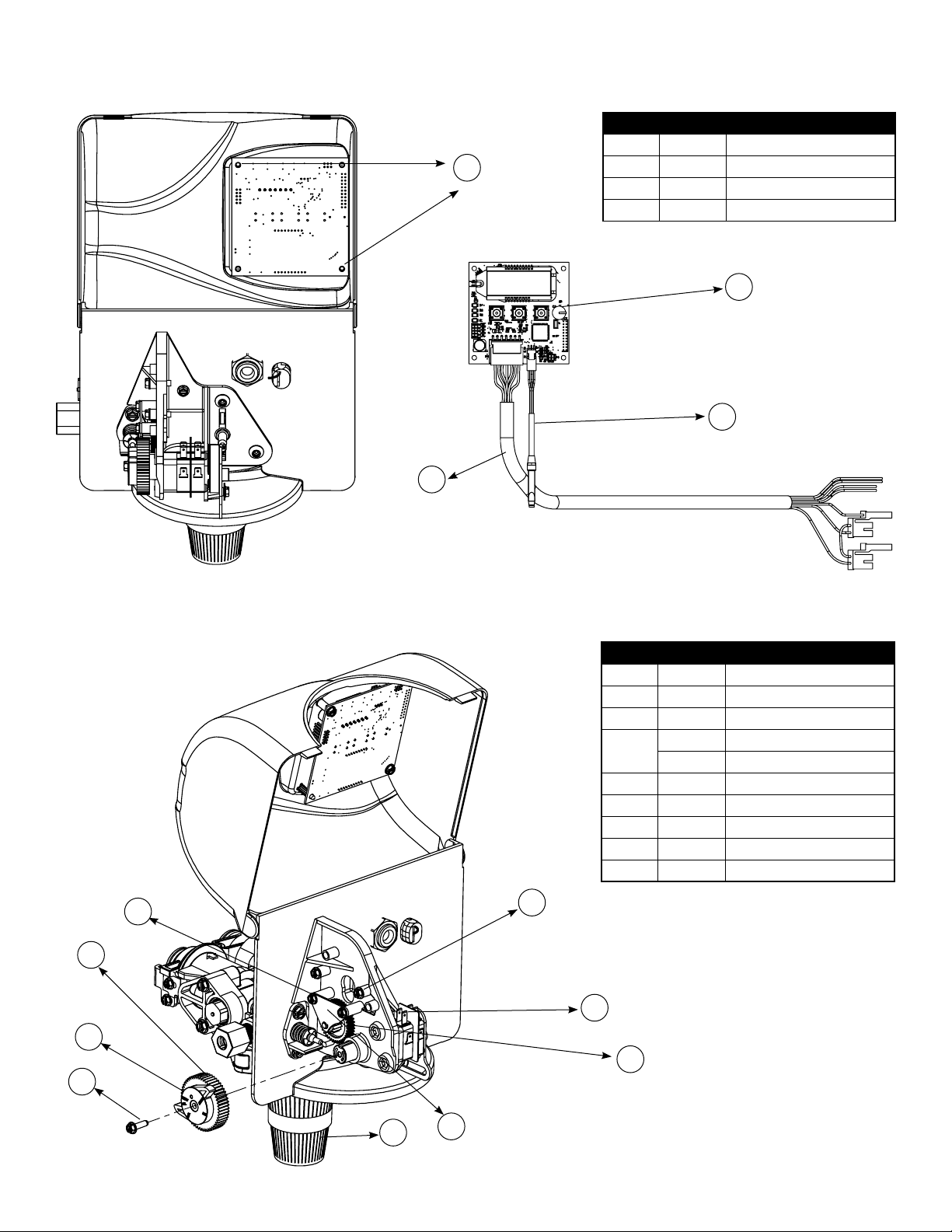
6200 Service Kits – Circuit Board
Dwg # Part # Part Description
82 19474-01 Harness, Power, SXT
84 19791-01 Cable Meter
36 42766-02 Circuit Board, SXT
37 17020 Screw
6200 Service Kits – Other Parts
Dwg # Part # Part Description
37 17020 Screw, Stl Hex, 6-20 X 3/8
51 040050 Screw, Hex Washer
34 42919 Cam, Brine
85 43107 Label, Cam Position, Softener
43121 Label, Cam Position, Filter
24 13314 Screw, Slot, Hex, 8-18 X 0.60
87 18280 Collector, Top, 1"
48 19619 Bracket, Idler
47 43298 Gear Idler
42 10218 Switch, Micro
37
82
37
85
24
87 48
47
42
51
34
84
36

Dwg # Part # Part Description
82 19474-01 Harness, Power, SXT
84 19791-01 Cable Meter
36 42766-02 Circuit Board, SXT
37 17020 Screw
Dwg # Part # Part Description
37 17020 Screw, Stl Hex, 6-20 X 3/8
51 040050 Screw, Hex Washer
34 42919 Cam, Brine
85 43107 Label, Cam Position, Softener
43121 Label, Cam Position, Filter
24 13314 Screw, Slot, Hex, 8-18 X 0.60
87 18280 Collector, Top, 1"
48 19619 Bracket, Idler
47 43298 Gear Idler
42 10218 Switch, Micro
17
Dwg # Part # Part Description
28 19998 Shaft, Drive
27 40057 Screw, Hex Washer Head
26 40254 Clamp, Ring
92 60503 Clamp Ring Assembly
Dwg # Part # Part Description
40 43052-01 Cover, Black
43052-02 Cover, Cream
54 10231 Screw, Slot Hex, 1/4-20 X 1/2
49 19597 Motor, 24V, 50/60 Hz
35 43053-01 Backplate, Black
43053-02 Backplate, Cream
41 19581 Bracket, Drive
43 10302 Insulator, Limit Switch
32 019688 Link, Piston Rod
31 019493 Shaft, Drive
55 13363 Washer
37 17020 Screw, Hex, 6-20 X 3/8
6200 Service Kits – Other Parts Continued
28
27
26
92
40
54
49
41
35
37
55
31
32
43
18
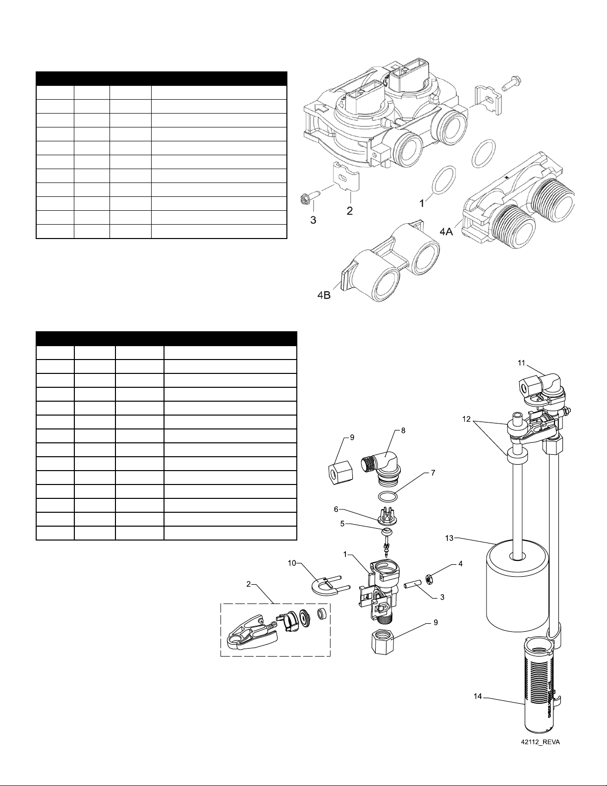
Bypass Valve Assembly & Yokes (Plastic)
2310 Safety Brine Valve
Item No. Quantity Part No. Description
1 2 13305 O-ring, -119
2 2 13255 Clip, Mounting
3 2 13314 Screw, Hex Washer Head, 8-18 x 5/8
4A 1 18706 Yoke, Plastic, 1” NPT
18706-02 Yoke, Plastic, 3/4” NPT
4B 1 13708 Yoke, Brass, 3/4” NPT
13708NP Yoke, 3/4” NPT Nickel Plated
13398 Yoke, Brass, 1” NPT
13398NP Yoke, 1” NPT Nickel Plated
40636 Yoke, 1 1/4” NPT
40636-49 Yoke, 1 1/4” Sweat
Item No. Quantity Part No. Description
1 1 19645 Body, Safety Brine Valve, 2310
2 1 19803 Safety Brine Valve Assembly
3 1 19804 Screw, Socket Hd, Set, 10-24 X .75
4 1 19805 Poppet Assembly, SBV w/O-ring
5 1 19652-01 3RSSHW $VV\, 6%9 Z/2-ULQJ
6 1 19649 Flow Dispenser
7 1 11183 O-ring, -017
8 1 19647 Elbow, Safety Brine Valve
9 2 19625 Nut Assembly, 3/8” Plastic
10 1 18312 Retainer, Drain
11 1 60014 Safety Brine Valve Assembly, 2310
12 2 10150 Grommet, .30 Diameter
13 1 60068-30 Float Assembly, 2310, w/30” Rod
14 1 60002-34 Air Check, #500, 34” Long

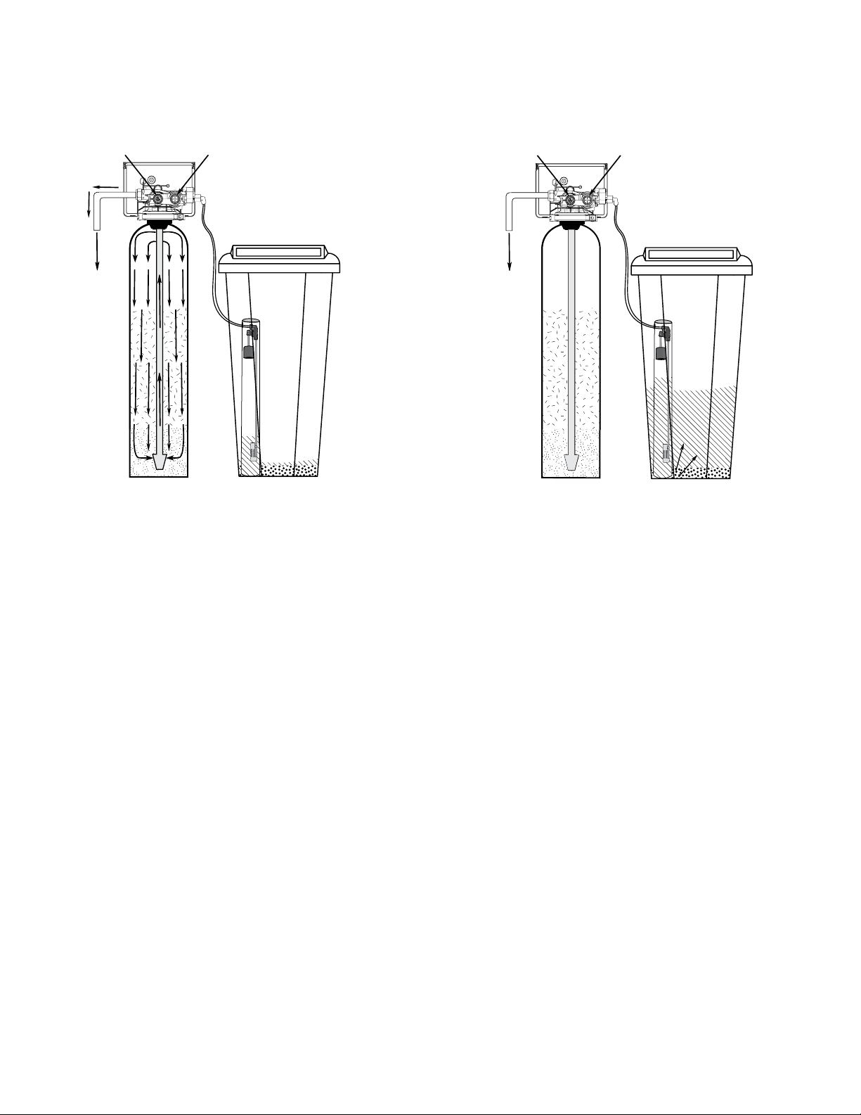
Water Conditioner Flow Diagrams
19
ServicePosition BackwashPosition
BrineRinsePosition SlowRinsePosition
Hard Water Soft Water
To Drain
Hard Water Soft Water
To Drain
Hard Water Soft Water
To Drain
Hard Water Soft Water
To Drain
Hard Water Soft Water
To Drain
Hard Water Soft Water
To Drain
Hard Water Soft Water
To Drain
Hard Water Soft Water
To Drain
Hard Water Soft Water
To Drain
Hard Water Soft Water
To Drain
Hard Water Soft Water
To Drain
Hard Water Soft Water
To Drain
Water Conditioner Flow Diagrams
20
RapidRinsePosition BrineRellPosition
Hard Water Soft Water
To Drain
Hard Water Soft Water
To Drain
Hard Water Soft Water
To Drain
Hard Water Soft Water
To Drain
Hard Water Soft Water
To Drain
Hard Water Soft Water
To Drain
Other manuals for 6200 SXT
1
Table of contents
Popular Control Unit manuals by other brands

Siemens
Siemens VVG44.15-0.4S Technical instructions

Festo
Festo CP-FB13-E Programming and diagnostics manual

BARTEC FEAM
BARTEC FEAM ESAnA Series Instructions for use

Timotion
Timotion TDH18P user manual

tau
tau K120M installation guide

Siemens
Siemens SINUMERIK 828D Turning Software and hardware Service Manual


Danfoss
Danfoss DSV 2 installation guide

tams elektronik
tams elektronik HELIOS.DC manual

GE
GE CompactPCI VMIACC-7055 Series installation guide

Goetze
Goetze 481 SP Assembly and maintenance instructions

Emerson
Emerson Fisher Baumann 24003 instruction manual

Life
Life RG1 24P Instructions for installation, use and maintenance