Festo CP-FB13-E Owner's manual
Other Festo Control Unit manuals
Festo
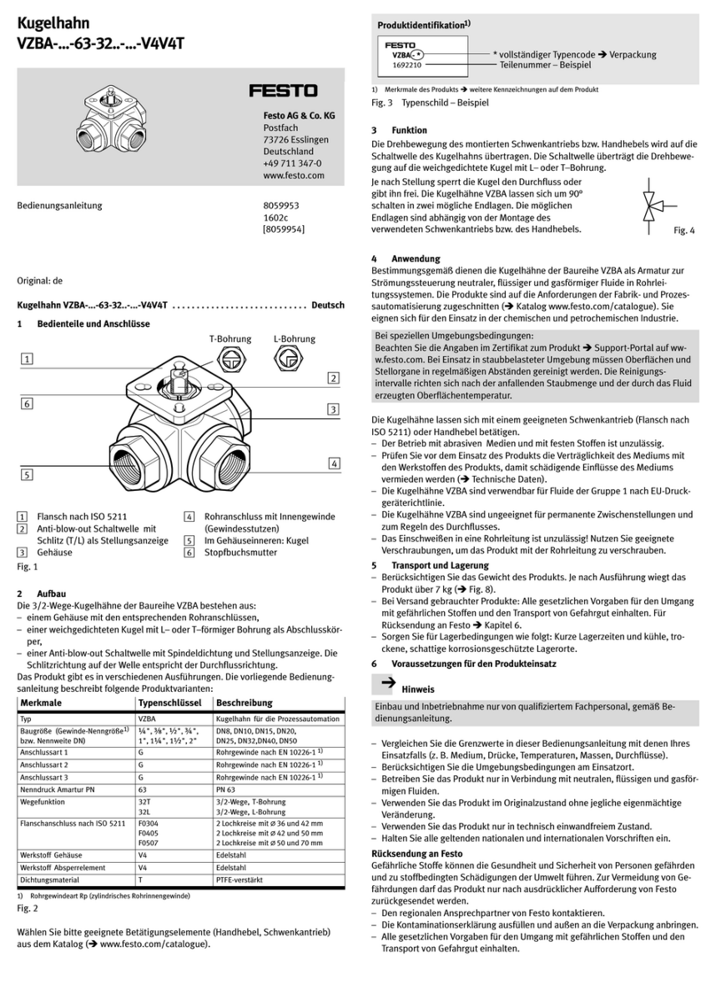
Festo VZBA-x-63-32x-x-V4V4T Series User manual
Festo
Festo VIFB13 Series User manual
Festo
Festo CPX-CM-HPP Operating and installation instructions
Festo
Festo CPX-CM-HPP Parts list manual
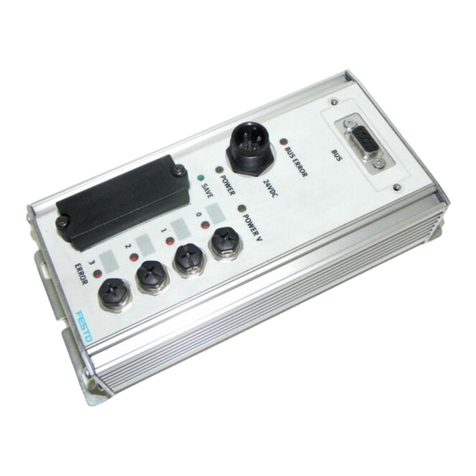
Festo
Festo CP-FB13-E Parts list manual
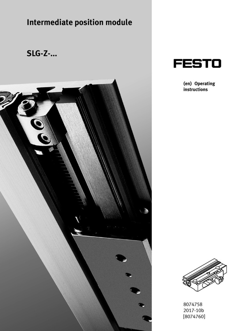
Festo
Festo SLG-Z Series User manual

Festo
Festo VACC-S18-35-K4-1U-EX4ME User manual

Festo
Festo Compact Performance CP-FB6-E Parts list manual
Festo
Festo CPA-SC Series User manual
Festo
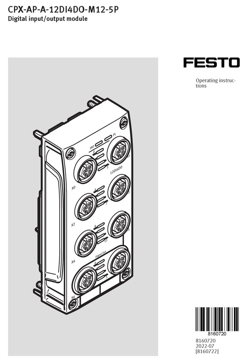
Festo CPX Series User manual
Festo
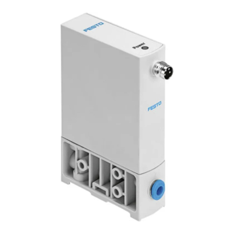
Festo CPX-AP-A-12DI4DO-M12-5P User manual
Festo
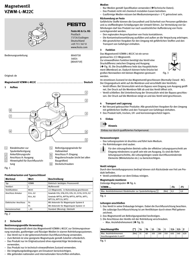
Festo VEAB Series User manual
Festo
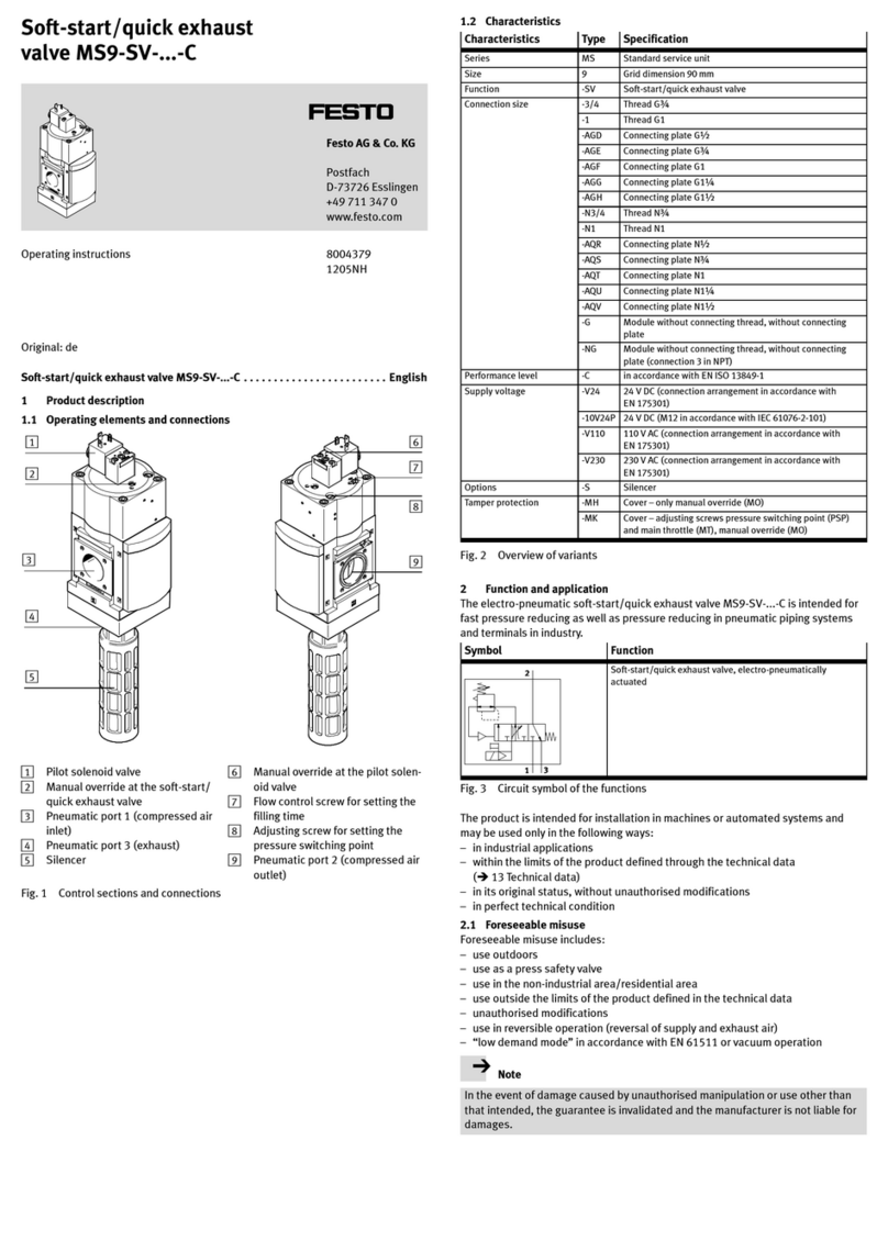
Festo VZWM-L-M22C User manual
Festo
Festo MS9-SV-10V24P User manual
Festo
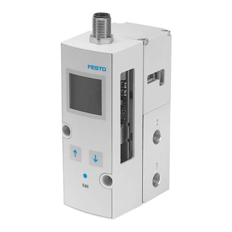
Festo VPPM-6L-L-1-G18-0L6H-V1N-S1C1 User manual
Festo
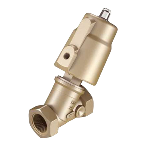
Festo VZXF Series Parts list manual

Festo
Festo CPX Series Parts list manual

Festo
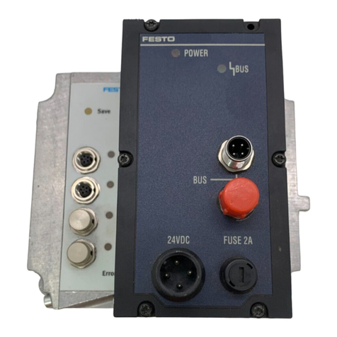
Festo CPX-E-EP User manual
Festo
Festo CP-FB8 Parts list manual
Festo
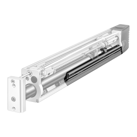
Festo HMP-...-SL Series User manual
Popular Control Unit manuals by other brands

Elo TouchSystems
Elo TouchSystems DMS-SA19P-EXTME Quick installation guide

JS Automation
JS Automation MPC3034A user manual

JAUDT
JAUDT SW GII 6406 Series Translation of the original operating instructions

Spektrum
Spektrum Air Module System manual

BOC Edwards
BOC Edwards Q Series instruction manual

KHADAS
KHADAS BT Magic quick start

Etherma
Etherma eNEXHO-IL Assembly and operating instructions

PMFoundations
PMFoundations Attenuverter Assembly guide

GEA
GEA VARIVENT Operating instruction

Walther Systemtechnik
Walther Systemtechnik VMS-05 Assembly instructions

Altronix
Altronix LINQ8PD Installation and programming manual

Eaton
Eaton Powerware Series user guide
