Waterite Micronizer W-988 User manual
Installation of Replacement Parts
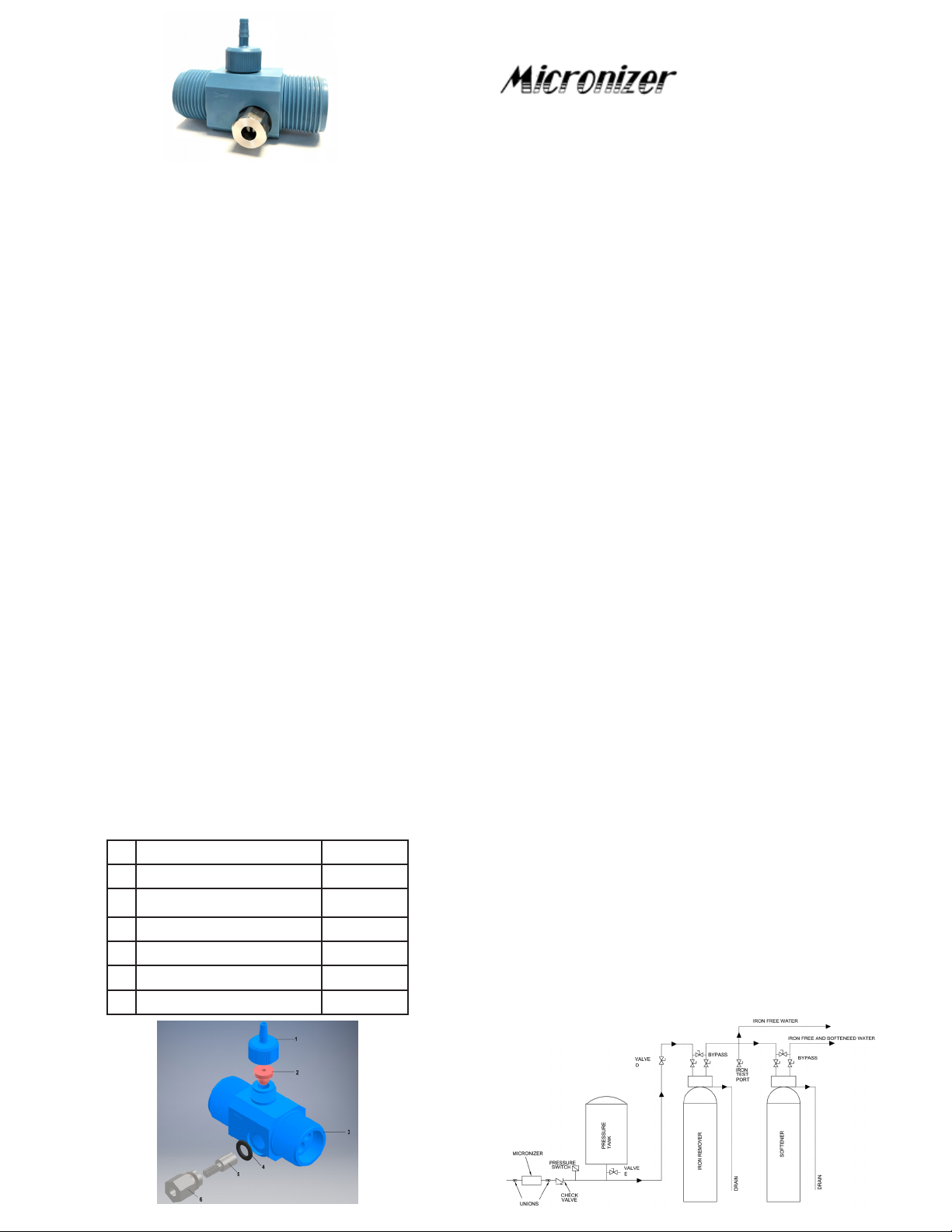
The Waterite Micronizer consists of a high impact Celcon®
plastic body containing two water passages. The water passage
closest to the check valve (2) contains built-in convergent and
divergent cones forming a venturi. The venturi causes air to be
drawn into the water stream when water is owing.
The second water passage acts as a by-pass. The percentage
of water ow allowed through the by-pass assembly is regulated
by the valve gate (5) and gate retainer (6) assembly. This in
turn regulates the amount of air drawn into the water stream
through the venturi. Turning the valve gate screw clockwise
forces more water through the venturi passage. This in turn
causes more air to be drawn into the water stream. In the
event that parts must be replaced, this can be accomplished by
following a few simple instructions:
1. To replace die rubber check valve (2), wet the check valve
with water ONLY and install it in the main body. Thread
the cap down snugly by hand. Do not over tighten.
Failure to lubricate the rubber properly will cause the valve
to twist inside the cap and will result in leakage of water
through the valve. If this should occur, remove the valve,
relubricate, and install it.
2. To replace the o-ring or valve gate/ gate retainer assembly,
start by lubricating the rubber o-ring with water or a silicone
oil. Carefully insert the o-ring into its seat in die bottom of
the hole in the main body. Thread the valve gate fully into
the gate retainer. Thread the gate retainer into the main
body by hand to a snug t. With the use of a suitable tool
(wrench or pliers), turn the gate retainer another 1/4 turn
into the main body. Do not over tighten.
Note: Topreventleakageatthe1”NPTthreads,useTeon
tape during the assembly of the Micronizer to the plumbing
system. Care should be taken when wrapping the tape over
the threads to ensure that no tape enters the Micronizer and
blocks the venturi.
W-988 Micronizer Parts P/N
1 Knurled Cap, Plastic WA14051
2 Check Valve M-005 WA14047
3 Main Body – blue M-988 WA14056
4 O-ring M-011 WA14059
5 Valve Gate, Stainless WA14054
6 Gate Retainer, Stainless WA14041
Waterite ® Model W-988
Installation of your Micronizer in a
Private Well Water System
1. Start Up Procedure
See gure 1 below to review a typical air injection system
conguration. The air should rst be ushed from the lter tank
and the lter media conditioned.
a. Check to verify that die Micronizer Adjusting Screw is in the
fully open position (turned fully counter-clockwise).
b. Adjust the pressure switch to ensure a 20-psi dierential
between cut-in and cut-out, (example: 20-40 psi) for the
pump.
c. Partially close valve D, turn on the pump, thereby lling the
pressure tank and slowly lling the lter tank until water
overow appears at the backwash.
d. Fully open valve D and backwash until the water to drain
appears free of air. Cycle to “Backwash-Rapid-Rinse”
several times to completely remove the air and orient the
lter bed, then turn the control handle to “Service”.
2. Adjusting the Micronizer
a. The proper adjustment of the Micronizer to provide a
colloidal suspension of the iron is a nal and important
step.
b. Close valve D. Close down the Micronizer Adjusting Screw
three turns by rotating it clockwise.
c. Open valve D and open a faucet in house. Then control
the water ow with valve D. Drain water from the pressure
tank until the pump starts, then immediately turn o Valve
D. Using the second hand on a watch, time the pump-
up cycle (i.e. the time from the low pressure cut-in of the
pump to the high pressure cut-out.) Assume a time of 99
seconds.
d. Re-open valve D until the pump starts, then immediately
shut Valve D. Determine the time of air-draw at the Suction
Nozzle. This time should be 30% of the total pump-up
time, (i.e. 30 seconds). If the air draw time is more than
30 seconds, turn the Adjusting Screw (counterclockwise)
slightly. If the draw time is less than 30 seconds, turn the
screw clockwise. Determine the total pump time after each
adjustment, since this time will change as the Adjusting
Screw is being reset.
e. If all the iron is not being removed at the 30% setting of the
Adjusting Screw, after 4 weeks, increase the air draw time
to 35% of the total pump-up time (35 seconds).

Installation de pièces de rechange
Le Micronizer de Waterite est composé d’un robuste corps de
plastique CelconMD comportant deux passages d’eau. Le
passage d’eau le plus près du clapet antiretour (2) comporte des
cônes intégrés, convergent et divergent, qui forment une venturi.
Ce venturi permet d’entraîner l’air dans le ux d’eau lorsque l’eau
s’écoule.
Le deuxième passage d’eau agit en tant que dérivation. Le
pourcentage du ux d’eau passant par l’assemblage de dérivation
est contrôlé par le clapet obturateur (5) et l’assemblage de valve de
retenue (6). Cela permettra de contrôler la quantité d’air envoyée
dans le ux d’eau à travers la venturi. Tourner la vis du clapet
obturateur dans le sens horaire entraîne plus d’eau à travers du
passage venturi. Si des pièces doivent être remplacées, il sut
de suivre quelques règles simples :
1. Pour remplacer le clapet antiretour de caoutchouc (2),
mouiller le clapet antiretour avec de l’eau ou de l’huile de
silicone avant de l’installer dans le corps principal. À la main,
enfoncer solidement le capuchon vers le bas. Ne pas trop
serrer. Si le caoutchouc n’est pas correctement lubrié,
le clapet se tordra dans le capuchon et il y aura alors une
fuite d’eau à travers la vanne. Dans ce cas, retirer le clapet,
lubrier de nouveau et réinstaller.
2. Pour remplacer le joint torique, le clapet obturateur ou
l’assemblage de valve de retenue, lubrier d’abord le joint
torique de caoutchouc à l’aide d’eau SEULEMENT. Insérer
avec précaution le joint torique dans son logement du fond
de la cavité corps principal. Enler le clapet obturateur au
fond de la valve de retenue, puis enler à la main la valve de
retenue dans le corps principal jusqu’à ajustement parfait. À
l’aide d’un outil approprié (clé ou pinces), visser la valve de
retenue un autre quart de tour dans le corps principal. Ne pas
trop serrer.
Note:Andeprévenirlafuited’eauauletageNPTde1”,utiliser
durubanTeonlorsdel’assemblageduMicronizerausystèmede
plomberie.Ilfautveilleràcequelerubanappliquésurleletage
n’entrepasàl’intérieurduMicronizeretnebloquepaslaventuri.
Pièces du Micronizer W-988 P/N
1 Capuchon moleté, Plastique M-006 WA14051
2 Clapet antiretour M-005 WA14047
3 Corps principal – bleu M-988 WA14056
4 Joint torique M-011 WA14059
5 Clapet obturateur, Inoxydable M-003 WA14044
6 Valve de retenue, Inoxydable M-002 WA14054
Waterite ® Modèle W-988
Installation de votre Micronizer dans un
système de puits d’eau privé
1. Procédure de démarrage
Voir l’illustration 1 ci-dessous pour réviser la conguration typique
d’un système à injection d’air. L’air devrait d’abord être expulsé du
réservoir de ltration et le ltre conditionné.
a. Vérier que la vis d’ajustement du Micronizer est en position
d’ouverture maximale (entièrement tournée dans le sens
antihoraire).
b. Ajuster le pressostat pour assurer un diérentiel de 20 psi entre
la pression d’enclenchement et de déclenchement (ex.: 20-40
psi) pour la pompe.
c. Fermer partiellement la valve D et activer la pompe, ce qui
remplira le réservoir sous pression et, lentement, le réservoir de
ltration jusqu’à ce que le trop-plein apparaisse dans le contre-
courant.
d. Ouvrir complètement la valve D et laver à contre-courant
jusqu’à ce que l’eau à drainer semble ne plus contenir d’air.
Programmer à « Backwash-Rapid-Rinse » plusieurs fois an de
retirer complètement l’air et d’orienter le lit ltrant, puis placer la
manette de contrôle à « Service ».
2. Ajustement du Micronizer
a. L’ajustement approprié du Micronizer an d’obtenir la suspension
colloïdale du fer constitue l’importante étape nale.
b. Fermer la valve D. Fermer la vis d’ajustement du Micronizer de
trois tours, dans le sens horaire.
c. Ouvrir la valve D et ouvrir un robinet dans la maison. Contrôler
ensuite le ux d’eau à l’aide de la valve D. Drainer l’eau du réservoir
sous pression jusqu’à ce que la pompe démarre, puis fermer
immédiatement la valve D. À l’aide d’une montre, chronométrer
le cycle de pompage (c.-à-d. à partir de l’enclenchement à faible
pression de la pompe jusqu’au déclenchement à haute pression).
Estimer une période de 99 secondes.
d. Ouvrir de nouveau la valve D jusqu’à ce que la pompe démarre,
puis fermer immédiatement la valve D.Déterminer la durée
d’entrée d’air à la buse de succion. Cette durée devrait être égale
à 30% du temps total de pompage (c.-à-d. 30 secondes). Si la
durée d’entrée d’air est plus longue que 30 secondes, tourner
légèrement la vis d’ajustement (sens antihoraire). Si la durée
d’entrée d’air est sous 30 secondes, tourner la vis dans le sens
horaire. Chronométrer le temps total de pompage après chaque
ajustement, car ce temps variera lorsque la vis d’ajustement sera
réinitialisée.
e. Si le fer n’est pas entièrement enlevé lorsque la vis d’ajustement
est placée à 30%, après 4 semaines, augmenter la durée d’entrée
d’air à 35% du temps total de pompage (35 secondes).
Table of contents
Languages:
Popular Laboratory Equipment manuals by other brands


Biotage
Biotage Extrahera HV-5000 Installation checklist

Labnet
Labnet BioPette A Series instruction manual

WPI
WPI NANOLITER2020 instruction manual

Flight Dental Systems
Flight Dental Systems Clave B instruction manual

Medic Therapeutics
Medic Therapeutics MT-MINIUVWAND-001 manual

Excelitas Technologies
Excelitas Technologies OmniCure AC2 Series Installation reference guide