Flight Dental Systems Clave B User manual
Class B Steam Sterilizer
Third Generation System, s/n starting with A
Instruction Manual
STE-23-D

2
Thank you for choosing our steam sterilizer.
Prior to operating this instrument, please read the instruction manual carefully and follow
all installation instructions.
IMPORTANT NOTICE
If you can’t open the door, please unlock the door according to the instructions “How to
open the door in case of power outage” in the manual.
Needs maintenance
If this picture appears on the screen when powered on or E88 appears on the report, please
call your dealer or local maintenance service. Your steam sterilizer needs general
maintenance. This occurs after every 1000 cycles.
Ningbo Ican Machines Co., Ltd.
No. 77 Yunlin East Road, Gulin Town,
Ningbo, China.
www.icanclave.com
Document: Version 01D0000 V2.0
Subject to technical changes
Save these instructions

3
Contents
1. General
4
4 Scope of manual
4 Intended use
4 General safety instructions
4 Standards and directives
5 Symbols
2.
Description
of
the
sterilizer
5
5
Sterilizer views
6 Control panel
6 Technical specification
6 Packing content
3. Installation
7
7
General conditions
7 Power supply connection
7 Location requirements
4. Setup
8
8 Fill the distilled water tank
8 Preparation of the sterilization materials
9 Basic set
9 About device
9 Advance set
5. Operation
11
12 Load the sterilization chamber
12 Select the program
12 Start the sterilization program
12 End of cycle
12 Manually interruption of the cycle
13 Test Program
14 Data
14 Save report
14 Printer (optional)
16 Labels (optional)
6
.
Maintenance
16
1
6
Clean the distilled water tank
16 Replacement of the bacteriological filter
16 Clean Chamber, trays and tray Rack
17 Door adjustment
17 Replacement of the door seal ring
17 The drain valve
7. Troubleshooting
18
18 Error code description
8. Transportation and storage
19
19 Transportation and storage conditions
9. Safety devices
19
19 Safety device description
11.
Appendix
20
20 Water properties/characteristics
21 Diagrams of the sterilization programs
22 Wiring Diagram
23 Hydraulic Diagram

4
1 General
Scope of Manual
This manual contains information concerning the installation, operation and maintenance of the
steam sterilizer. To ensure proper performance of the sterilizer, the instructions given in this
manual should be thoroughly understood and followed.
Keep the manual near the sterilizer in an accessible location for future reference.
Intended Use
The steam sterilizer described in this manual is intended for the sterilization in all medical, dental,
beauty, vet and tattoo fields of the following types of instrument loads: solid, porous, hollow loads
type A and hollow loads type B, un-wrapped, single wrapped and double wrapped, and liquid, that
are compatible with steam sterilization.
General Safety Instructions
Read and understand this manual before attempting to install or operate the sterilizer.
Make sure that all the installation conditions are fully complied with.
Ensure that the voltage agrees with the supply voltage specified on the rating plate of the
sterilizer.
This appliance must be grounded. Connect only to a properly grounded outlet.
Do not cover or block any openings on this appliance.
Use this appliance only for its intended use as described in this manual.
Do not exceed the maximum weight limit of the loads specified in this manual.
Do not operate this appliance if it has a damaged cord or plug or if it is not working
properly or if it has been damaged or dropped.
Never put flammables or explosive products into the sterilizer.
The sterilizer may not be operated in areas in which gas or any other explosive or volatile
substance is present.
Installation and repair work should only be performed by authorized service technicians.
Work by unqualified persons could be dangerous and may void the warranty.
Standards and directives
The steam sterilizers were designed and produced in conformity with the following directives and
standards:
Directives:
97/23/CE Pressure equipment.
93/42/EEC Medical devices (class II b).
Standards:
EN 13060 Relative to small steam sterilizers.
EN 61010-1 Safety regulations for laboratory devices - Part 1: General regulations.
EN 61010-2-040 Safety regulations specific to sterilizers used in the processing of medical
material.
EN 61326-1 Electromagnetic compatibility regulations for laboratory devices.
Symbols
For safe operation, please
pay close attention to the alert symbols below which can be found on the
sterilizer and throughout this manual.
Important information (Caution)
2 Description of the
sterilizer
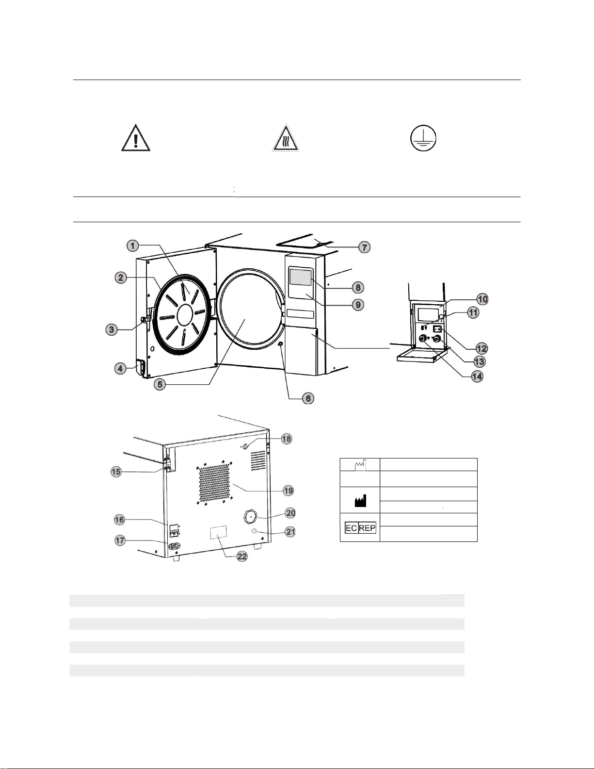
Sterilizer views
1. Door 9.
Control panel
2. Door seal ring
10. Printer
3. Door lock
11. USB
4. Door handle
12. Main switch
5. Chamber
13. Distilled water outlet
6. Door switch
Distilled water inlet*
7. Distilled water tank
14. Used
8. LCD
15. Safety valve
*Models equipped with external water
filling function.
pay close attention to the alert symbols below which can be found on the
sterilizer and throughout this manual.
Hot surface
Ground connection
sterilizer
Control panel
16. Circuit breaker
10. Printer
17. Power socket
11. USB
port
18. Used water tank vent
12. Main switch
19. Condenser vent
13. Distilled water outlet
/ 20. Bacteriological
filter
Distilled water inlet*
21. Distilled water drain*
14. Used
water tank outlet 22. Rating plate
15. Safety valve
filling function.
Date of
manufacture
SN
Manufacture number
Manufacturer Name
Manufacturer Address
EC-
Representative Name
EC-
Representative Address
5
pay close attention to the alert symbols below which can be found on the
Ground connection
18. Used water tank vent
filter
21. Distilled water drain*
manufacture
Manufacture number
Manufacturer Name
Manufacturer Address
Representative Name
Representative Address

6
Control panel
Technical Specifications
Model
Chamber (m, diameter/depth)(inches)
Overall dimensions (mm,W*H*D)
Net Weight (kg)
Nominal power (VA)
Electrical supply
Sterilization temperatures
Capacity of the distilled water tank
Circuit breaker
Operation temperature
Operation relative humidity
Max. Noise level
Atmospheric pressure
Packing content
Item
Accessories
1 Instrument tray
2
Instrument tray rack
3 Draining hose
4 Door Seal
5 Tray handle
6 Door adjustment
Wrench
7
Instruction Manual
Clave B
φ247 x 450( 9.724” x 17.716”)
490 x 455 x 690
53
2000
220-230V;50/60 Hz;10A
121°C/134°C
2.5 L (Water at level Max.) Approx.
0.5 L (Water at level Min.) Approx.
F16A /400 V
5°C ~ 40°C
Max. 80%, non-condensing
<70 dB
76 kPa ~ 106 kPa
Accessories
Quantity
4
Instrument tray rack
1
2
1
1
1
Instruction Manual
1
1 Program temperature
2 Program
3 Holding time
4 Pressure
5
Distilled water / Fill it flashing.
Filling the tank
Bad water quality
6 Used water tank full
/ Drain if flashing
7 Printer status
8
Door open
Door closed
Door blocked
9 Time
10
Current internal temperature
11 Up button
12 Down button
13 Enter button
14 Menu button
Dis tilled water / Fill it flashing.
Filling the tank
Bad water quality
/ Drain if flashing
Current internal temperature
7
3 Installation
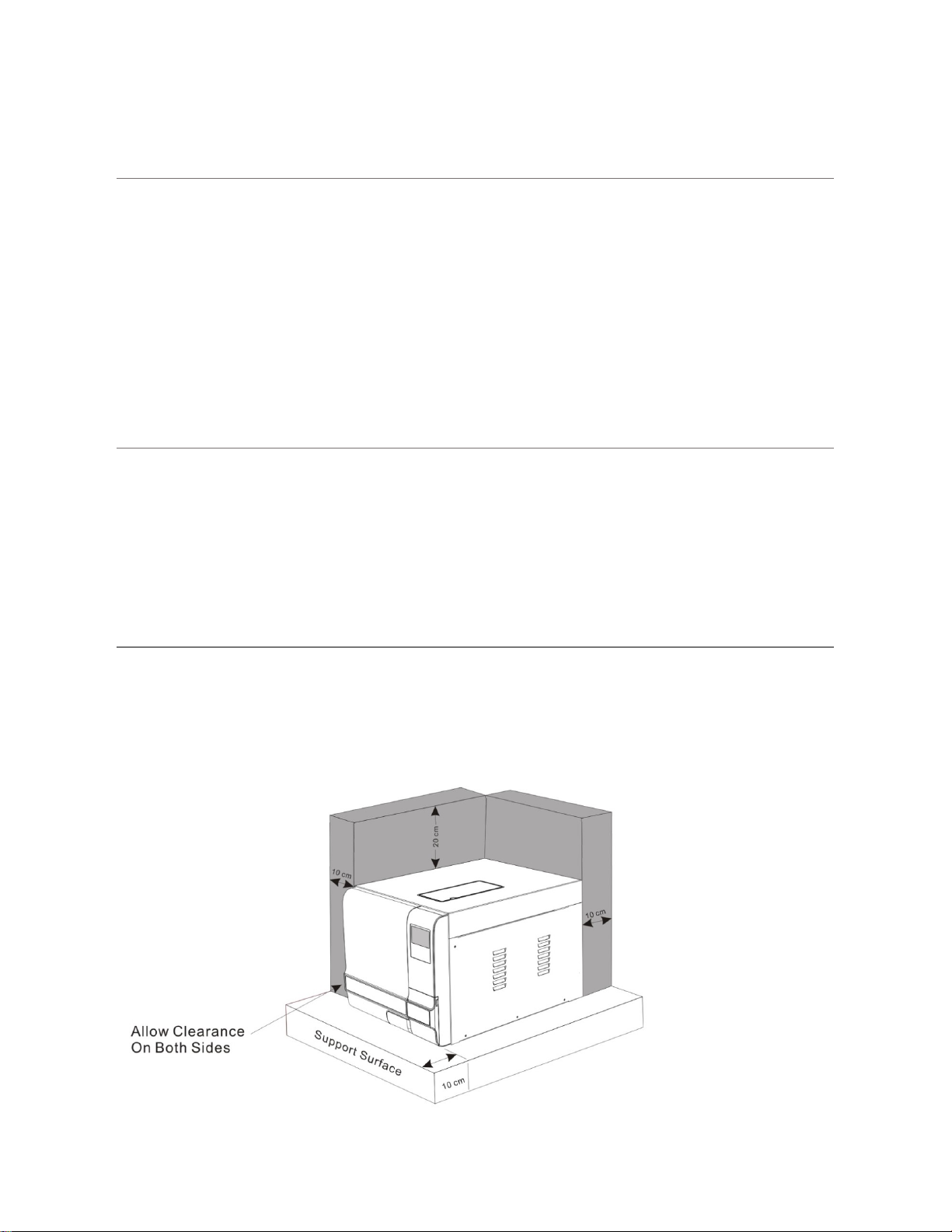
General conditions
Position the device on a solid surface with a minimum weight capacity of 60 kgs.
The sterilizer should be placed on a level worktable.
Leave at least 10 cm between the device rear part and the wall. The clearance required to
open the door is 40 cm.
Position the sterilizer at such a height as to make it possible for the operator to check the
whole sterilization chamber and carry out the normal cleaning operations.
The room where the device is installed must be sufficiently ventilated.
Do not install the device near washing basins, taps, etc. where it is likely to be splashed.
Do not lean on the door when it is opened.
Do not place trays, papers, fluid containers or other objects on the sterilizer.
Power supply connection
Check the label on the back panel of sterilizer to verify the voltage rating for the unit. Failure to
connect the sterilizer to an appropriate power supply could result in damage to the unit and electrical
shock to personnel.
Plug the power cord into a properly polarized and grounded receptacle rated for the correct voltage
and current. A dedicated circuit that is only used for the sterilizer is recommended. Never connect
the device plug to adapters of any type.
Location requirements and dimensions (mm)
To ensure proper air circulation, and to allow access to the reservoir fill port and drain coupling,
adhere to the minimum clearance requirements listed below.

8
4 Setup
Connect the power cord to an outlet of the appropriate voltage. Open the door to remove all of the
inner contents for unpacking. Turn on the main power switch on the right side. After switching on,
the machine turns on the LCD and shows the door position, water level, working program, date, time,
etc.
Fill the distilled water tank
Manual water filling
When the level of distilled water reaches a minimum level, the distilled water tank icon will flash
and beep three times.
Press the button on the tank lid and open it to the maximum position. Fill it carefully with distilled
water. If the water level exceeds the maximum level, an alarm will sound, and the distilled water
tank icon will blink.
Drain the used water tank
Attach the drain hose on the drain port connector located inside the service
door, on the left.
Attention: The capacity of the used water tank is approximately 1.5 liters.
Preparation of materials for sterilization
For the most effective sterilization and to preserve the sample, please follow below:
Clean instruments immediately after use.
Clean the instruments with an ultrasonic cleaner.
Residual chemicals left over after the cleaning and disinfecting process may damage and
corrode parts of the sterilizer. Always rinse off the instruments using distilled water.
Follow instrument manufacturer’s guidelines and recommendations for handling and cleaning
instruments prior to sterilization.
Check the manufacturer’s instructions as to proper procedure for sterilizing each item.
Arrange the samples of different materials on different trays or with at least 3cm of space
between them.
Clean and dry instruments thoroughly before placing them into a tray.
Always insert a sterilization paper or cloth between the tray and sample to avoid direct
contact.
Arrange the containers (glasses, cups, test-tubes, etc.) on one side or inverted position,
avoiding possible water pooling.
Don’t stack the trays one above the other or put them in direct contact with the walls of the
sterilization chamber.
Always use the instrument tray handle.
Wrap the samples one by one or, if more tools have to be put in the same bag, verify that
these are made of the same material.
Don’t use metallic clips, pins or similar items, as this jeopardizes the maintenance of the
sterilizer.
Don’t overload the trays over the stated limit (see appendix 2).

9
Basic Set
From the main menu, select "Basic Set”.
The “Basic Set” menu permits to set the following options:
*Date *Time *Language
Select the “Basic Set” from the main menu by pressing button.
Select the item by pressing button. The unit you selected will be highlighted.
Adjust the value by pressing buttons. Press button to select the next item.
Press button to save and exit.
Abbreviation of language options
Note: The Counter (cycle number) cannot be changed by the operator.
About device
Select “About device” from the main menu then press button.
Press button to exit.
Advance Set
The “Setup” menu permits setting the following options:
*Parameter *Unit *Preheat *Expiry date (labels) *Water quality (sensor) (optional)
and seeing the information of the: *Last error
Select “Setup” from the main menu by pressing button.
Input the password digit to digit by pressing and button to go next.
Password: 1111
CHN Chinese ENG English DEU German ESP Spanish
PL Polish FR French HUN Hungary ROM Romanian
NL Dutch LTU Lithuanian LAT Latvian CZE Czech
ITA Italian RUS Russian PT Portuguese HR Croatian
Program
Basic Set
Report
Label
Date: 11-07-2019
Time: 12:05:35
Language: ENG
Counter: 00000
Parameter
Unit
Preheat
Expiry date
Water quality
Last error
About device
Password
1111
Device Info.
3BB12B 11111110
V2.9.0.1—00
SN: A09999B12
Basic Set
Report
Label
My device
10
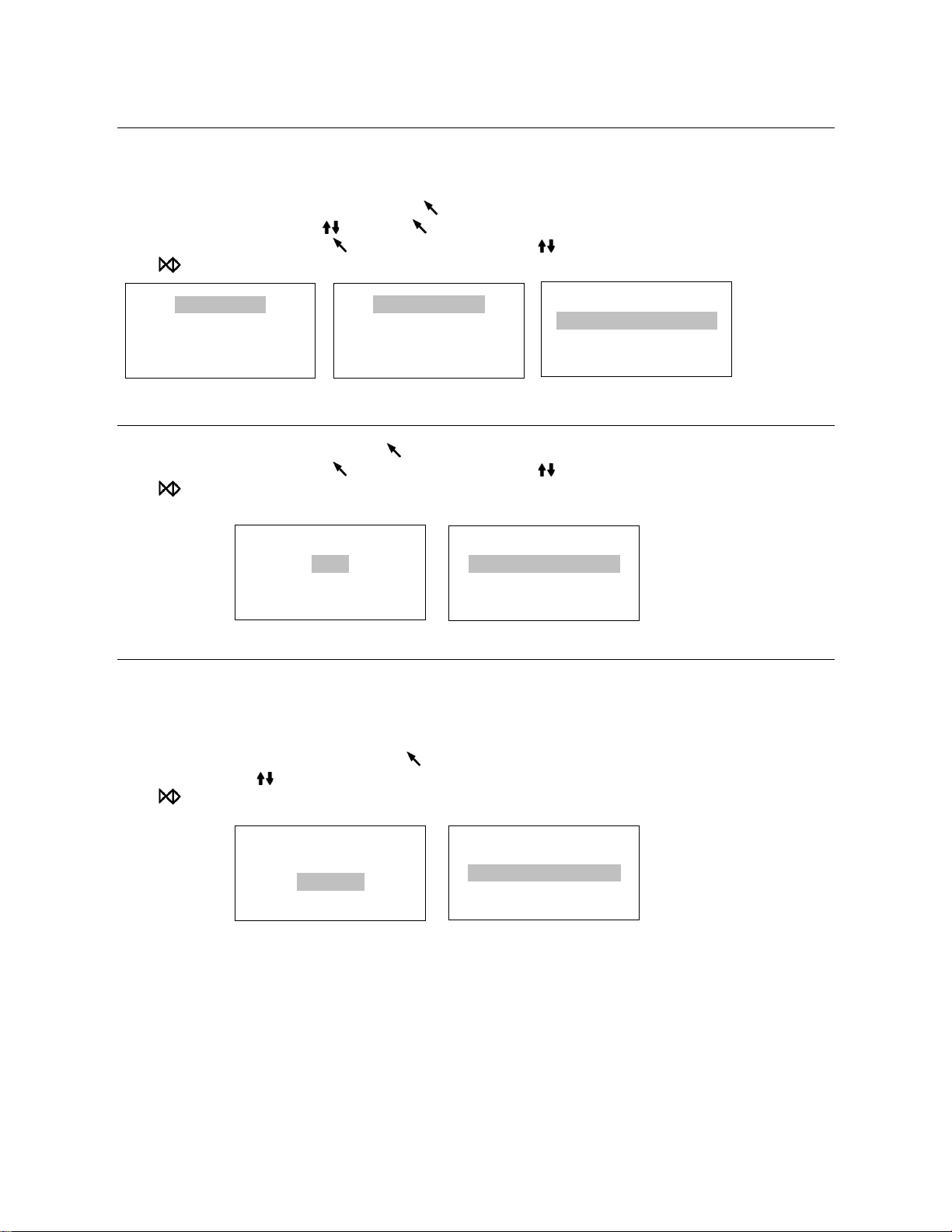
Parameter
The “Parameter” menu permits setting the following options:
*Holding time *Dry time
Select “Parameter” from the menu by pressing button.
Select the program by pressing then press button.
Select the parameter by pressing button. Adjust it by pressing .
Press button to save and exit.
Unit
Select “Unit” from the menu by pressing button.
Select the parameter by pressing button. Adjust it by pressing .
Press button to save and exit.
Preheat
When this mode is activated, the chamber and steam generator start to warm until it reaches the minimum
temperature to begin a sterilization cycle. This helps to reduce the total cycle time and improve the drying
efficiency. The “Preheat” mode will be deactivated after one hour of inactivity.
Select “Preheat” from the menu by pressing button.
Adjust it by pressing .
Press button to save and exit.
Parameter
Unit
Preheat
Expiry date
Solid (121°C)
Solid (132°C)
Wrapped (121°C)
Wrapped (134°C)
Parameter
Unit
Preheat
Expiry date
Pressure: kPa
Temperature: °C
Parameter
Unit
Preheat
Expiry date
Preheat: off
Holding time: 20.0
Dry time: 03.5

11
Expiry date (Optional)
To modify the expiration date of the labels, select “Expiry date” from the menu by pressing button.
Adjust it by pressing .
Press button to save and exit.
Water Quality (optional)
If your sterilizer is equipped with a water quality sensor and you want to deactivate it,
select “Water quality” from the menu by pressing button.
Adjust it by pressing .
Press button to save and exit.
Last Error
In order to help the technical assistance process, the most relevant information corresponding to
the last error can be displayed on the screen.
Select “Last error” from the menu by pressing button.
Press button to exit.
5 Operation
Prerequisites
Switch On.
Check the status of the icons in the screen, . (Refer to point 2. Description of the
sterilizer)
Parameter
Unit
Preheat
Expiry date
Month: 03
Unit
Preheat
Expiry date
Water quality
W. quality: OFF
Preheat
Expiry date
Water quality
Last Error
Last error: E20
13- 07 - 201 9 1 7 :0 0
PC: 01 ST : 00 C N: 0 0 04 2
P r e s s u re: 1 00 k P a
T 1: 07 0. 8 ° C T3 :0 4 0. 0° C
T 2: 0 3 3 .7 °C T4 : 24 4. 0° C
Initialize…
P : 07 k Pa T: 2 8 . 1 °
Wrapped
134 ° C/3 . 5 M i n
16- 0 7 - 2 01 9
P : 0. 0 k Pa T: 28 . 2 °C
10 : 4 5 : 05

12
Load
Open the door then placed the trays inside the chamber by the tray handle.
After the instruments are loaded, you may close the door.
Select the program
Enter to the main menu by pressing button, Select “Program”. Select the program by pressing
then press to confirm program, in the screen will appear the information of selected program as
the temperature and sterilization time (holding time), also the date, time, current pressure and
current temperature.
Start the sterilization program
Press to start the cycle. The stage, conditions and the status of the cycle will appear on the display. The
sterilizers will perform the program automatically. (see appendix 2).
End of the cycle
Once the cycle is completed, “End” will appear at the end of the graphic. The printer will print out and the
digital report is saved in the USB memory if these are connected.
Caution: Always use the tray handle to load or unload the tray into the sterilizer. Failure to do so can
result in burns.
Program
Basic Set
Report
Label
Solid (121°C)
Solid (134°C)
Wrapped (121°C)
Wrapped (134°C)
Wrapped
134 ° C/3 . 5 M i n
16- 0 7 - 2 01 9
P: 0 .0 k Pa T: 28 . 2 °C
10 : 4 5 : 0 5
1 3 4 ° C
W ra p p ed
P: 0 .0 k P a T: 2 8 . 2 °C
0 0 : 0 0: 0 5
1 3 4 ° C
W ra p p e d
P: - 0 . 2 kPa T: 8 7 . 2° C
0 0 : 0 0: 1 7
1 3 4 ° C
Wr ap p e d E N D
P: - 0. 2 k Pa T: 87.2° C
0 0 : 0 0 :1 7
13
Manual interruption of the cycle
To interrupt a cycle prematurely, hold for 3 seconds.
If the cycle is manually interrupted after it reaches the drying phase, the items inside the sterilizer may be
considered sterile and considering that the cycle has been interrupted during the drying phase the materials
and instruments inside the chamber may be wet.
Note: If the cycle is manually interrupted before it reaches the drying phase, the items inside the sterilizer
must be considered not sterile. N20 will appear on the screen. (see Error code description).
Caution: Depending on the phase of the cycle, steam and water can escape from the sterilization
chamber when you open the door.
Test Programs
Helix test
Put the Helix test device into the chamber, then, close the door.
Select “Program” from the main menu by pressing then to enter in the menu. Select “Helix
test”. The screen will show the information for temperature and sterilization time (holding time),
also the date, time, current pressure and current temperature.
Press to start the cycle. The stage, conditions and the status of the cycle will appear on the display. The
sterilizer will run the program automatically. (see appendix 2).
After finishing the cycle, you may check the indicator and evaluate the result according to the instructions
from the test manufacturer.
B&D Test
Put the B&D test package into the chamber, then close the door.
Select “Program” from the main menu by pressing then to enter in the menu. Select B&D
test. The screen will show the information for the temperature and sterilization time (holding time),
also the date, time, current pressure and current temperature.
Press to start the cycle. The stage, conditions and the status of the cycle will appear on the display. The
sterilizer will run the program automatically. (see appendix 2).
After the cycle is finished, you may check the indicator and evaluate the result according to the instructions
from the test manufacturer.
Vacuum Test
Select “Program” from the main menu by pressing then to enter the menu. Select “Vacuum
test”.
After closing the door, press to start the cycle. The stage, conditions and the status of the cycle will
appear on the display. The sterilizer will run the program automatically. (see appendix 2).
In compliance with EN 13060, the test requires that the air leakage rate be less than or equal to 0.13 kPa/min.
during 10 minutes. If the leakage rate is not greater 0.13, it will show Success.

14
If the temperature difference between the maximum temperature and the minimum is more than 3°C, it will
show void. That means the result of the test is a fail. You will need to run the vacuum test again after the
chamber has cooled down.
Data
The internal memory will store the information of the last 9999 cycles.
USB Flash memory (Optional)
A USB drive can be used as a method of storing a report of the cycle. To do so, insert the USB drive into the
slot located on the service door of the sterilizer.
The information will automatically output directly to the USB drive after the cycle has completed. The name
of the file is determined by the serial number of the machine and the cycle number.
For example:
The serial number is E00001. The cycle number is 0012.
The file name in the USB stick is 01001200.txt.
The first two numbers represent machine number.
The middle four numbers represent cycle number.
The last two numbers represent error code.
E.g. 00:no error; 01: error E01
Printer (Optional)
If installed, you can see the icon in the screen stop flashing.
At the end of each cycle the printer will print out a report of the cycle.
Note: If there is no paper inside the printer, the icon will flash.
Report
Internal Memory
In this menu you can get the information of all the cycles stored in the internal memory of the sterilizer.
Select “Report” from the main menu and press button, you will see the list of records.
Select the record by pressing button.
Press button to print and save the report.
Press button to exit.
Program
Basic Set
Report
Label
00012
00011
00010
00009
15
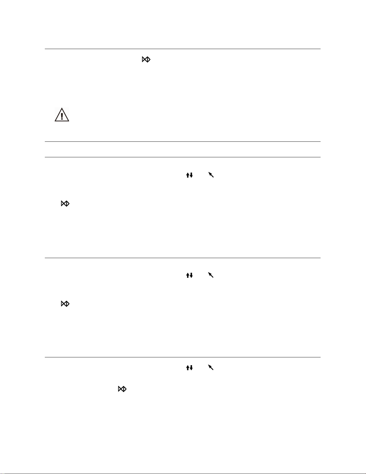
Sample of a printer report
When reading the printed data records, refer to the diagram below:
================================
Program: WRAPPED
Temperature: 134C
Pressure: 206.0 kPa
Drying Time: 08Min
Holding Time: 4.0Min
--------------------------------
Time Temp. Pressure
Start 12:28:17 089.0C
T1: 12:31:32 087.1C -075.0kPa
T2: 12:33:43 110.2C 052.0kPa
T3: 12:36:37 088.9C-075.0kPa
T4: 12:39:20 114.7C 053.7kPa
T5: 12:43:37 087.9C-075.0kPa
T6: 12:50:40 134.8C 206.0kPa
TS: 134.7C 209.5kPa
Max. Temperature:135.2C
Min. Temperature:134.3C
Max. Pressure:214.0kPa
Min. Pressure:204.9kPa
T7: 12:54:39 134.4C211.4kPa
T8: 12:57:36 102.1C -060.0kPa
T9: 12:59:54 098.2C-060.0kPa
End 13:04:07 102.4C
--------------------------------
Cycle No.: 00017
Ster. Value: Success
Date: 2017-06-07
SN:E54723
Operator:
v 2B00V2.5
================================
=======================
Program:Vacuum test
Tp:1℃
P1:-75.0kPa
P2:-74.0kPa
rate of pressure rise:0.10
Start Time:08:22
End Time:09:01
Date:2017-07-19
Test Value:Success
SN:E00001
Operator:
========================
16
Print labels
Select “Label” from the main menu and press button to enter the menu.
Select the cycle number by pressing button. Choose the labels quantity by pressing then
press button to print.
Press button to exit.
6 Maintenance
To ensure proper operation and maximum steam sterilizer life, carefully follow all recommendations for
periodic maintenance. One of the most important steps you can take to prevent problems with your sterilizer is
to use only distilled water.
Frequency Number of cycles Maintenance operation
Daily
Clean the external surface
Drain used water tank
Clean the door seal
Weekly 25 Clean the chamber, trays and rack
Clean distilled water tank (drain tank)
Monthly 100 Clean the filter inside the chamber and in the distilled
water tank
Every 6 months 500 Replace the bacteriological filter
Every year 1000 Replace door seal, tubing, filters, check valves
Clean the distilled water tank
Unplug the power cable, or drop the circuit breaker at the back of the unit.
Drain the tank completely using the drain connector at the front of the sterilizer and leave it connected to a
tube in an open position.
Clean the internal surface with a soft sponge and a small soft brush for the areas difficult to reach using
distilled water.
Remove the filter and clean it with a small soft brush and mild soap, rinse it with distilled water, and put it
back in to the position.
Replacement of the bacteriological filter.
The bacteriological filter is in the back of the sterilizer. Unscrew the filter by hand counter-clockwise.
Place the new bacteriological filter. Screw the new filter by hand clockwise.
Note: Do not operate sterilizer without filters in place.
Clean chamber, door seal ring, trays, and tray rack.
Remove the trays and tray rack from the chamber. Clean the trays, rack and the inside of the chamber with
mild soap.
Rinse the trays, rack and inside of the chamber with a smooth cloth and distilled water.
Examine door seal for possible damage. Clean door seal and mating surfaces with a damp cloth.
Note: Do not use bleaching agents or any abrasive materials or substances in the chamber. Failure to comply
may cause damage to the chamber and/or other components.
Caution: To prevent burns, let the unit cool before cleaning gaskets and touching the surface.
Program
Basic Set
Report
Label
00012
00011
00010
00009
QT: 01

17
Door adjustment
Under normal circumstances, the chamber door does not require adjustments.
However, if the seal fails (resulting in steam leaking from the front of the chamber),
you may need to adjust it.
Open the door.
Insert the spanner tool in the gap beneath the plastic cover. Use the spanner to grip
the adjusting nut. Turn the nut counter clockwise as the figure below. This will tighten the sealing plate.
Turn the nut until the sealing plate is tight. If the door knob is too tight, you may also turn
the nut clockwise to loosen it.
Caution: Never adjust the chamber door while the door is closed.
Replacement of the door seal ring
Open the chamber door. Remove the door seal ring carefully by hand.
Clean the door seal ring carefully with a smooth cloth with distilled water.
Moisten the new seal with distilled water.
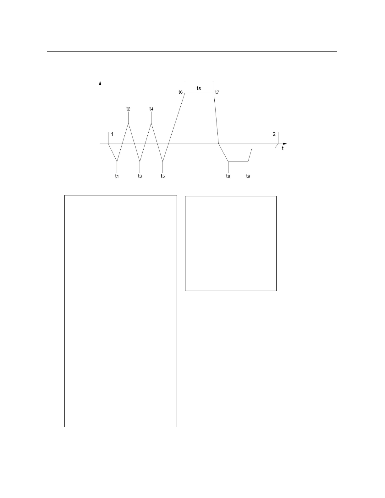
Insert the new seal and tap in sequence as follows:
Press in the top and bottom of
the door seal.
Press in the left and right
sides of the door seal.
Press the remaining sections
of the seal.
Caution: Please ensure the chamber and the door are cold prior to replacing the seal ring.
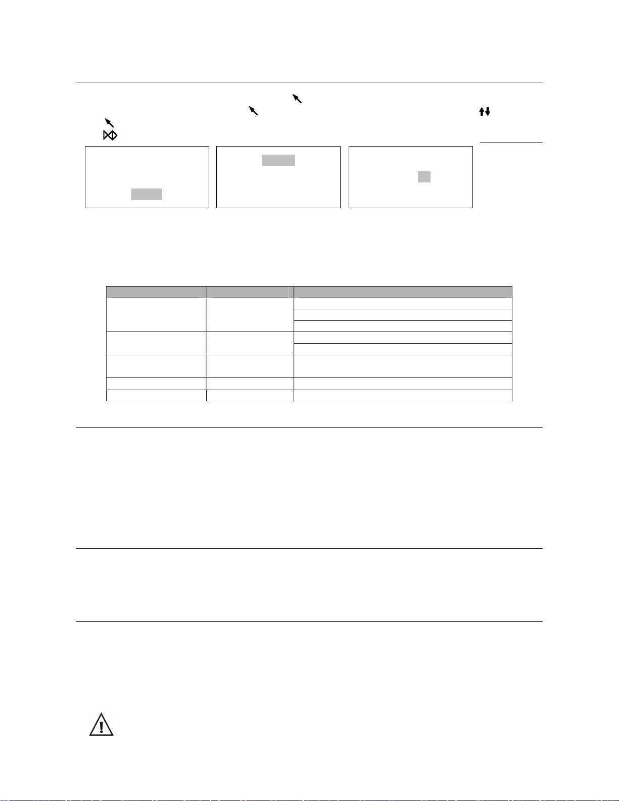
The drain valves
1. Press the included hose
onto the drain valve firmly.
2. Pull the drain valve
outward to drain the tank.
3. Push the drain valve back
after draining the tank.

18
7 Troubleshooting
Code Description Proposed solution
E1 Steam generator temperature
sensor error.
Power off & run a new cycle
Contact your supplier if error persists.
E2 Inner temperature sensor error. Power off & run a new cycle
Contact your supplier if error persists.
E3 Temperature sensor of the
chamber wall error.
Carefully ensure that the chamber wall is
heated and contact your supplier.
E5 Fail to release the pressure. Power off & run a new cycle
Contact your supplier if error persists.
E6 Door lock problem during the
cycle.
Make sure you had closed the door properly.
Check the door switch.
E7 Error between temperature and
pressure correlation.
Power off & run a new cycle
Contact your supplier if error persists.
E8
Error between temperature and
pressure correlation.
Power off & run a new cycle
Contact your supplier if error persists.
E9 Failure to hold temperature.
Ensure the distilled tank isn't empty. Check
the inner temperature sensor. Check
somewhere for leaking.
E10 The door locking system
doesn’t work.
The electromagnet locking system doesn’t
work.
The locking system switch doesn’t work.
E11 Failure to preheat the steam
generator.
Power off & run a new cycle
Contact your supplier if error persists.
E12 Failure to preheat the chamber. Power off & run a new cycle
Contact your supplier if error persists.
E13 Vacuum failed. Power off & run a new cycle
Contact your supplier if error persists.
E15 Inner temperature sensor error
#2*
Power off & run a new cycle
Contact your supplier if error persists.
E16 Pressure error
Replace the air filter
Power off & run a new cycle
Contact your supplier if error persists.
N20 Program manually interrupted Reset the error from main screen.
E22 Vacuum test failure Leaking somewhere. Check the door seal.
Or contact your supplier if error persists.
N23 Result of vacuum test is void
The temperature of the chamber is high.
Try again after the chamber has cooled down.
E24 It takes too long time to enter
the next status.
Check for leaks.
Or contact your supplier if error persists.
N27 The vacuum test fails. Switch off. Then switch on after the chamber
cools down and try again.
E28 The pressure is too high.
Power off and contact your supplier if error
persists.
E30 Vacuum failed. Power off & run a new cycle
Contact your supplier if error persists.
E31 Inner temperature sensor error
#2*
Power off & run a new cycle
Contact your supplier if error persists.

19
8 Transportation and storage
Switch off the sterilizer before transportation or storage.
Pull out the plug. Let the machine cool down.
Drain the distilled water tank and the used water tank.
Conditions for transport and storage
Temperature: -20°C ~ +50°C
Relative humidity: ≤ 85%
Atmospheric pressure: 50kPa~ 106kPa.
9 Safety devices
1. Main breaker: Protection of the instrument against possible failures of the heating elements.
Action: Interruption of the electric power supply.
2. Thermal cutouts on the main transformer winding: protection against possible short circuit and main
transformer primary winding overheating
Action: Temporary interruption of winding.
3. Safety valve: Protection against possible sterilization chamber over-pressure.
Action: Release of steam and restoration of the pressure to a safe level.
4. Safety micro-switch for the door status: Comparison for the correct closing position of the door.
Action: Signal of the wrong position of the door.
5. Thermostat on chamber heating elements: Protection for possible overheating of the chamber heating
elements.
Action: Interruption of the power supply of the chamber elements.
6. Thermostat on steam generator heating elements: Protection for possible overheating of the steam generator
heating elements.
Action: Interruption of the power supply of the steam generator elements.
7. Door safety lock: Protection against accidental opening of the door.
Action: Prevents the accidental opening of the door during the cycle.
8. Self-leveling hydraulic system: Hydraulic system for the natural pressure leveling in case of manual cycle
interruption, alarm or blackout.
Action: Automatic restoration of the atmospheric pressure inside the chamber. (valve opens to release internal
pressure)

20
Appendix 1
Water properties / Characteristics
Description Feed water Condensate
Evaporate residue ≤ 10mg/ I ≤ 1.0mg/kg
Silicon oxide sio2 ≤ 1mg/ I ≤ 1.0mg/kg
Iron ≤ 0.2mg/ I ≤ 0.1mg/kg
Cadmium ≤ 0.005mg/ I ≤ 0.05mg/kg
Lead ≤ 0.05mg/ I ≤ 0.1mg/kg
Rest of heavy metals ≤ 0.1mg/ I ≤ 0.1mg/kg
Chloride ≤ 2mg/ I ≤ 0.1mg/kg
Phosphates ≤ 0.5 mg/ I ≤ 0.1mg/kg
Conductivity ≤ 15μs /cm ≤ 3 μs /cm
PH Value 5 – 7.5 5 - 7
Appearance Colorless, clean Colorless, clean
Hardness 0.02 mmol/ I 0.02 mmol/ I
Table of contents
Other Flight Dental Systems Laboratory Equipment manuals

Popular Laboratory Equipment manuals by other brands


Hamamatsu
Hamamatsu Energetiq LDTLS TLS-EQ-9 Operation manual

MicroDigial
MicroDigial Nabi user manual

NuAire
NuAire BR Series Operation & maintenance manual

Heidolph
Heidolph Hei-TORQUE Expert operating instructions

Thermo Scientific
Thermo Scientific Sorvall X Pro Series Instructions for use

Thermo Scientific
Thermo Scientific FB1300 Installation and operation manual


