manuals.online logo
Brands
  1. Home
  2. •
  3. Brands
  4. •
  5. Waters Network Systems
  6. •
  7. Switch
  8. •
  9. Waters Network Systems EN-FUTP-8 User manual

Waters Network Systems EN-FUTP-8 User manual

MODEL EN-FUTP-8
10 BASE-T ETHERNET HUB
INSTALLATION AND USERS MANUAL
CORPORATE HEADQUARTERS MANUFACTURING/CUSTOMER SERVICE
13705 26th Avenue N., Suite 102 2411 Seventh Street NW
Minneapolis, MN 55441 Rochester, MN 55901
Phone: (800) 441-5319 Phone (800) 328-2275
Fax: (763) 509-7450 Fax: (507) 252-3734
E-mail: netinfo@wtrs.com www.watersnet.com E-mail: netinfo@wtrs.com
UNPACKING AND VISUAL INSPECTION
While unpacking the Waters’ EN-FUTP-8 hub, inspect carefully to determine whether damage has occurred
during shipping. If you notice any damage, please contact your carrier and your Waters Network Systems’
Customer Service Representative.
CONFIGURING THE NETWORK
The hub gives you flexibility in configuring. Use the following guidelines to assist in planning your configuration.
The following cable types may be used when connecting the hub.
10 Base-T: Shielded or unshielded twisted pair cable, which meets IEEE 802.3 10 Base-T standards
category 3, 4, or 5.
Fiber: The fiber port accepts ST type connectors using 50/100, 62.5/125, or 100/150 multi-mode fiber
cable.
Single Hub: The eight ports may be used for connection to workstations or servers. The maximum cable
length between the workstation and the hub recommended by the IEEE 802.3 standard is 100
meters for 10 Base-T and 2 km for fiber.
Multiple: Multiple hubs may be connected through the backbone using the fiber ports or connecting to
another Ethernet device via the fiber connection. The same connections may be made using
the AUI or 10 Base-T ports.
INSTALLING THE HUB
Verify the following items were included with the hub:
 The Network Access Unit
 (1) External Power Supply
 (1) Accessory Kit
 Installation Manual
If any of the above items were not received or if the unit does not function properly, please contact Waters
Network Systems at 800-328-2275.
Mounting
A single hub can be either wall or desktop mounted. There are mounting holes located on the back of the hub
for wall mounting and rubber feet enclosed for desktop applications.
Installing
Plug power supply into power port of the hub and into an AC power outlet. The “PWR” LED light should be on.
As required, attach the network cables to station ports and/or to the fiber port.
OPERATION
Once the hub is installed, it automatically partitions ports out of the network if excessive collisions are detected.
Stations are automatically reconnected when the collision condition is removed.
The top panel indicators on the hub can be used to determine its performance, which simplifies troubleshooting.
TROUBLESHOOTING
If persistent symptoms occur on the network, the following steps may help in determining if the hub is not
working properly.
 Reset the hub by unplugging and reconnecting the power supply.
 Attach the workstation to a different port to determine if the problem stays with the hub port or if it follows the
workstation. If the problem does not follow the workstation, the hub may have a bad port.
 Make sure the IEEE 802.3 cable length, repeater limits, and other specifications are not violated.
WATERS NETWORK SYSTEMS EN-FUTP-8 Manual Page 2
 Make sure all connections are secure.
 Make sure the network is properly configured.
 Ensure that the TX and RX fiber cables are not reversed or that when connecting two standard ports or two
crossover ports, a crossover cable is used.
ELECTRICAL SPECIFICATIONS:
10 Base-T Interface 8 Position modular jack (RJ45)
10 Base-T Cable Length 100 meters maximum
Fiber Interface Two ST type fiber connectors
Fiber Cable Length 2km maximum
AUI Interface DB-15 receptacle connector
AUI Cable Length 50 meters maximum
Power Requirements 12 Vdc. 1 Amp
FEDERAL COMMUNICATIONS COMMISSION (FCC) STATEMENT
This equipment generates, uses, and can radiate radio frequency interference energy and if not installed and
used in accordance with the instruction manual, may cause interference to radio communications. It has been
tested and found to comply with the limits for a Class A computing device pursuant to Subpart J of Part 15 of
FCC rules, which are designed to provide reasonable protection against such interference when operated in a
commercial environment. Operation of this equipment in a residential area is likely to cause interference. In this
case the user, at his own expense, will be required to take whatever measures may be required to correct the
interference.
HUB FEATURES
Station Ports: Each hub provides eight 10 Base-T station attachment ports using shielded RJ45
modular jacks. The station ports will accept either STP or UTP 100 OHM copper cable.
The maximum cable length is 100 meters. These ports have automatic polarity
detection and correction capability.
Fiber Ports: The EN-FUTP-8 HUB provides a single fiber optic port using two ST type connectors.
This port is used to connect to other Ethernet devices such as other repeater hubs or
workstations. The fiber media also increases the maximum cable length to 2km.
LED Indicators: Each hub contains 20 LED indicators. Each port has two associated indicators and
there are two for each hub.
STATUS LED’S
Indicator Relates to Color Function
PWR Hub Green Lights to indicate power is applied to the hub.
COL Hub Yellow A collision has been detected. Remains lit until collision ceases.
LNK/TX Port Green Steady when receiving link pulses. Blinks for transmitted data.
POL/RX Port Yellow Steady for reverse polarity. Blinks for received data.
TX Fiber/AUI Green Steady for receive jabber. Blinks for transmitted data.
RX Fiber/AUI Yellow Steady for received collision. Blinks for received data.
WATERS NETWORK SYSTEMS EN-FUTP-8 Manual Page 3
WATERS NETWORK SYSTEMS EN-FUTP-8 Manual Page 4
SAFETY PRECAUTIONS
Waters’ products are designed to allow safe operation under normal conditions. Precautions that should be
taken to avoid improper or unsafe installation of the hub include the following:
To avoid a shock hazard:
 Do not connect or disconnect any cables or perform installation, maintenance, or reconfiguration of this
product during an electrical storm.
 The power supply must be connected to a properly wired and grounded receptacle. Any attached
equipment must also be connected to a properly wired receptacle.
 Properly stow all cables to eliminate tripping hazards.
OPERATING ENVIRONMENT
The Waters’ Network Access Unit is designed to operate in an environment whose ambient temperature ranges
from 0º to 50º C with 5% to 95% relative humidity.
WARRANTY:
All products manufactured by Waters Network Systems come with a limited lifetime warranty. Contact
Waters Network Systems for further details.

Other Waters Network Systems Switch manuals
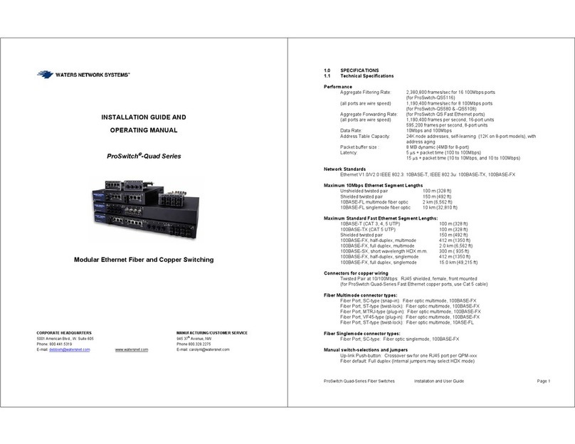
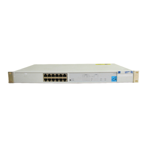
Waters Network Systems ProSwitch-Quad Series User manual

Waters Network Systems

Waters Network Systems ProSwitch-Quad Series User manual

Waters Network Systems GS1008 User manual

Waters Network Systems

Waters Network Systems GS1008 User manual

Waters Network Systems ProSwitch Lite User manual

Waters Network Systems

Waters Network Systems ProSwitch Lite User manual

Waters Network Systems ProSwitch FlexPort- 2600M User manual

Waters Network Systems

Waters Network Systems ProSwitch FlexPort- 2600M User manual

Waters Network Systems GSM 2124 User manual
Waters Network Systems

Waters Network Systems GSM 2124 User manual

Waters Network Systems ProSwitch 2800M User manual

Waters Network Systems

Waters Network Systems ProSwitch 2800M User manual

Waters Network Systems GS1016 User manual

Waters Network Systems

Waters Network Systems GS1016 User manual

Waters Network Systems MS1008-2G-4POE User manual

Waters Network Systems

Waters Network Systems MS1008-2G-4POE User manual

Waters Network Systems GSM2109-1009-8PoE User manual

Waters Network Systems

Waters Network Systems GSM2109-1009-8PoE User manual

Waters Network Systems PS-2126M-POE User manual

Waters Network Systems

Waters Network Systems PS-2126M-POE User manual

Waters Network Systems GSM2109 User manual

Waters Network Systems

Waters Network Systems GSM2109 User manual

Waters Network Systems ProSwitch FlexPort- 2600M User manual

Waters Network Systems

Waters Network Systems ProSwitch FlexPort- 2600M User manual

Waters Network Systems PSL1008-MSC User manual

Waters Network Systems

Waters Network Systems PSL1008-MSC User manual

Waters Network Systems ProSwitch-Secure 1007 User manual
Waters Network Systems

Waters Network Systems ProSwitch-Secure 1007 User manual

Waters Network Systems PSX1008-GTX User manual

Waters Network Systems

Waters Network Systems PSX1008-GTX User manual

Waters Network Systems PSX1008-TX User manual

Waters Network Systems

Waters Network Systems PSX1008-TX User manual

Waters Network Systems GSM2108 User manual

Waters Network Systems

Waters Network Systems GSM2108 User manual

Popular Switch manuals by other brands

Becker 4901 001 158 0 technical information

Becker

Becker 4901 001 158 0 technical information

Reed Instruments R2800 instruction manual

Reed Instruments

Reed Instruments R2800 instruction manual

Juniper EX8200 Series quick start guide

Juniper

Juniper EX8200 Series quick start guide

Bticino BTK4003CWI manual

Bticino

Bticino BTK4003CWI manual

WiSilica Lumos Controls Catron IV Quick Start Sheet

WiSilica

WiSilica Lumos Controls Catron IV Quick Start Sheet

Converters.TV CDPS-UH4H1HFS Operation manual

Converters.TV

Converters.TV CDPS-UH4H1HFS Operation manual

3Com Baseline 2250 Plus specification

3Com

3Com Baseline 2250 Plus specification

LevelOne POH-1250 Brochure & specs

LevelOne

LevelOne POH-1250 Brochure & specs

Opengear OM2200 Series user guide

Opengear

Opengear OM2200 Series user guide

Intermatic T101 supplementary guide

Intermatic

Intermatic T101 supplementary guide

NK TECHNOLOGIES AS3 Series instructions

NK TECHNOLOGIES

NK TECHNOLOGIES AS3 Series instructions

TP-Link TL-SF1005D installation guide

TP-Link

TP-Link TL-SF1005D installation guide

Network Technologies SERIMUX-S-x Installation and operation manual

Network Technologies

Network Technologies SERIMUX-S-x Installation and operation manual

INSTEON 2242-422 quick start guide

INSTEON

INSTEON 2242-422 quick start guide

ADTRAN NetVanta 1560-24-740W quick start

ADTRAN

ADTRAN NetVanta 1560-24-740W quick start

Panasonic WJMP204C - DATA MULTIPLEX UNIT operating instructions

Panasonic

Panasonic WJMP204C - DATA MULTIPLEX UNIT operating instructions

Vimar Eikon 20592.0 manual

Vimar

Vimar Eikon 20592.0 manual

NETGEAR FS526T - Switch Specifications

NETGEAR

NETGEAR FS526T - Switch Specifications

manuals.online logo
manuals.online logoBrands
  • About & Mission
  • Contact us
  • Privacy Policy
  • Terms and Conditions

Copyright 2025 Manuals.Online. All Rights Reserved.