HIGHGATE
Pressure Balance with Diverter Trim INSTALLATION GUIDELINES
Page 1 of 3
6.6.2012
These guidelines have been prepared for the professional contractor to aid in the installation of:
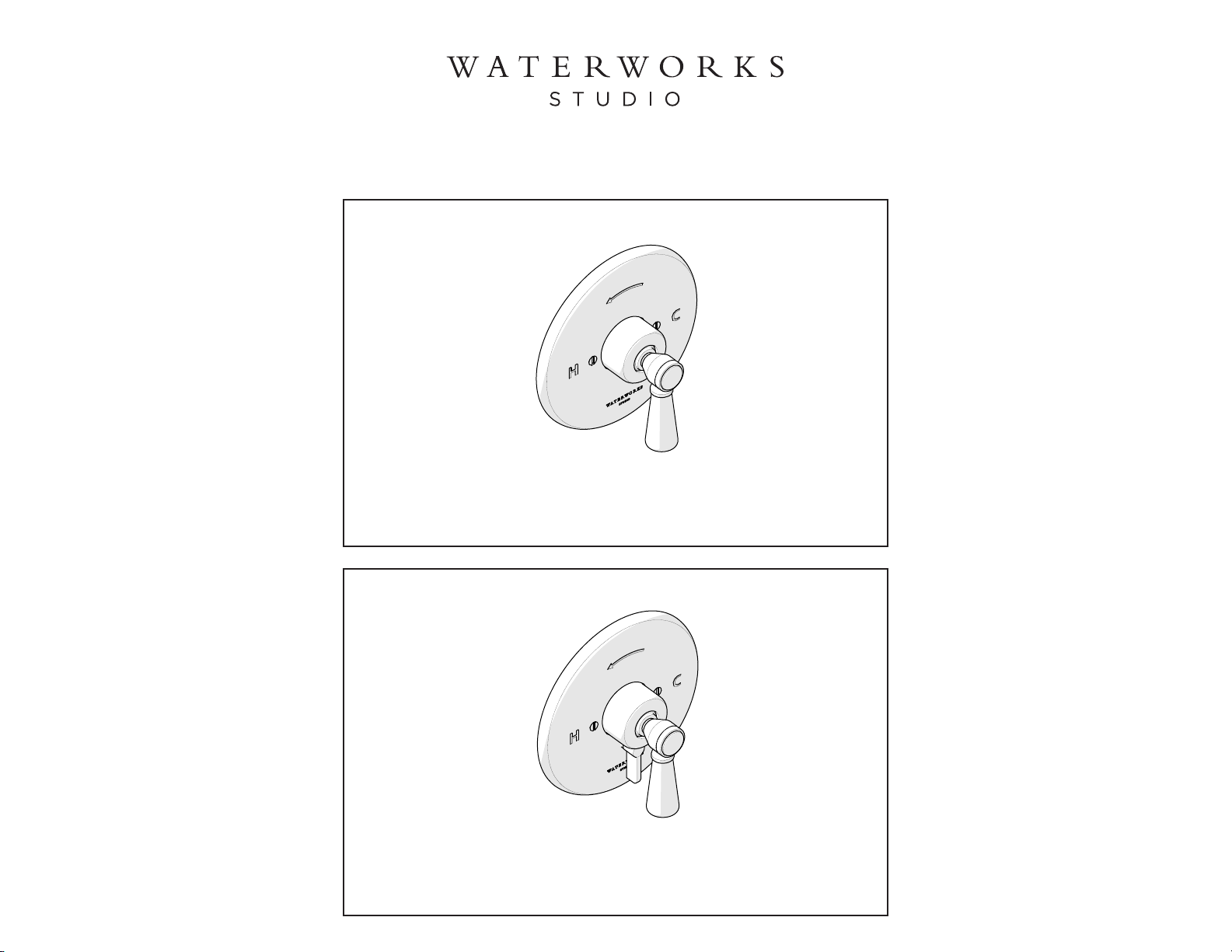
HIGHGATE PRESSURE BALANCE TRIM WITH PORCELAIN LEVER HANDLE WITH DIVERTER
(STYLE# HGPB30)
All dimensions are based on original specification and are subject to change and variation.
Please consult your Design Associate for current specifications.
White Porcelain Lever Handle
Style No. HGPB30
SPECIFICATIONS:
Rough-in Depth Minimum: 1-7/8"
Rough-in Depth Maximum: 2-7/8"
Integrated Diverter: Yes
REQUIRED PLUMBING DETAILS:
Universal Pressure Balance with Diverter Valve
STYLE # GUPB87R
CODE # GUSV87R
IMPORTANT:
¾To ensure this product is installed properly, you
must read and follow these guidelines.
¾The owner/user of this product must keep this
information for future reference.
¾This product is intended to work with the
Waterworks Universal Pressure Balance with
Diverter Valve (Style # GUPB87R). The risk of
scalding exists until the installer has properly
calibrated/adjusted the temperature setting during
final trim installation.
¾The bottom outlet of the GUPB87R is intended for
use with a tub spout only. The use of any fitting with
a restricted flow, such as a handshower, will cause
the diverter to not function properly.
¾Do not use Pex piping from the valve to the tub
spout. This will cause too much back pressure for
the valve to function properly.
¾Be sure your installation conforms to federal state,
and local codes. In the State of Massachusetts, all
installations must comply with the rules and
regulations set forth within 248 CMR.
¾This product must be installed by a professional
licensed contractor.
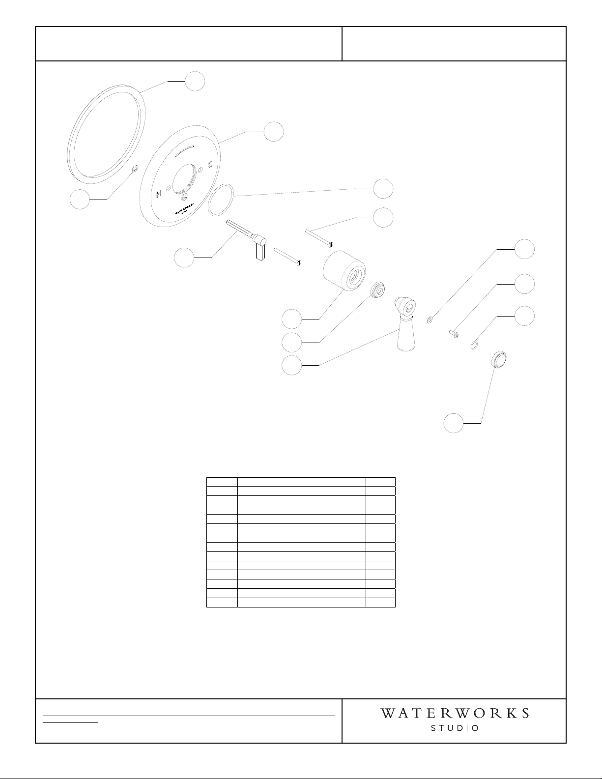
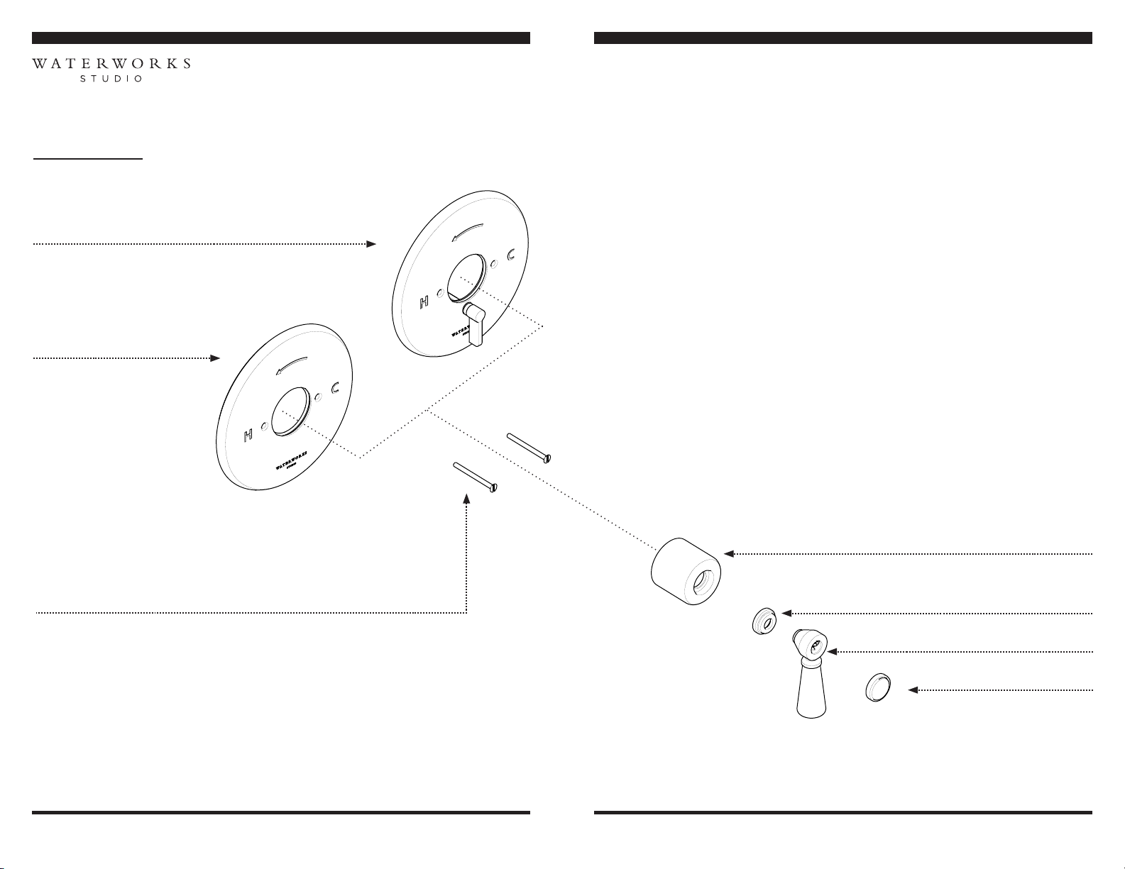
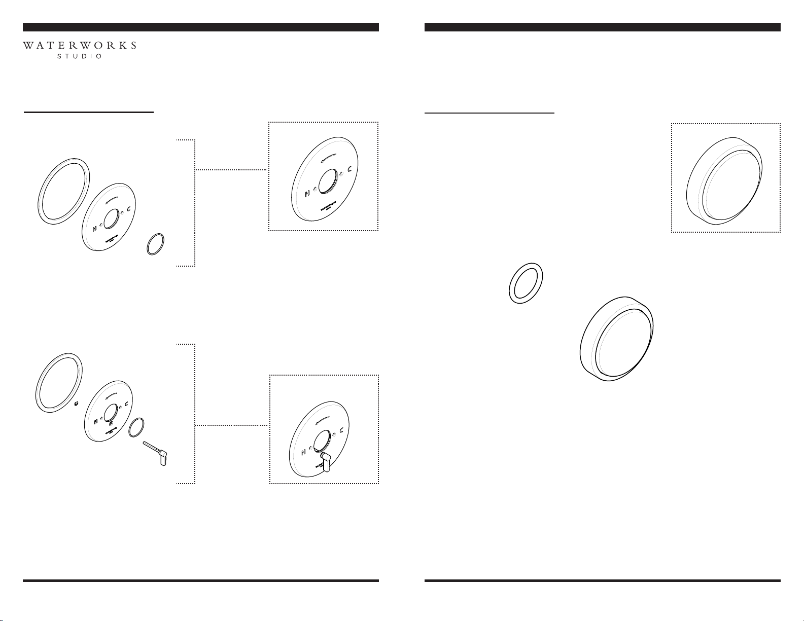
¾Refer to the specifications and assembly drawings
attached. Product is sold partially assembled but
shown fully disassembled for illustrative and service
purposes only.
¾Inspect this product to ensure you have all the parts
required for proper installation.
¾This product must be on-site prior to rough-in which
allows the installer to visualize the installation.
¾Use only a strap wrench or protected/smooth-jaw
wrench on any finished surface.
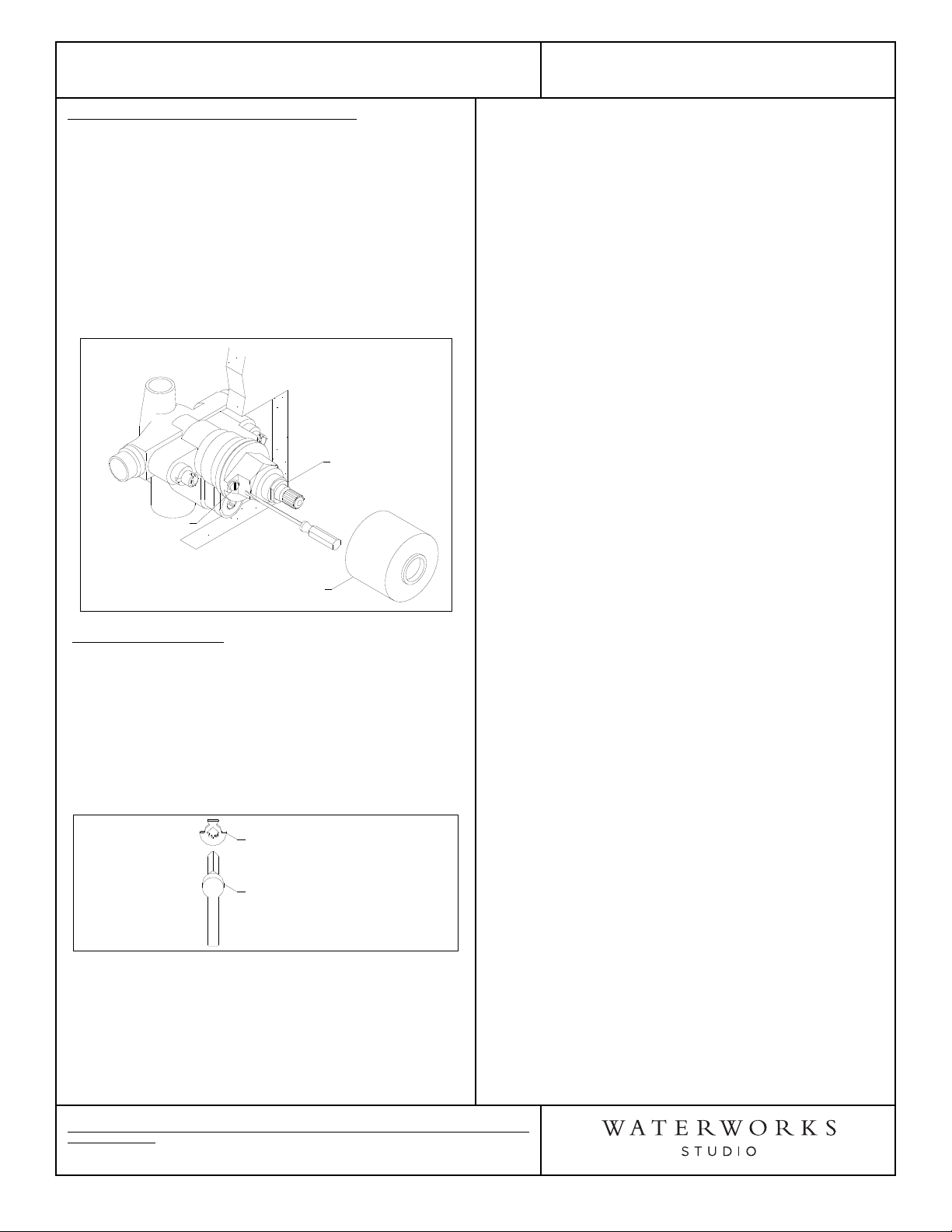
VALVE OPERATION:
1. When the finished wall is complete, turn on the hot
and cold supplies and pull off the tile guard. Valve
will not operate unless BOTH supplies are turned on.
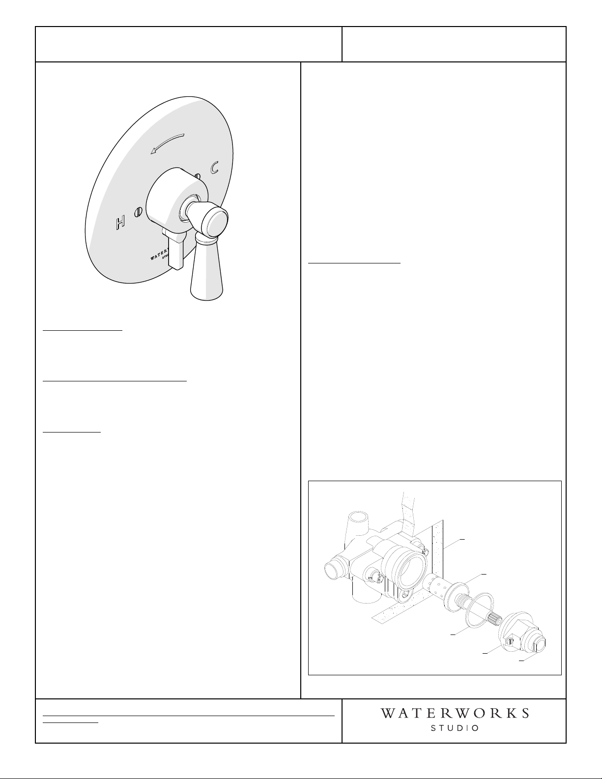
2. The lever handle (5) is for controlling the
temperature only, not volume. Place the handle on
the valve stem so it rests at 6 o'clock in the OFF
position and then turn the handle counter clockwise
through the cold, then warm and stopping at the hot
position. If additional rotational friction is required to
maintain the handle position, tighten the packing
nut. See Figure-01.
3. Allow the valve to run in the warm position for a few
minutes to completely flush the system. If system is
quite dirty, remove valve spindle to ensure proper
flushing. Refer to the Installation Guidelines for the
Pressure Balance Valve which contains a complete
parts breakdown and related information.
Figure - 01
Valve Spindle
Plastic Washer
Bonnet
Finished Wall
Packing Nut