manuals.online logo
Brands
  1. Home
  2. •
  3. Brands
  4. •
  5. Waterworks
  6. •
  7. Plumbing Product
  8. •
  9. Waterworks On Tap OTKM10 Instruction sheet

Waterworks On Tap OTKM10 Instruction sheet

STYLE No. OTKM10, OT10KM
On Tap One Hole High Profile Kitchen Faucet
with Metal Wheel, Black Ball Handle and Spray
INSTALLATION GUIDELINES
PAGE
1
OF
5
|
UPDATED ON
8.1.2018
PRODUCT SUPPORT | 800.927.2120 | WATERWORKS.COM
IMPORTANT:
To ensure this product is installed properly, you must read and
follow these guidelines.
The owner/user of this product must keep this information for
future reference.
This product must be installed by a professional licensed
contractor.
Be sure your installation conforms to federal, state, and local
codes. In the State of Massachusetts, all installations must comply
with the rules and regulations set forth within 248 CMR.
Inspect this product to ensure you have all the parts required for
proper installation. Product is sold partially assembled but shown
fully disassembled for illustrative and service purposes only.
Use only a strap wrench or protected/smooth-jaw wrench on any
finished surface.
The use of certain plumber’s putty may stain stone or tile surfaces.
If further assistance is required, please contact Product Support at
1-800-927-2120 Monday through Friday, 8am – 6pm EST.
Refer to the separate Service Parts Documents for available
replacement parts.
TECHNICAL DETAILS:
DETAIL SPECIFICATION
ADJUSTABLE VERSUS FIXED SPRAY FIXED
MAXIMUM DECK THICKNESS 1-15/16” [49mm]
FITTINGS HOLE DIAMETER 2” [51mm] - (FAUCET)
1-1/2” [38mm] - (SPRAYER)
HANDLE TURN ANGLE QUARTER TURN
INLET CONNECTION 3/8” COMPRESSION CONNECTOR HOSES ‡
RESTRICTED MAXIMUM FLOW RATE 2.2gpm [8.3L/min]
SPOUT REACH 10-1/8” [257mm]
SPOUT SWIVEL YES
SPRAY HOSE LENGTH 49” [1.2m]
SPRAY INCLUDED IN UNIT YES
WATER PRESSURE RANGE 20psi [1.5 bar] MIN
85psi [6.0 bar] MAX
WATER PRESSURE RECOMMENDED 45psi [3.0 bar]
‡UK Style No. OT10KM is supplied with 2 BSPP adapters, assembly required.
†† SPRAY can be installed on RIGHT or LEFT side of FAUCET
[MOUNTING SURFACE – TOP VIEW]
Ø2"
[51mm]
FAUCET
FITTINGS
HOLE
Ø1-1/2"
[38mm]
SPRAY
FITTINGS
HOLE
3-1/8"
[79mm]
FROM CENTER TO
FINISHED WALL/
BACKSPLASH
BACKSPLASH/
FINISHED WALL
MINIMUM
STYLE No. OTKM10, OT10KM
On Tap One Hole High Profile Kitchen Faucet
with Metal Wheel, Black Ball Handle and Spray
PAGE
2
OF
5
|
UPDATED ON
8.1.2018
PRODUCT SUPPORT | 800.927.2120
| WATERWORKS.COM
INSTALLATION GUIDELINES
1. Unthread and remove the NUT and RUBBER WASHER from the SPOUT SHANK.
NOTE: Do NOT remove the RUBBER WASHER beneath the ESCUTCHEON.
2. Thread and securely tighten the SUPPLY HOSES onto the SUPPLY TUBES installed on the
SPOUT.
NOTE: The HOSES are M10 x 3/8” COMPRESSION CONNECTOR HOSES and the SUPPLY
TUBES are marked BLUE for cold and RED for hot.
NOTE: 2 CHECK VALVES are located inside each of the ADAPTER.
3. Insert the SPOUT through the hole on the mounting surface making sure the RUBBER
WASHER provided is beneath the ESCUTCHEON and the SCREW on the SPOUT COLUMN
is aligned towards the finished wall/backsplash then slide the RUBBER WASHER and NUT
over the HOSES and TUBES. Ensure the SPOUT is properly aligned then thread and
securely tighten the NUT.
RUBBER WASHER
[DO NOT REMOVE]
ESCUTCHEON
SHANK
OUTLET TUBE
SUPPLY TUBE
[RED LABEL]
SUPPLY TUBE
[BLUE LABEL]
RUBBER WASHER
NUT
RUBBER
WASHER
ADAPTER
[3/8" x 1/2"]
CHECK
VALVE
CHECK
VALVE
RUBBER
WASHER
ADAPTER
[1/2" x M10] SUPPLY
HOSE
SUPPLY
HOSE
SUPPLY VALVE
[SOLD SEPERATELY]
SUPPLY HOSE ‡
SUPPLY HOSE ‡
SUPPLY VALVE
[SOLD SEPERATELY]
SUPPLY HOSE ‡
SUPPLY HOSE ‡
‡ UK installations only!
2 BSPP ADAPTERS, 9/16"-24 UNEF Male
x 3/8" FEMALE BSPP, for SUPPLY HOSES
are provided.
4. Connect the SUPPLY HOSES to the SUPPLY VALVES (sold separately).
NOTE: The HOSES are connected to SUPPLY TUBES that are marked BLUE for cold and
RED for hot.
NUT
RUBBER
WASHER
MOUNTING
SURFACE
RUBBER WASHER
ESCUTCHEON †
FINISHED WALL/
BACKSPLASH
† A RUBBER WASHER for the ESCUTCHEON is provided.
If desired, a bead of caulk or clear silicone may be applied
where the ESCUTCHEON contacts the mounting surface.
[TOWARDS
FINISHED WALL/
BACKSPLASH]
SCREW
SPOUT
COLUMN
STYLE No. OTKM10, OT10KM
On Tap One Hole High Profile Kitchen Faucet
with Metal Wheel, Black Ball Handle and Spray
PAGE
3
OF
5
|
UPDATED ON
8.1.2018
PRODUCT SUPPORT | 800.927.2120
| WATERWORKS.COM
INSTALLATION GUIDELINES
COLLAR
PLASTIC SLEEVE
SHANK
RUBBER WASHER
PLASTIC WASHER NUT
COLLAR
PLASTIC SLEEVE
SHANK
RUBBER WASHER
PLASTIC WASHER NUT
ESCUTCHEON
RUBBER WASHER
[DO NOT REMOVE]
5. Unthread and remove the COLLAR, PLASTIC SLEEVE, NUT and WASHERS from the
SHANK then partially unthread the ESCUTHCHEON.
NOTE: Do NOT remove the RUBBER WASHER beneath the ESCUTCHEON.
COLLAR
SHANK
PLASTIC SLEEVE
COLLAR
SPRAY HOSE
[CONICAL END] COLLAR
SHANK
PLASTIC SLEEVE
COLLAR
SPRAY HOSE
[CONICAL END]
ESCUTCHEON
3.
2.
1.
NUT
PLASTIC WASHER
RUBBER WASHER
SHANK
RUBBER
WASHER
ESCUTCHEON †
† A RUBBER WASHER for the ESCUTCHEON is provided.
If desired, a bead of caulk or clear silicone may be applied
where the ESCUTCHEON contacts the mounting surface.
6. Insert the SPRAY HOSE (conical end) through the SHANK, PLASTIC SLEEVE and COLLAR
then insert the SLEEVE back into the SHANK. Thread and securely tighten the COLLAR
onto the SHANK then thread the ESCUTCHEON up until it stops.
7. Insert the SHANK through the hole on the mounting surface making sure the RUBBER
WASHER provided is beneath the ESCUTCHEON. Re-install the WASHERS then thread
and securely tighten the NUT.
OUTLET TUBE
SPRAYER
SPRAY HOSE
[HEX END]
FLOW
REGULATING
CHECK
VALVE
ADAPTER
[1/2" x 1/2"]
SPRAY HOSE
[CONICAL END]
8. Thread and securely tighten the SPRAY HOSE (conical end) onto the SPRAYER and insert
the HOSE into the PLASTIC SLEEVE until it stops then thread and securely tighten the
HOSE (hex end) onto the ADAPTER on the OUTLET TUBE.
NOTE: A FLOW REGULATING CHECK VALVE is located inside the ADAPTER.
STYLE No. OTKM10, OT10KM
On Tap One Hole High Profile Kitchen Faucet
with Metal Wheel, Black Ball Handle and Spray
PAGE
4
OF
5
|
UPDATED ON
8.1.2018
PRODUCT SUPPORT | 800.927.2120
| WATERWORKS.COM
INSTALLATION GUIDELINES
AERATOR
KEY
AERATOR
SPOUT
BALL HANDLE
[ON]
[OFF] [COLD]
[HOT]
* TURN ON WATER
[CHECK FOR LEAKS!]
SUPPLY VALVE
[SOLD SEPARATELY]
SUPPLY
HOSE
WHEEL
HANDLE
9. Using the AERATOR KEY, remove the AERATOR then turn on the water and operate the
BALL and WHEEL HANDLES to ensure they function properly and to flush out any debris
in the supply lines. Check all connections for leaks and turn off the water.
CAUTION: Flush out the supply lines prior to operating the SPRAYER.
AERATOR
KEY
AERATOR
SPOUT
[180° SWIVEL]
SPRAYER
BALL HANDLE
TRIGGER
* TURN ON WATER
CARTRIDGE
STEM ADAPTER
RETAINING COLLAR
[17mm HEX]
GLAND COVER
[INTERNAL O-RING]
HANDLE
SCREW
CARTRIDGE
STEM ADAPTER
RETAINING COLLAR
[17mm HEX]
GLAND COVER
[INTERNAL O-RING]
HANDLE
SCREW
10. Re-install the AERATOR then turn on the water and operate the SPRAYER and SPOUT to
ensure they function properly.
SERVICING THE TEMPERATURE CONTROL CARTRIDGE:
1. Unthread the SCREW and remove the HANDLE then unthread and remove the GLAND
COVER and RETAINING COLAR to expose the STEM ADPATER and the CARTRIDGE.
Remove the ADAPTER and CARTRIDGE.
NOTE: Do NOT discard the STEM ADAPTER.
SCREW
SCREW
HANDLE
SET SCREW
[2mm HEX]
SCREW
STEM
ADAPTER
SCREW
HANDLE
HANDLE
BRACKET
[RIGHT SIDE]
SERVICING THE SHUT-OFF CONTROL CARTRIDGE:
1. Loosen, but do NOT remove, the SET SCREW on the right side of the HANDLE BRACKET
then unthread and remove the SCREWS and STEM ADAPTER from the BRACKET. Remove
the HANDLE.
NOTE: Do NOT discard the STEM ADAPTER.
STYLE No. OTKM10, OT10KM
On Tap One Hole High Profile Kitchen Faucet
with Metal Wheel, Black Ball Handle and Spray
PAGE
5
OF
5
|
UPDATED ON
8.1.2018
PRODUCT SUPPORT | 800.927.2120
| WATERWORKS.COM
INSTALLATION GUIDELINES
CARTRIDGE
GLAND COVER
CARTRIDGE
GLAND COVER
2. Unthread and remove the GLAND COVER to expose the CARTRIDGE, then unthread and
remove the CARTRIDGE.
SPOUT
SET SCREW
[2.5mm HEX]
RETAINING
RING
[15mm BORE]
DIVERTER
POST
[EXTERNAL O-RINGS]
SERVICING THE SPOUT:
1. Loosen, but do NOT remove, the SET SCREW at the base of the SPOUT then pull the
SPOUT off to expose the POST with external O-RINGS.
NOTE: A DIVERTER is located inside the POST.

This manual suits for next models

1

Other Waterworks Plumbing Product manuals
Waterworks PTWO04 Instruction sheet

Waterworks

Waterworks PTWO04 Instruction sheet

Waterworks HENRY HNLS20 User manual

Waterworks

Waterworks HENRY HNLS20 User manual

Waterworks EALS01 User manual

Waterworks

Waterworks EALS01 User manual

Waterworks HNWS03 Instruction sheet

Waterworks

Waterworks HNWS03 Instruction sheet

Waterworks EMAT20 Instruction sheet

Waterworks

Waterworks EMAT20 Instruction sheet

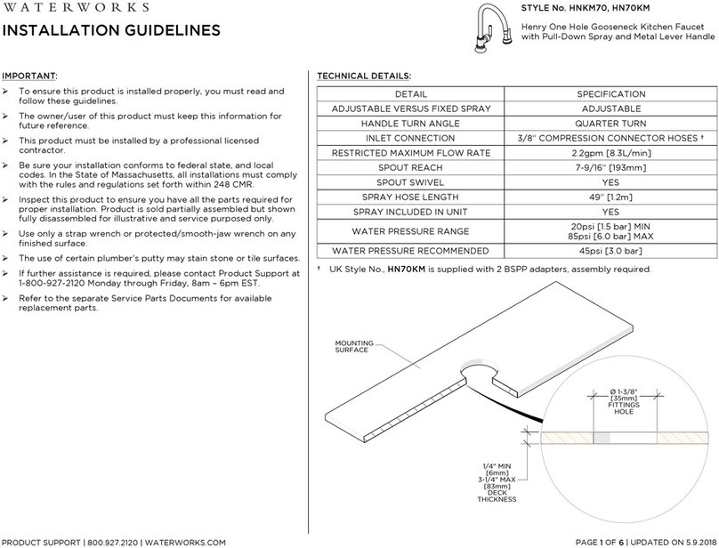
Waterworks Henry HNKM70 Instruction sheet
Waterworks

Waterworks Henry HNKM70 Instruction sheet

Waterworks UNWO20 Instruction sheet

Waterworks

Waterworks UNWO20 Instruction sheet

Waterworks HIGHGATE HGPB30 Instruction sheet

Waterworks

Waterworks HIGHGATE HGPB30 Instruction sheet

Waterworks HIGHGATE HGPB10 User manual
Waterworks

Waterworks HIGHGATE HGPB10 User manual

Popular Plumbing Product manuals by other brands

Moen SANI-STREAM 8797 manual

Moen

Moen SANI-STREAM 8797 manual

Grohe Allure Brilliant 19 784 manual

Grohe

Grohe Allure Brilliant 19 784 manual

Cistermiser Easyflush EVO 1.5 manual

Cistermiser

Cistermiser Easyflush EVO 1.5 manual

Kohler Triton Rite-Temp K-T6910-2A installation guide

Kohler

Kohler Triton Rite-Temp K-T6910-2A installation guide

BEMIS FNOTAB100 Installation instruction

BEMIS

BEMIS FNOTAB100 Installation instruction

Hans Grohe ShowerTablet Select 700 13184000 Instructions for use/assembly instructions

Hans Grohe

Hans Grohe ShowerTablet Select 700 13184000 Instructions for use/assembly instructions

Akw Stone Wash Basin Installation instructions manual

Akw

Akw Stone Wash Basin Installation instructions manual

Enlighten Sauna Rustic-4 user manual

Enlighten Sauna

Enlighten Sauna Rustic-4 user manual

Moen ShowHouse S244 Series quick start guide

Moen

Moen ShowHouse S244 Series quick start guide

Sanela SLWN 08 Mounting instructions

Sanela

Sanela SLWN 08 Mounting instructions

Franke 7612982239618 operating instructions

Franke

Franke 7612982239618 operating instructions

Heritage Bathrooms Granley Deco PGDW02 Fitting Instructions & Contents List

Heritage Bathrooms

Heritage Bathrooms Granley Deco PGDW02 Fitting Instructions & Contents List

Tres TOUCH-TRES 1.61.445 instructions

Tres

Tres TOUCH-TRES 1.61.445 instructions

STIEBEL ELTRON WS-1 Operation and installation

STIEBEL ELTRON

STIEBEL ELTRON WS-1 Operation and installation

Miomare HG00383A manual

Miomare

Miomare HG00383A manual

BELLOSTA revivre 6521/CR1 quick start guide

BELLOSTA

BELLOSTA revivre 6521/CR1 quick start guide

American Standard Heritage Amarilis 7298.229 parts list

American Standard

American Standard Heritage Amarilis 7298.229 parts list

BorMann Elite BTW5024 quick start guide

BorMann

BorMann Elite BTW5024 quick start guide

manuals.online logo
manuals.online logoBrands
  • About & Mission
  • Contact us
  • Privacy Policy
  • Terms and Conditions

Copyright 2025 Manuals.Online. All Rights Reserved.