Watkiss P2T User manual

P2T 2-Knife Trimmer
Unpacking and Installation Instructions
Issue 1b, June 2018
969-359

© Watkiss Automation Limited 2013-2018
All Rights Reserved.
Reproduction, adaptation, or translation without prior written permission is prohibited,
except as allowed under the copyright laws.
Warranty
The information contained in this document is subject to change without notice. Watkiss
Automation Limited makes no warranty of any kind with regard to this material, includ-
ing, but not limited to, the implied warranties of merchantability and fitness for a particu-
lar purpose.
Watkiss Automation Limited shall not be liable for errors contained herein or for inciden-
tal or consequential damage in connection with the furnishing, performance or use of
this material.

P2T 2-Knife Trimmer Page 1-1 - -
Issue 1b, June 2018
Effective for serial numbers WA/P2T/0010 onward.
CONTENTS
1. Before Installation
1.1 Introduction . . . . . . . . . . . . . . . . . . . . . . . . . . . . . . . . . . . . . . . . . . . 1-2
1.2 Safety . . . . . . . . . . . . . . . . . . . . . . . . . . . . . . . . . . . . . . . . . . . . . . . . 1-2
1.3 Warning Labels . . . . . . . . . . . . . . . . . . . . . . . . . . . . . . . . . . . . . . . . 1-3
1.4 Using a Fork-Lift Truck to Lift the P2T. . . . . . . . . . . . . . . . . . . . . . 1-5
1.5 Space Needed to Install the P2T . . . . . . . . . . . . . . . . . . . . . . . . . . 1-6
1.6 Tools Needed for Installation . . . . . . . . . . . . . . . . . . . . . . . . . . . . . 1-8
1.7 P2T Installation Hardware. . . . . . . . . . . . . . . . . . . . . . . . . . . . . . . . 1-9
1.8 BLM Installation Requirements . . . . . . . . . . . . . . . . . . . . . . . . . . 1-11
1.9 Machine Covers . . . . . . . . . . . . . . . . . . . . . . . . . . . . . . . . . . . . . . . 1-12
2. Unpack the P2T
2.1 Remove the Covers from the P2T . . . . . . . . . . . . . . . . . . . . . . . . . 2-2
2.2 Unload the P2T. . . . . . . . . . . . . . . . . . . . . . . . . . . . . . . . . . . . . . . . . 2-5
3. Prepare the BLM
3.1 Remove Covers from the BLM . . . . . . . . . . . . . . . . . . . . . . . . . . . . 3-2
3.2 Remove the Outfeed Stacker from the BLM . . . . . . . . . . . . . . . . . 3-4
3.3 Fit the Installation Hardware to the BLM . . . . . . . . . . . . . . . . . . . . 3-5
4. P2T Installation
4.1 Fit the P2T to the BLM. . . . . . . . . . . . . . . . . . . . . . . . . . . . . . . . . . . 4-2
4.2 Alignment of the P2T to the BLM . . . . . . . . . . . . . . . . . . . . . . . . . . 4-7
4.3 Fit the Covers to the P2T and to the BLM . . . . . . . . . . . . . . . . . . . 4-9
4.4 Fit the PBS/P2T Pivot Bracket to the BLM . . . . . . . . . . . . . . . . . 4-15
Appendix A
A.1 Check and Adjust the P2T for Level . . . . . . . . . . . . . . . . . . . . . . . A-2
A.2 Remove the LH, Bottom, Large Cover . . . . . . . . . . . . . . . . . . . . . A-4
Appendix B
B.1 Disconnect the P2T from the BLM . . . . . . . . . . . . . . . . . . . . . . . . B-2
B.2 Prepare the P2T . . . . . . . . . . . . . . . . . . . . . . . . . . . . . . . . . . . . . . . B-4
B.3 Prepare the Pallet . . . . . . . . . . . . . . . . . . . . . . . . . . . . . . . . . . . . . . B-6
B.4 Load the P2T onto the Pallet . . . . . . . . . . . . . . . . . . . . . . . . . . . . . B-9
B.5 Remove the Installation Hardware from the BLM . . . . . . . . . . . B-12
Appendix C
C.1 Adjust the Operating Voltage . . . . . . . . . . . . . . . . . . . . . . . . . . . . C-2
Appendix D

P2T 2-Knife Trimmer Page 1-2 - -
Issue 1b, June 2018

P2T 2-Knife Trimmer Page 1-1 CHAPTER 1 - Before Installation
Issue 1b, June 2018
CHAPTER 1 Before Installation
1.1 Introduction . . . . . . . . . . . . . . . . . . . . . . . . . . . . . . . . . . . . . . . . . . . . 1-2
1.1.1 This Manual . . . . . . . . . . . . . . . . . . . . . . . . . . . . . . . . . . . . . . . . . 1-2
1.1.2 Warnings . . . . . . . . . . . . . . . . . . . . . . . . . . . . . . . . . . . . . . . . . . . 1-2
1.2 Safety. . . . . . . . . . . . . . . . . . . . . . . . . . . . . . . . . . . . . . . . . . . . . . . . . 1-2
1.2.1 Weight . . . . . . . . . . . . . . . . . . . . . . . . . . . . . . . . . . . . . . . . . . . . . 1-2
1.3 Warning Labels . . . . . . . . . . . . . . . . . . . . . . . . . . . . . . . . . . . . . . . . . 1-3
1.4 Using a Fork-Lift Truck to Lift the P2T . . . . . . . . . . . . . . . . . . . . . . . . 1-5
1.5 Space Needed to Install the P2T . . . . . . . . . . . . . . . . . . . . . . . . . . . . 1-6
1.5.1 Space to Unload the P2T. . . . . . . . . . . . . . . . . . . . . . . . . . . . . . . 1-6
1.5.2 Space to Install the P2T. . . . . . . . . . . . . . . . . . . . . . . . . . . . . . . . 1-6
1.6 Tools Needed for Installation . . . . . . . . . . . . . . . . . . . . . . . . . . . . . . . 1-8
1.6.1 The Location of the Supplied Tools in the BLM . . . . . . . . . . . . . . 1-8
1.6.2 The Location of the Supplied Tools in the P2T. . . . . . . . . . . . . . . 1-8
1.7 P2T Installation Hardware . . . . . . . . . . . . . . . . . . . . . . . . . . . . . . . . . 1-9
1.7.1 Supplied with the P2T 2-Knife Trimmer . . . . . . . . . . . . . . . . . . . . 1-9
1.7.2 Additional Requirements . . . . . . . . . . . . . . . . . . . . . . . . . . . . . . . 1-9
1.7.3 PBS/P2T Pivot Bracket. Information. . . . . . . . . . . . . . . . . . . . . . 1-10
1.8 BLM Installation Requirements . . . . . . . . . . . . . . . . . . . . . . . . . . . . 1-11
1.9 Machine Covers. . . . . . . . . . . . . . . . . . . . . . . . . . . . . . . . . . . . . . . . 1-12
IMPORTANT:
• Make sure to read Section 1.7 - P2T Installation Hardware and Section 1.8 -
BLM Installation Requirements.
• Make sure you have the correct installation hardware for the P2T and that
you have fitted the required modifications to the BLM.

P2T 2-Knife Trimmer Page 1-2 CHAPTER 1 - Before Installation
Issue 1b, June 2018 Introduction
1.1 Introduction
1.1.1 This Manual
This manual describes how to install a P2T 2-Knife Trimmerto a PowerSquare.
• In this manual the PowerSquare is referred to as the BLM.
• In this manual the P2T 2-Knife Trimmer is referred to as the P2T.
1.1.2 Warnings
The warnings that follow are used in this manual
Warning: A WARNING message tells you that a procedure or operation
can be dangerous. To prevent injury, you must follow the instructions.
Caution: A CAUTION message tells you that a procedure or operation
can damage the machine or the product. To prevent damage, you must
follow the instructions.
1.2 Safety
Follow good Health and Safety procedures when you lift or move the equipment.
If the machine is operated when the covers are removed, be careful to prevent
personal injury.
Note: The disconnect device is the appliance inlet. See Figure 4:12.
1.2.1 Weight
• The installed weight of the P2T is 300kg (660lb).
• The shipping weight of the P2T is 360kg (792lb).
For information on the space needed to unload and install the P2T, see Section 1.5
- Space Needed to Install the P2T.

P2T 2-Knife Trimmer Page 1-3 CHAPTER 1 - Before Installation
Issue 1b, June 2018 Warning Labels
1.3 Warning Labels
The warning labels that follow are used in the P2T:
Warning Label Description Location Part No.
Indicates the danger of crush or cut injuries if fingers or other
body parts are inserted into this part of the machine. Black
figure on yellow background.
Trimmer blades. 500-248
Mains input voltage.
Black figure on yellow background.
On the outside of the
mains input panel next to
the mains input socket.
500-009
Safety Earth.
White figure on a green background.
On the inside of the mains
input panel.
500-254
Earth continuity.
White figure on a green background.
On the mains input panel
next to the earth terminal
post.
500-006
General Hazard - consult the service manual.
Black and yellow figure with blue and white figure on a white
background.
On the LH and RH crank
links.
500-373
Electrical Hazard - consult the service manual.
Black and yellow figure with blue and white figure on a white
background.
On the top edge of the
mains power and inverter
box.
500-374

P2T 2-Knife Trimmer Page 1-4 CHAPTER 1 - Before Installation
Issue 1b, June 2018 Warning Labels
TABLE 1:1. Warning Labels
Use only at altitudes not more than 2000m above sea level.
仅适用于海拔 2000m 以下地区安全使用
Black figure on a silver background.
On the serial number label.
Outside of the machine
near to the mains power
inlet.
-
Use only in non-tropical conditions.
仅适用于非热带气候条件下安全使用
Black figure on a silver background.
On the serial number label.
Outside of the machine
near to the mains power
inlet.
-
2000m
P2T 2-Knife Trimmer Page 1-5 CHAPTER 1 - Before Installation
Issue 1b, June 2018 Using a Fork-Lift Truck to Lift the P2T
1.4 Using a Fork-Lift Truck to Lift the P2T
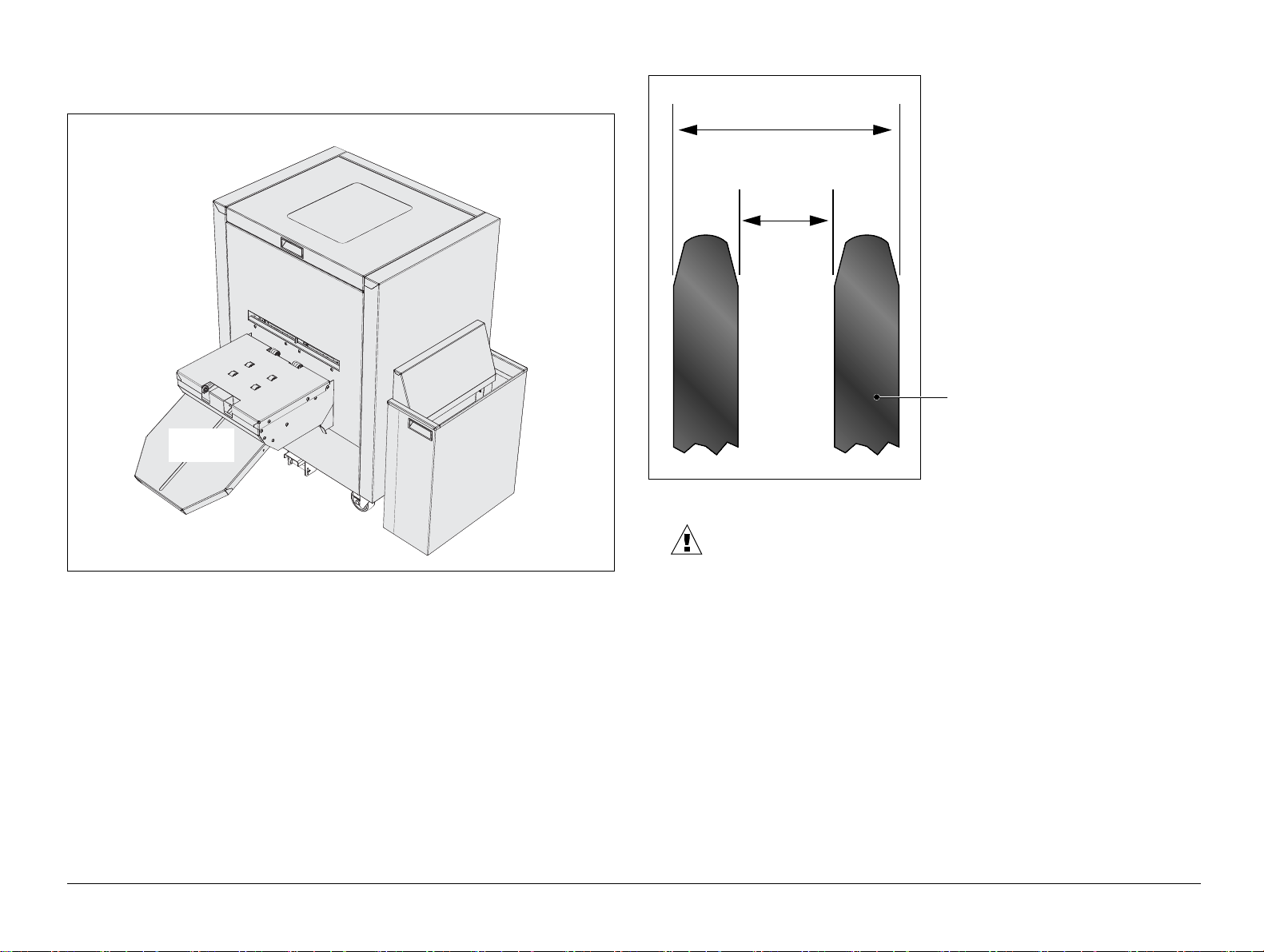
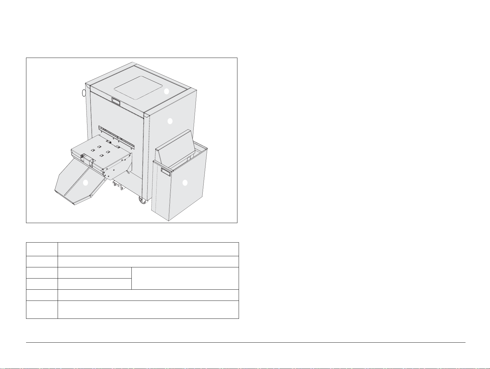
Figure 1:1. Machine orientation
Note: The trim bin can be installed on the RHS for left-to-right booklet makers or
on the LHS for right-to-left booklet makers.
Figure 1:2. Distance between the forks
Caution:
• The installed weight of the P2T is 300 kg (660 lb).
• The shipping weight of the P2T is 360 kg (792 lb).
You can lift the P2T directly with a fork-lift or pallet truck, but where possible, lift the
pallet and P2T together.
If you lift the P2T directly, then you must:
• Fold the outfeed stacker, see Section B.1
• Insert the forks under the front or rear of the P2T. Do not insert the forks under
the LH side or RH side. See Figure 1:1.
• If the distance between the forks is adjustable, then adjust the forks to the
dimensions given. See Figure 1:2.
Front
Rear
Trim bin
LH
RH
Outfeed
stacker
A
B
Dimension A:
Maximum 450mm (17.5”)
Dimension B:
Minimum 140mm (5.5”)
Fork

P2T 2-Knife Trimmer Page 1-6 CHAPTER 1 - Before Installation
Issue 1b, June 2018 Space Needed to Install the P2T
1.5 Space Needed to Install the P2T
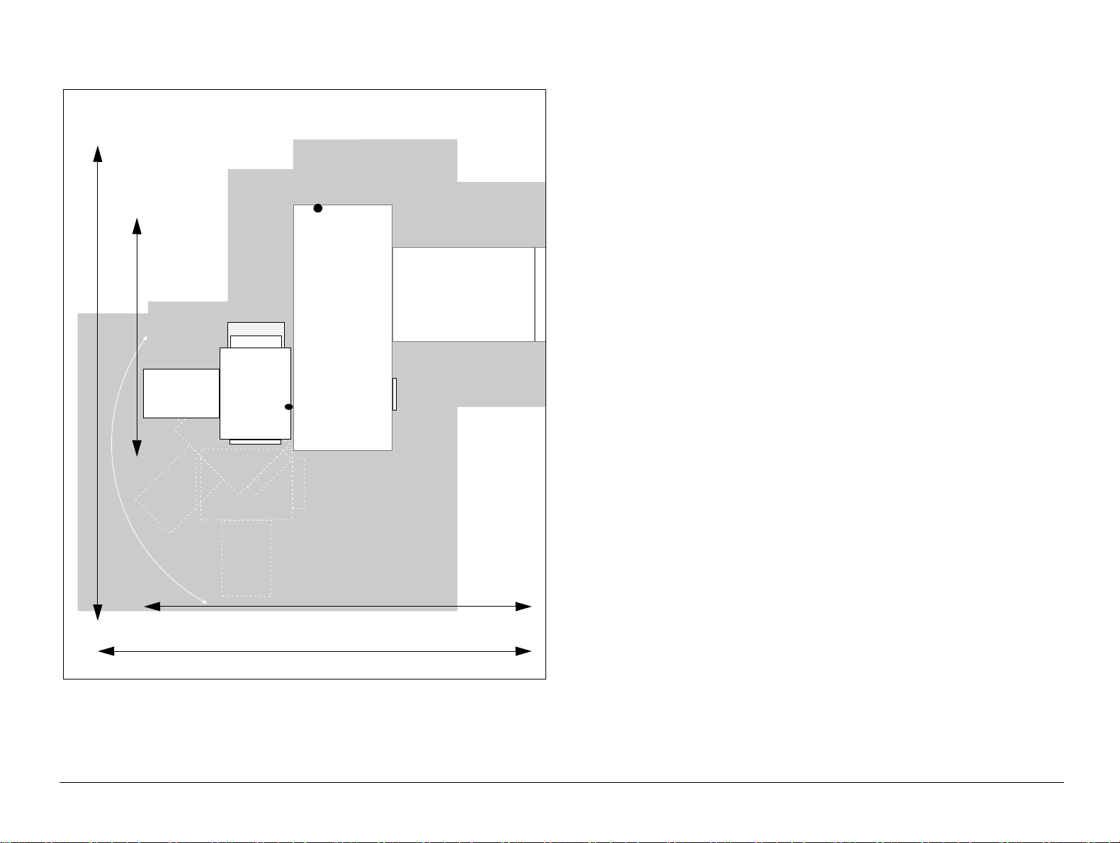
1.5.1 Space to Unload the P2T
CAUTION: Always unload the P2T from the pallet in the direction shown
in Figure 1:3.
Put the pallet in enough space to fit the ramps and unload the P2T.
• You need a minimum length of 3735 mm (147 inches) and a minimum
width of 1100 mm (43 inches).
See Figure 1:3.
Figure 1:3. The space needed to unload the P2T
1.5.2 Space to Install the P2T
1.5.2.1 PowerSquare and P2T 2-Knife Trimmer. Left-to-Right.
3735 mm, 147"
NOT TO SCALE
Input for Mains Power Supply
for BLM
BLM500/
BLM550
Connecting Bridge
500 mm, 20" is required on all sides for access.
The height is 1330mm, 52.5". An additional 500 mm, 20" is required above the machine for
service access
1895 mm, 74.5"
1870 mm, 74"
3505 mm, 138" (outfeed extended, 3170mm, 125" (outfeed folded)
P2T
Input for Mains
Power Supply
P2T 2-Knife Trimmer Page 1-7 CHAPTER 1 - Before Installation
Issue 1b, June 2018 Space Needed to Install the P2T
1.5.2.2 PowerSquare and P2T 2-Knife Trimmer. Right-to-Left.
BLM600
Connecting
Bridge
P2T Trimmer
Input for Mains
Power Supply
Input for Mains Power Supply
Maintenance area: 3470 mm, 137"
2970 mm, 117"
1870 mm, 74"
Maintenance area: 3520 mm, 139"
NOT TO SCALE
P2T 2-Knife Trimmer Page 1-8 CHAPTER 1 - Before Installation
Issue 1b, June 2018 Tools Needed for Installation
1.6 Tools Needed for Installation
• Allen keys: 3, 4, 5, 8 mm
• Spanners: 8, 10, 17 mm
• 600mm steel rule or tape measure
• Spirit level - max 250 mm. See Accuracy of the Spirit Level for reference
• Wire cutters - supplied with the BLM. See Section 1.6.1.
• 14 mm socket - supplied with the BLM. See Section 1.6.1.
• 17 mm socket
• Ratchet handle - supplied with the BLM. See Section 1.6.1.
• Knife or scissors - to cut straps and plastic-wrap
• Masking tape
• Pen or pencil
• Wheel gauge tool - supplied with the P2T. See Section 1.6.2.
1.6.1 The Location of the Supplied Tools in the BLM
Figure 1:4. Location of the supplied tools in the BLM
The ratchet-handle, 14 mm socket and wire cutters are stored inside the BLM and
found when you open the BLM main deck.
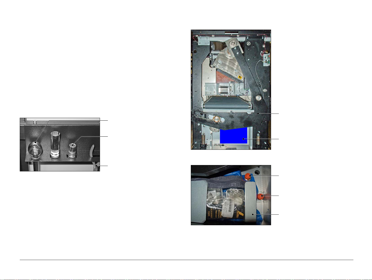
1.6.2 The Location of the Supplied Tools in the P2T
Figure 1:5. Location of the tool bag for the P2T
Figure 1:6. Tool kit fixing
The tool kit for the P2T is in a bag behind the LH side cover.
See Section 2.1 for LH side cover removal procedure.
Ratchet-handle
14mm socket
Wire cutters
LH crank link
Location of the tool bag
Orange handscrew that holds the tool
bag
Orange handscrew that holds the
blade lift bracket
Blade lift bracket
P2T 2-Knife Trimmer Page 1-9 CHAPTER 1 - Before Installation
Issue 1b, June 2018 P2T Installation Hardware
1.7 P2T Installation Hardware
Important:
• Also see: Section 1.8 - BLM Installation Requirements
1.7.1 Supplied with the P2T 2-Knife Trimmer
1.7.1.1 Mains power connection
P2T connection: IEC60320 C19 - cable and plug supplied with the machine.
• 740-016 UK : BS 1363 2.5M
• 740-017 Europe : IEC83 'Schuko' 2.5M
• 740-018 North America / Japan : NEMA 6-15 2.5M
• For other areas, contact supplier for the correct cable.
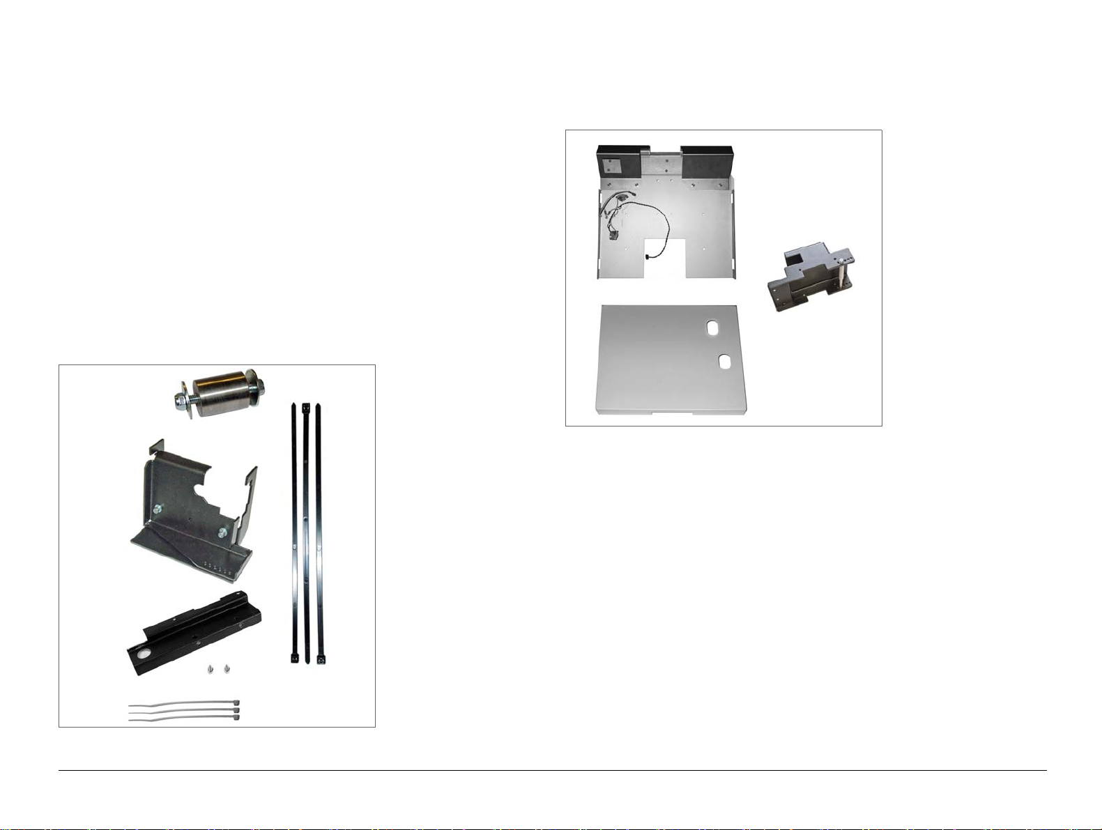
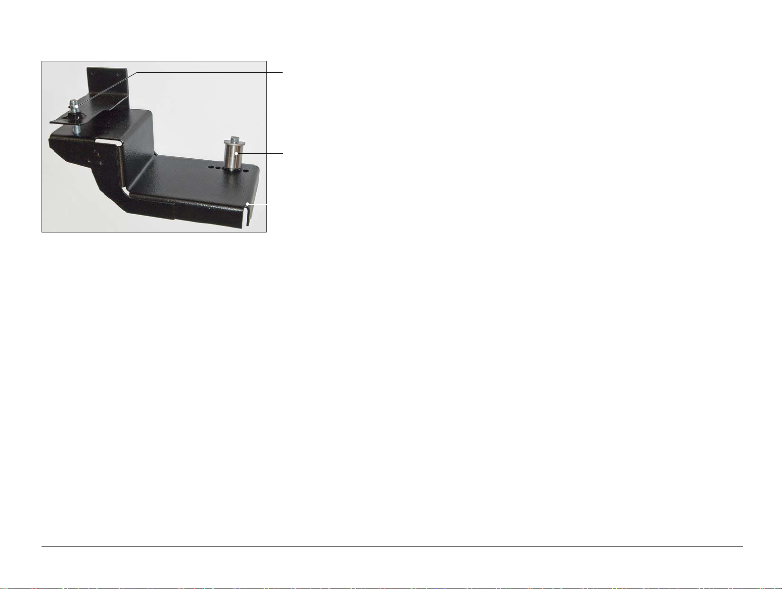
1.7.1.2 Pivot Kit
• 914-569 KIT, (P2T) PIVOT KIT x 1. See Figure 1:7.
Figure 1:7. 914-569 P2T pivot kit - included with the P2T
1.7.2 Additional Requirements
1.7.2.1 P2T/PBS Interface Kit for BLM
Figure 1:8. P2T/PBS Interface Kit for BLM. Supplied with the BLM600.
Note: If there is a PBS, serial number WA/PBS/0060 or later already installed, then
you do not need an additional interface kit.
1.7.2.2 For territories with supply voltage below 225V AC
• 072-306 P2T, AUX TRANSFORMER ASSY KIT x 1
See Section C.1 for reference.
1. Pivot post with M5x40
cap-head screw, M5
nyloc nut and 2 x M5
washers 12.5mm O/D
2. Pivot location bracket
with 2 x M5x12 cap-
head screws and
spring washers.
3. Pivot clamp bracket
4. Pivot bracket with 2 x
M5x12 cap-head
screws and spring
washers.
5. 3 x long cable ties
6. 3 x short cable ties
7. Cover mounting
bracket and 8 x M5x12
cap-head screws with
shakeproof washers
8. Docking latch assem-
bly and 2 x M5x12 cap-
head screws with
shakeproof washers
9. Outfeed cover and 2 x
M5x10 button-head
screws with shakeproof
washers
P2T 2-Knife Trimmer Page 1-10 CHAPTER 1 - Before Installation
Issue 1b, June 2018 P2T Installation Hardware
1.7.3 PBS/P2T Pivot Bracket. Information.
When the P2T is used with a PBS, the PBS/P2T pivot bracket is used instead of
the docking pivot pin supplied with the PBS. See Figure 1:9.
The PBS/P2T pivot bracket is supplied in:
• 940-180 KIT, PBS+P2T MISC CONFIGURATION PARTS or the
• 072-32x KIT, PBS/P2T TRIMMINGS CONVEYOR
Fitting instructions are supplied in the PBS Unpacking and Installation Instructions.
PBS/P2T pivot bracket
Pivot post
M8x35 cap-head screw
Figure 1:9. PBS/P2T pivot bracket

P2T 2-Knife Trimmer Page 1-11 CHAPTER 1 - Before Installation
Issue 1b, June 2018 BLM Installation Requirements
1.8 BLM Installation Requirements
IMPORTANT:
In addition to the installation hardware for the P2T, the BLM, dependent on serial
number, can need modification. Fit the modifications as shown below.
BLM Serial No. WA/PSQ/0800 onward:
• Modification is not needed.
BLM Serial No. WA/PSQ/0500 - 0799:
• 940-161 KIT, PSQ MOD 61, UPDATES REQ'D FOR P2T
• 940-162 KIT, PSQ MOD 62, R4.1 SOFTWARE UPDATES
BLM Serial No. WA/PSQ/0120 - 0499:
• 940-139 KIT, PSQ MOD 54, TRIM STRIP EJECTION
• 940-161 KIT, PSQ MOD 61, UPDATES REQ'D FOR P2T
• 940-162 KIT, PSQ MOD 62, R4.1 SOFTWARE UPDATES
P2T 2-Knife Trimmer Page 1-12 CHAPTER 1 - Before Installation
Issue 1b, June 2018 Machine Covers
1.9 Machine Covers
This section identifies the machine covers, some of which are removed in
installation procedures.
Figure 1:10. Machine covers_1
TABLE 1:2. Machine covers_1
Cover Description
Top cover
LH side cover Note: These 2 covers are not
interchangeable.
RH side cover
Outfeed stacker
Trim bin. Fitted to the RHS for Left-to-Right machines. Fitted to the
LHS for Right-to-Left machines.


P2T 2-Knife Trimmer Page 2-2 CHAPTER 2 - Unpack the P2T
Issue 1b, June 2018 Remove the Covers from the P2T
2.1 Remove the Covers from the P2T
Important: Before you unpack the P2T, check the following:
• Check the ‘Tip and Tell’ indicator on the pallet. The ‘Tip and Tell’ indicator
shows that the machine was kept in the vertical position and did not fall.
• Check the packaging is not damaged.
Important: When the P2T is unpacked, check the following:
• Check that the trim bin is present. The trim bin can be shipped separately and
contains components needed for the installation. See Figure 2:1.
Cautions:
Caution: When you remove the packaging from the P2T, make sure
you do not damage the paintwork.
Caution: Keep all of the packaging material. To prevent damage to the
P2T when shipped, you must use the correct packaging material.
Caution: When you remove the covers from the P2T, make sure you do
not damage the paintwork. Make sure you put the covers on smooth
clean surfaces to decrease the risk of damage.
Tools:
• Allen key: 4mm
• Wirecutters - supplied with the BLM. See Section 1.6.1.
• Knife or scissors to cut straps and plastic-wrap
• 14 mm socket - supplied with the BLM. See Section 1.6.1.
• Ratchet handle - supplied with the BLM. See Section 1.6.1.
• Steel rule
Figure 2:1. Machine covers
Figure 2:2. Remove a side cover from the P2T
LH side cover
Top cover
RH side cover
Trim bin. Fitted to the RHS for Left-
to-Right machines. Fitted to the LHS
for Right-to-Left machines.
Outfeed stacker
Top cover (open)
Side cover
M5 cap-head screw
P2T 2-Knife Trimmer Page 2-3 CHAPTER 2 - Unpack the P2T
Issue 1b, June 2018 Remove the Covers from the P2T
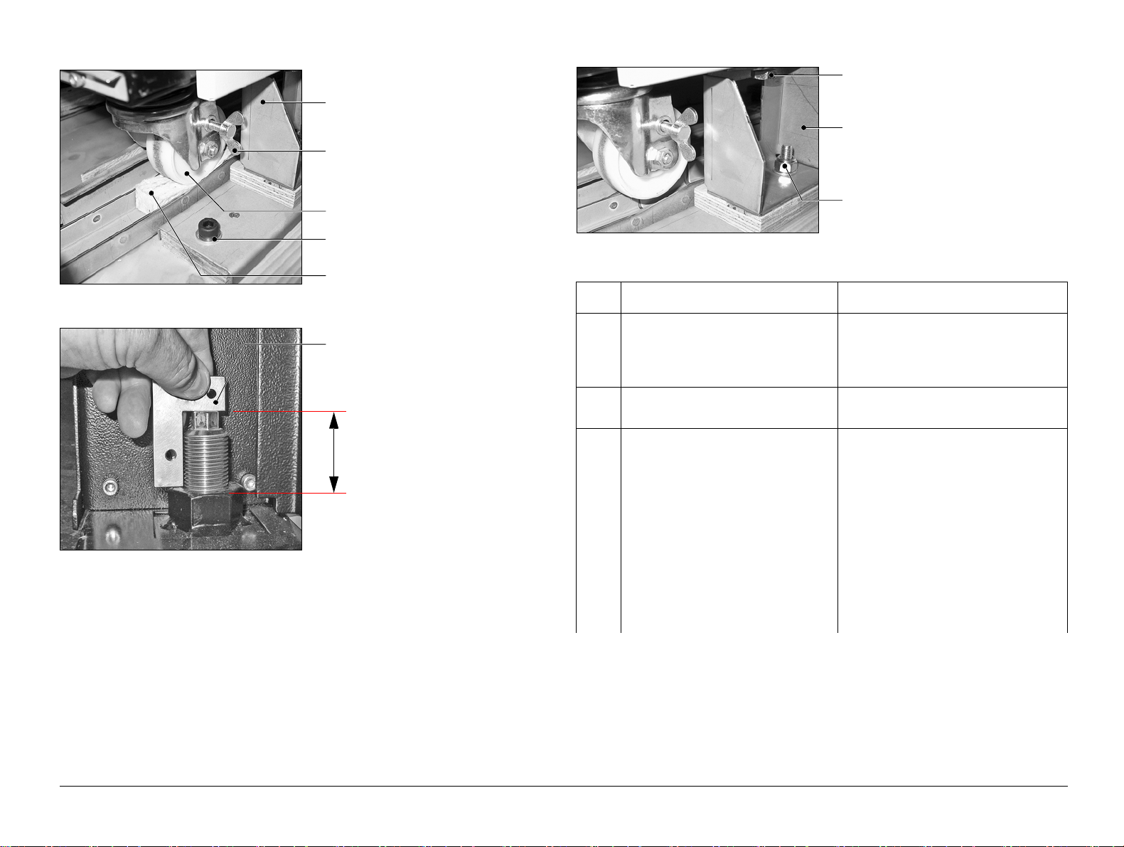
Figure 2:3. Castor
Figure 2:4. Height of the exposed thread
Figure 2:5. Locations of the shipping bolts
Transit bracket
Brake
Castor
Pivot for bracket assembly.
DO NOT REMOVE.
Foam rubber packing
Use the wheel gauge tool
supplied in the tool kit to set
this dimension.
Wheel gauge tool (43mm)
Step Action Information
1 Remove the outer packaging
material from the P2T.
Keep all of the packaging materials.
To prevent damage to the P2T when
shipped, you must use the correct
packaging materials.
2 Remove the plastic-wrap from
around the P2T.
3 Remove the RH side cover and
the LH side cover.
See Figure 2:1.
and Figure 2:2.
• Open the top cover of the P2T.
The top cover is held open by
gas-struts.
• Remove the screw from the
middle of the top edge of the two
covers.
• Lift each cover by approximately
20 mm and then pull toward you
to remove.
• Close the top cover.
Shipping bolt
Fixing nut for the transit bracket.
DO NOT REMOVE
Transit bracket
P2T 2-Knife Trimmer Page 2-4 CHAPTER 2 - Unpack the P2T
Issue 1b, June 2018 Remove the Covers from the P2T
4 Release the castors. See Figure 2:3.
• Remove the foam rubber packing
from under each of the 4 castors.
Keep the foam rubber packing
with the rest of the packing
material for the P2T.
• Cut and discard the cable ties
that hold the castors in position.
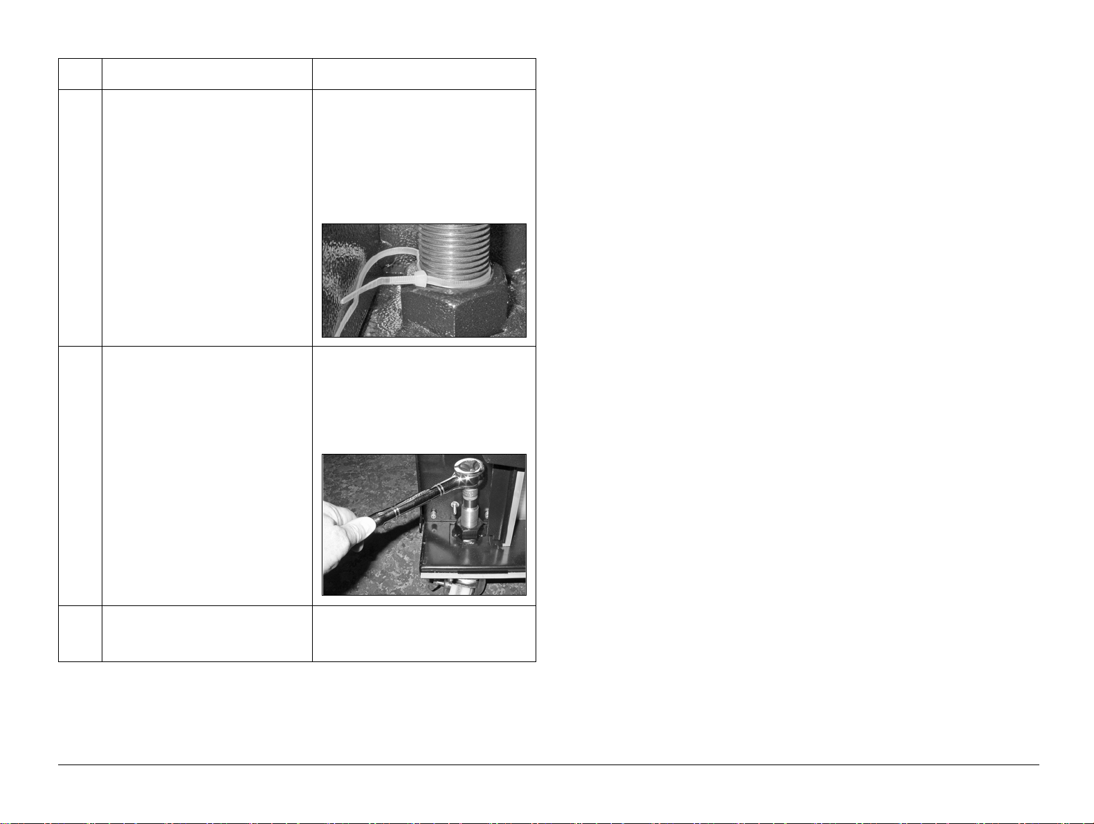
5 Adjust the castors to the correct
height to unload the P2T from the
pallet.
•See Figure 2:4.
To unload the P2T from the
pallet, you must use the supplied
wheel gauge tool to set the
height of the 4 adjustable-
castors.
6IMPORTANT:
Remove the 4 shipping bolts
that hold the P2T to the pallet.
See Figure 2:5.
DO NOT remove the nuts that hold
the brackets to the pallet.
Step Action Information
Other manuals for P2T
1
Table of contents
Other Watkiss Trimmer manuals


