WATT AGE Crazy MAX EP User manual

1
Visit our website at http://watt-age.globalhobby.com for information on other Wattage products
The Wattage Crazy Max EP is distributed exclusively by Global Hobby Distributors 18480 Bandilier Circle, Fountain Valley, CA 92728
FOR YOUR INFORMATION
To make your modeling experience totally enjoyable, we recommend that you get experienced, knowledgeable help with
assembly and during your first flights. Your local hobby shop has information about flying clubs in your area whose
membership includes qualified instructors. If there is no hobby shop in your area, we recommend that you contact the
AMAat the address below. They will be able to help you locate a flying field near you.
Academy of Model Aeronautics
5151 East Memorial Drive
Muncie IN 47302-9252
(800) 435-9262
www.modelaircraft.org
Specifications:
●Wing Span: 35 inches
●Wing Area: 284 square inches
●Length: 26 inches
●Weight: 12 - 13 ounces Ready to Fly
●Motor: 370 Electric with Gear Box & Propeller
●Functions: Ailerons, Elevator, Rudder & Throttle
●Radio: 4 or More Channel Micro System
Kit Product Number 128432
All contents copyright © 2001, Global Hobby Distributors Version V1.0 September 2001

2Need help or have any questions? Call us at 1-714-963-0329 or send us an email to service@globalhobby.net
ThisR/Cairplaneisnotatoy!Ifmisusedorabused,itcancauseseriousbodilyinjuryand/ordamagetoproperty. Flyonly
inopenareasandpreferablyatadedicatedR/C flying site. Wesuggest having a qualifiedinstructorcarefullyinspectyour
airplane before its first flight. Please carefully read and follow all instructions included with this airplane, your radio
control system and any other components purchased separately.
TABLE OF CONTENTS
SAFETY WARNING
OUR GUARANTEE:
Wattageguaranteesthis kit to befreefromdefects in both materialandworkmanship, at the dateofpurchase. Thisdoes
not cover any component parts damaged by use, misuse or modification. In no case shall Wattage's liability exceed
the original cost of the purchased kit.
In thatWattage has no control over the final assembly or material used for final assembly, no liability shall be assumed
foranydamageresultingfromtheuseby the user of the final user-assembled product. By theactofusingthefinaluser-
assembled product, the user accepts all resulting liability.
Safety Warning..........................................................................................................2
Introduction ...............................................................................................................3
Our Recommendations..............................................................................................4
Kit Contents...............................................................................................................5
Replacement Parts.....................................................................................................6
Tools and Supplies Required ....................................................................................7
Metric Conversion Chart...........................................................................................7
Section 1: Fuselage Assembly ..........................................................................8
Section 2: Horizontal Stabilizer ......................................................................10
Section 3: Vertical Stabilizer...........................................................................13
Section 4: Motor and Gear Box Installation...................................................15
Section 5: Elevator and Rudder Pushrod Installation 17
Section 6: Wing Assembly..............................................................................19
Section 7: Aileron Pushrod Installation..........................................................22
Section 8: Wing Mounting ..............................................................................26
Section 9: Final Assembly ..............................................................................27
Section 10: Balancing the Crazy Max EP......................................................30
Section 11: Lateral Balancing ........................................................................31
Section 12: Control Throws ...........................................................................31
Section 13: Computer Radio Setup ................................................................31
Section 14: Preflight Check and Safety .........................................................32
Section 15: Flying the Crazy Max EP............................................................34
Product Evaluation Sheet........................................................................................35

3
Visit our website at http://watt-age.globalhobby.com for information on other Wattage products
Thisinstructionmanualisdesigned to guide you through theentirefinalassemblyprocessofyour new airplane in the
least amount of time possible. Along the way you'll learn how to properly assemble your new airplane and also learn
tips that will help you in the future. We have listed some of our recommendations below. Please read through them
before beginning assembly.
The Crazy Max EP is constructed of Closed Cell Foam. It is very important that you use no
solvents, Cyanoacrylate (C/A) glue, or paint that can damage foam. If any of these chemicals
comes in contact with the foam parts, the parts will be destroyed and will not be covered under
warranty. Use only epoxy where glue is required. If you decide to paint the foam parts, use an
acrylic paint that will not attack foam and always test on a scrap piece first.
●Please read through each step before beginning
assembly. You should find the layout very complete
andstraightforward. Our goal is toguideyou through
assembly without any of the headaches and hassles
that you might expect.
●There are check boxes next to each step. After
you complete a step, check off the box. This will
help prevent you from losing your place.
●Cover your work table with brown paper or a soft
cloth, both to protect the table and to protect the parts.
●Keep a couple of small bowls or jars handy to put
the small parts in after you open the accessory bags.
●We're all excited to get a new airplane in the air, but
take your time. This will ensure you build a straight,
strong and great flying airplane.
●If you come across this symbol ☛, it means that
this is an important point or an assembly hint.
If you should find a part missing or damaged, or have any questions about assembly, please
contact us at the address below:
Wattage Customer Service
18480 Bandilier Circle
Fountain Valley CA 92728
Phone: (714) 963-0329 Fax: (714) 964-6236 E-mail: service@globalhobby.net
INTRODUCTION
Thank you for purchasing the new Wattage Crazy Max EP. Before completing the final
assembly of your new airplane, please carefully read through this instruction manual
in its entirety. Doing so will ensure success the first time around!
Wattage Crazy Max EP Features:
●Compact, Lightweight Design for Small Field Flying
●Fully Symmetrical Wing for Exciting Flight Characteristics
●Large Control Surfaces for Extreme Aerobatics
●Optional Dual Aileron Servos Allows Mixing Capabilities
●Fiberglass Stabilizer Spar to Prevent Twisting and Flutter
●Powerful 370 Electric Motor with Gear Box and Propeller Included
●Includes Hardware for Dual or Single Aileron Servo Setups
●Colorful Decal Sheet Enhances Appearance
●All Hardware Included
●Quick & Easy Assembly - Over 50 Photos & Drawings Included

4Need help or have any questions? Call us at 1-714-963-0329 or send us an email to service@globalhobby.net
This section lists the items you will need to purchase for your new Crazy Max EP. These suggestions are not set in stone,
but they will provide you with a good, proven starting point.
OUR RECOMMENDATIONS
For General Sport Flying We Recommend:
Cirrus MRX-4 Micro Receiver
Hitec Single Conversion RX Crystal
P/N 444052 Cirrus CS-10 Micro Servos (3)
P/N 128484 Wattage IC-15A ESC
P/N 128538 Wattage 8 Cell 800Mah NiMH Flight Battery
P/N 130103 Wattage 7-8 Cell 1 ampAC/DC Peak Charger
IMPORTANT - PLEASE READ
The Wattage Crazy Max EP is a high-performance, aerobatic electric-powered model. When choosing accessories like
servos, ESC, and receiver, it's very important to take the weight of these items into consideration. Remember, the lighter
the overall weight of the finished airplane, the better the airplane will perform.
Servos
The servos you use should be the lightest available, yet still have an adequate amount of torque. We suggest using servos
that weigh no more than 0.19 ounces and have a torque rating of no less than 7.0 ounces per square inch.
Receiver
The receiver should be as light as possible, preferably 1/2oz. or less. Most four channel micro receivers will be a good
choice. If you plan on using the Hitec 555 Micro receiver, we suggest removing the case to reduce the receiver's weight.
If you do remove the case from your receiver we strongly suggest wrapping the receiver with heat-shrink material to
protect the internal components.
Special Note for Receiver:
If you plan on using two separate aileron servos so you can have mixing capabilities, make sure the receiver you
choosesupportsthe mixing capabilities of yourtransmitter. Most4 channel receivers don't, soyou'llhaveto use a six
or more channel receiver. If it has a case, remove it to save weight.
Electronic Speed Control
The ESC you choose should be capable of handling no less than 15 amps continuous current. Again, lighter is better.
Your ESC should weigh no more than 1 ounce including the wiring and switch.
Special Note for ESC
Most 15amp ESCs don't support the use of more than three servos. If you use four servos in your Crazy Max you
should use a 30amp ESC. The added weight will be minimal.
Flight Battery
For the best flight performance the battery used should be an 8 cell 800Mah 5/4AAA NiMH pack. You can use NiCD
batteries but they are heavier and you won't get as long a flight time. NiMH batteries don't give quite as much power, but
still plenty for the Crazy Max and, most importantly, they are lighter and give significantly more flight time.

5
Visit our website at http://watt-age.globalhobby.com for information on other Wattage products
For Aerobatic Flying with Mixing Capability We Recommend:
Hitec 8 Channel Super-Slim Receiver (remove case for lighter weight)
Hitec Dual Conversion RX Crystal
P/N 444052 Cirrus CS-10 Micro Servos (4)
P/N 128486 Wattage IC-30A ESC
P/N 128538 Wattage 8 Cell 800Mah NiMH Flight Battery
P/N 130103 Wattage 7-8 Cell 1 ampAC/DC Peak Charger
IMPORTANT
The part numbers listed for the Cirrus servos andWattage ESCs are compatible with Hitec and JR receivers. These items
are also available with connectors that are compatible with Futaba and Airtronics receivers.
When you purchase a Hitec receiver, you must also purchase the Hitec brand crystal compatible with the receiver. The
crystal must also be on the same frequency as your transmitter. Note that the Cirrus MRX-4 Micro Receiver uses a single
conversion Hitec crystal. A dual conversion crystal will not work with it.
We have organized the parts as they come out of the box for easier identification during assembly. Before you begin
assembly, group the parts like we list them below. This will ensure that you have all of the parts before you begin
assembly and it will also help you become familiar with each part. If you find any parts missing or damaged, please
contact us below:
AIRFRAME ASSEMBLIES
❑{1} Fuselage w/Plywood Motor Mount
❑{1} Left Wing Panel
❑{1} Right Wing Panel
❑{1} Horizontal Stabilizer w/Elevator
❑{1} Vertical Stabilizer w/Rudder
❑{2} Sheet-Foam Ailerons
KIT CONTENTS
Wattage Customer Service
18480 Bandilier Circle
Fountain Valley CA 92728
Phone: (714) 963-0329 Fax: (714) 964-6236 E-mail: service@globalhobby.net
LANDING GEAR ASSEMBLY
❑{1} Prebent Main Gear Wire
❑{2} Main Gear Wheels
❑{2} Nylon Wheel Retainers
MOTOR ASSEMBLY
❑{1} 370 Motor w/Gear Box
❑{1} 7.5 x 5 Propeller
❑{1} 3mm Flat Washer
❑{2} 3mm Hex Nuts
❑{3} 3mm x 12mm Wood Screws
Kit Contents Continued on Next Page

6Need help or have any questions? Call us at 1-714-963-0329 or send us an email to service@globalhobby.net
Wattage stocks a complete line of replacement parts for your Crazy Max EP. Listed below are the replacement parts that
are available along with their respective part numbers for easy ordering convenience. We suggest ordering directly
from your local dealer. If your dealer does not stock Wattage products, you can order directly from us at the address
shown below:
REPLACEMENT PARTS
Global Hobby Distributors
18480 Bandilier Circle
Fountain Valley CA 92728
Phone: (714) 963-0329 Fax: (714) 964-6236
PUSHROD ASSEMBLIES
❑{2} 1.5mm x 400mm Threaded Pushrod Wires
❑{2} 1.5mm x 150mm Threaded Pushrod Wires
❑{4} Nylon Control Horns w/Backplates
❑{4} Nylon Clevises
❑{1} Aileron Servo Mounting Board - 2 Parts
WING MOUNTING ASSEMBLIES
❑{1} Molded Plastic Wing Mount
❑{1} 3mm x 60mm Wood Dowel
❑{1} 3mm x 70mm Wood Dowel
❑{1} Wing Reinforcement Board - 2 Parts
❑{2} 180mm Long Adhesive Strips
❑{2} Rubber Bands
MISCELLANEOUS ITEMS
❑{1} Fiberglass Reinforcement Spar
❑{1} Prebent Elevator Joiner Wire
❑{1} Elevator Reinforcement Board - 2 Parts
❑{2} 430mm Long Adhesive Strips
WARNING
We do not suggest storing your airplane in an extremely hot environment (like the back of your car in
direct sunlight) for any length of time. The extreme heat could cause the foam to melt and possibly
damage the fragile components of the radio system, ESC or batteries.
❑{1} 37mm x 50mm Sheet-Foam
❑{1} Fuselage Reinforcement Board
❑{1} Decal Sheet
❑{1} Double-Sided Tape
Instruction Manual - 145340
Wing Set - 145341
Fuselage Set - 145342
Stabilizer Set - 145343
Control Linkage Set - 145344
Decal Set - 145345
Motor, Gearbox & Propeller - 145346
Landing Gear Set - 145336
370 Electric Motor - 131350
Gear Box Assembly - 131371
Spur Gear & Pinion Set - 131376
7.5 x 5 Propeller - 131381

7
Visit our website at http://watt-age.globalhobby.com for information on other Wattage products
❑Kwik Bond 5 Minute Epoxy # 887560
❑# 0 Phillips Head Screwdriver
❑# 1 Phillips Head Screwdriver
❑Magnum Z-Bend Pliers # 237473
❑Wire Cutters
❑Needle Nose Pliers
❑Adjustable Wrench
❑Excel Modeling Knife # 692801
❑Scissors
❑Electric Drill
❑Assorted Drill Bits
❑Ruler
❑Pencil
❑Masking Tape
❑Builder's Triangle
❑220 Grit Sandpaper w/Sanding Block
❑Paper Towels
❑Rubbing Alcohol
❑NHP Epoxy Mixing Sticks # 864204
❑NHP Epoxy Mixing Cups # 864205
❑K&S 30 Watt Soldering Iron # 598120
❑Kester Solder # 398505
❑Hair Dryer
TOOLS AND SUPPLIES REQUIRED
To convert inches into millimeters: Inches x 25.4 = mm
1/64" = .4mm
1/32" = .8mm
1/16" = 1.6mm
3/32" = 2.4mm
1/8" = 3.2mm
5/32" = 4.0mm
3/16" = 4.8mm
1/4" = 6.4mm
3/8" = 9.5mm
1/2" = 12.7mm
5/8" = 15.9mm
3/4" = 19.0mm
1" = 25.4mm
2" = 50.8mm
3" = 76.2mm
6" = 152.4mm
12" = 304.8mm
18" = 457.2mm
21" = 533.4mm
24" = 609.6mm
30" = 762.0mm
36" = 914.4mm
METRIC CONVERSION CHART
IMPORTANT
The soldering iron and solder listed above are optional. Depending on the ESC and flight battery you have chosen to use,
theymay not have plugs thatare compatible withthe plug thatcomes preinstalled on the motor. If this is thecase you will
need to solder a compatible plug onto the motor or, better yet, solder the ESC leads directly to the motor.
WARNING
The Crazy Max EP is constructed of Closed Cell Foam. It is very important that you use no solvents,
Cyanoacrylate (C/A) glue, or paint that can damage foam. If any of these chemicals comes in contact
with the foam parts, the parts will be destroyed and will not be covered under warranty. Use only epoxy
where glue is required. If you decide to add painted details to the Crazy Max, use acrylic-based paints
and always test the paint on a scrap piece first.

8Need help or have any questions? Call us at 1-714-963-0329 or send us an email to [email protected]
❑Kwik Bond 5 Minute Epoxy
❑Excel Modeling Knife
❑Scissors
❑1/8" Drill Bit
❑Ruler
YOU'LL NEED THE FOLLOWING PARTS:
❑{1} Fuselage w/Plywood Motor Mount
❑{1} 3mm x 60mm Wood Dowel
❑{1} 3mm x 70mm Wood Dowel
SECTION 1: FUSELAGE ASSEMBLY
❑{1} Fuselage Reinforcement Board
❑{1} Decal Sheet
YOU'LL NEED THE FOLLOWING SUPPLIES:
❑Pencil
❑Paper Towels
❑Rubbing Alcohol
❑NHP Epoxy Mixing Sticks
❑NHP Epoxy Mixing Cups
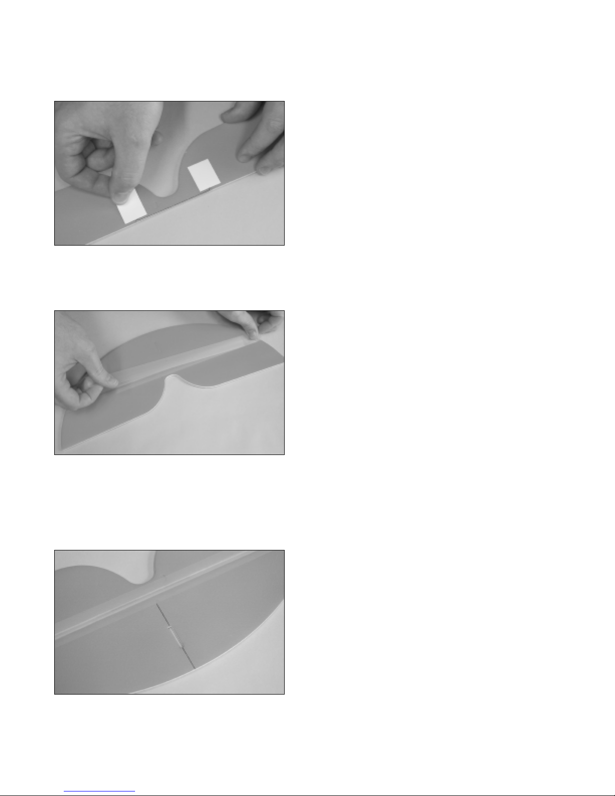
Step 1: Installing the Truss Decal
❑Using a pair of scissors, cut out the fuselage truss decal
along its outer edges.
❑Carefully apply the decal to the fuselage, making sure
that the alignment marks at both the front and the back of the
decal line up with the edges of the fuselage.
IMPORTANT
The back edge of the decal should be 2-1/2" in front of the
back edge of the fuselage.
☛Rub the decal down completely to remove any air bubbles or wrinkles, and to make sure that the decal is stuck firmly
in place.

9
Visit our website at http://watt-age.globalhobby.com for information on other Wattage products
Step 2: Installing the Fuselage Reinforcement Board
❑Using the tip of your modeling knife, carefully remove
the die-cut pieces out of both the middle and the outer edges
of the fuselage reinforcement board.
❑Carefullybendeachsideofthereinforcementboarddown
at a 90º angle along the two scribe lines.
❑Remove the protective backing from the reinforcement
board.
❑Carefully adhere the reinforcement board to the fuselage.
Toalignitproperly,the front edgeofthe board shouldbeeven
withthebackoftheplywoodmotormountandthesidesofthe
board should follow the sides of the fuselage.
❑Using a modeling knife, carefully cut away and remove
the foam from within the three cutouts in the reinforcement
board.
Step 3: Installing the Wing Hold-Down Dowels
❑Usinga 1/8"drill bit, drill four holesthrough the fuselage
sides using the die-cut holes in the sides of the reinforcement
board for reference.
☛To prevent tearing up the foam, don't drill the hole using
anelectricdrill. It is bettertouseyourfingersto slowlytwist
the drill bit.

10 Need help or have any questions? Call us at 1-714-963-0329 or send us an email to [email protected]
❑Test fit the two wood dowels into the fuselage. The
3mm x 70mm dowel is installed through the forward holes
and the 3mm x 60mm dowel is installed through the rear
holes. Adjust both dowels so that they are centered in the
fuselage.
❑Remove both dowels and mix a small quantity of 5 minute epoxy. Apply a thin layer of epoxy inside each of the four
holes.
❑Slide the dowels back into place and realign them. Remove any excess epoxy using a paper towel and rubbing
alcohol, and set the fuselage aside until the epoxy sets up.
❑Kwik Bond 5 Minute Epoxy
❑Excel Modeling Knife
❑Scissors
❑Ruler
❑Pencil
❑Masking Tape
YOU'LL NEED THE FOLLOWING PARTS:
❑{1} Horizontal Stabilizer w/Elevator
❑{1} Fiberglass Reinforcement Spar
❑{1} Prebent Elevator Joiner Wire
SECTION 2: HORIZONTAL STABILIZER
❑{1} Elevator Reinforcement Board - 2 Parts
❑{1} Decal Sheet
YOU'LL NEED THE FOLLOWING SUPPLIES:
❑220 Grit Sandpaper w/Sanding Block
❑Paper Towels
❑Rubbing Alcohol
❑NHP Epoxy Mixing Sticks
❑NHP Epoxy Mixing Cups
Step 1: Installing the Reinforcement Spar
❑Carefully remove the die-cut horizontal stabilizer and elevator from the foam sheet.
❑Using 220 grit sandpaper with a sanding block, carefully sand the edges of the stabilizer and elevator smooth and
straight.
IMPORTANT
Afiberglass spar is provided to strengthen the horizontal stabilizer. For the strongest joint possible, it's important that the
spar be installed correctly. When installing the spar, two things are very important: the spar should be glued along its
entire length (making sure it is pushed firmly against the trailing edge) and the stabilizer must be flat when you glue the
spar into place. This will ensure you don't build a warp into the stabilizer.

11
Visit our website at http://watt-age.globalhobby.com for information on other Wattage products
❑Line up the ends of the spar with the ends of the stabilizer
and carefully glue the spar to the trailing edge. Remove any
excess epoxy using a paper towel and rubbing alcohol, and
usesmall pieces of maskingtapeto hold theassemblyin place
until the epoxy sets up.
IMPORTANT
When gluing the assembly into place it's important that
the spar be glued securely to the trailing edge and that the
stabilizer be perfectly flat during the drying process.
❑Mix a small quantity of 5 minute epoxy and apply a thin layer to the trailing edge of the horizontal stabilizer.
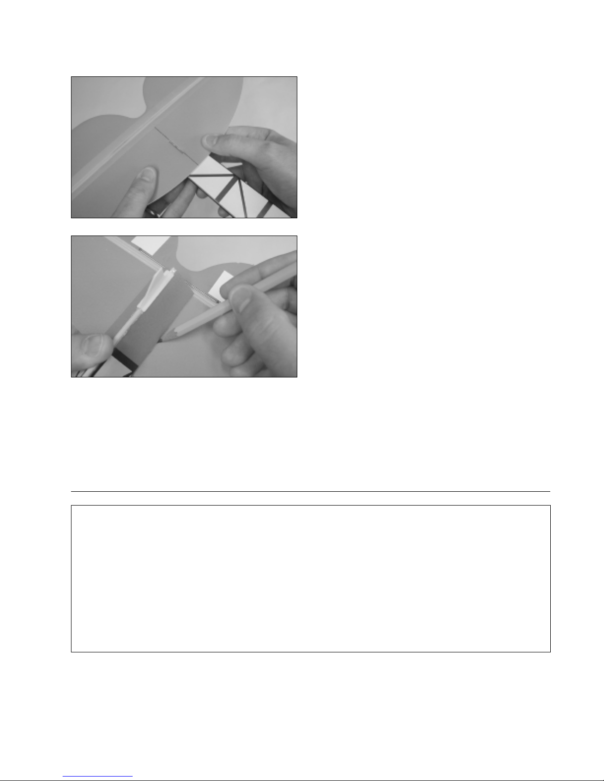
Step 2: Installing the Elevator Joiner Wire
❑After the epoxy has cured, remove the pieces of masking tape and carefully sand the ends of the spar even with the
ends of the stabilizer.
❑Place the prebent wire on the bottom of the elevator.
❑Center the wire over the middle of the elevator, making
sure that the front of the wire is even with the leading edge.
❑When satisfied with the alignment, push the wire down
firmly to make an impression of the wire in the foam.
❑Remove the wire.
❑Using a ruler and a modeling knife, carefully cut a very
shallow groove in the elevator using the impression left in
the foam as a guide.
❑Test-fit the joiner wire into place. It should be flush with the bottom of the elevator and fit firmly in the groove.
❑Mix a small quantity of 5 minute epoxy and carefully glue the joiner wire into place. Remove any excess epoxy
before it sets up using a paper towel and rubbing alcohol.
IMPORTANT
During the drying process, double-check that the leading edge of the elevator stays straight and that the elevator is flat on
your work table.
12 Need help or have any questions? Call us at 1-714-963-0329 or send us an email to [email protected]
❑After the epoxy has cured, carefully apply one piece of
elevatorreinforcementboard overtheendsofthe joinerwire.
IMPORTANT
Make sure each piece covers the end of the joiner wire.
Step 3: Hinging the Elevator
❑Hinge the elevator to the horizontal stabilizer using the
clear decal. Apply the hinge to the top of the parts and make
sure there is a 1/16" gap between them.
☛Use the guide marks on the ends of the hinge decal to
help you set the proper hinge gap.
Step 4: Mounting the Horizontal Stabilizer
❑Using a ruler and a pencil, draw a centerline across
the top of the horizontal stabilizer. The line should be
perpendicular to the hinge line.
❑Using the tip of your modeling knife, remove the die-cut foam piece from the middle of the stabilizer.
❑Using 220 gritsandpaper with asanding block, lightly sand the edgesof the stabilizer and the elevatorsmooth and even
with each other.
❑Using a ruler and a modeling knife, carefully cut out the clear elevator hinge from the decal sheet.
13
Visit our website at http://watt-age.globalhobby.com for information on other Wattage products
❑Kwik Bond 5 Minute Epoxy
❑Excel Modeling Knife
❑Scissors
❑Builder's Triangle
❑220 Grit Sandpaper w/Sanding Block
YOU'LL NEED THE FOLLOWING PARTS:
❑{1} Vertical Stabilizer w/Rudder
SECTION 3: VERTICAL STABILIZER
❑{1} Decal Sheet
YOU'LL NEED THE FOLLOWING SUPPLIES:
❑Paper Towels
❑Rubbing Alcohol
❑NHP Epoxy Mixing Sticks
❑NHP Epoxy Mixing Cups
❑Set the horizontal stabilizer assembly on top of the
fuselage.
❑To align the stabilizer properly, the back edge of the
fiberglass spar should be even with the back edge of the
fuselageand the centerlineyou drew ontop of the stabilizer
should be centered over the middle of the fuselage.
❑When satisfied with the alignment, hold the stabilizer in
place and use a pencil to draw two lines on the bottom of the
stabilizer(one oneachside)whereitmeetsthefuselagesides.
❑Mix a small quantity of 5 minute epoxy and apply a thin layer to only the bottom of the stabilizer between the two
lines you drew.
❑Set the stabilizer back into place and realign it. Remove any excess epoxy using a paper towel and rubbing alcohol,
and hold the stabilizer firmly in place until the epoxy sets up.
Step 1: Hinging the Rudder
❑Carefully remove the die-cut vertical stabilizer and rudder from the foam sheet.
14 Need help or have any questions? Call us at 1-714-963-0329 or send us an email to [email protected]
❑Using the tip of your modeling knife, carefully remove
the piece of die-cut foam from the rudder.
❑Usingapairofscissors,carefullycutouttherightandleftrudderdecalsfromthedecalsheet. Notice that the left-side
decal acts as the rudder hinge, too.
❑Carefully apply the right-side decal onto the rudder. After the decal is in place, use a pair of scissors to trim the decal
flush with the edges of the rudder.
❑Hinge the rudder to the vertical stabilizer using the left
side decal, making sure there is a 1/16" hinge gap between
the two parts.
❑After the decal is in place, use a pair of scissors to trim the decal flush with the edges of the rudder. Once you've
trimmed the decal, use 220 grit sandpaper with a sanding block to lightly sand the edges of the stabilizer and the rudder
smooth and even.
❑Using a modeling knife, cut away and remove the decal from over both sides of the die-cut hole in the rudder.
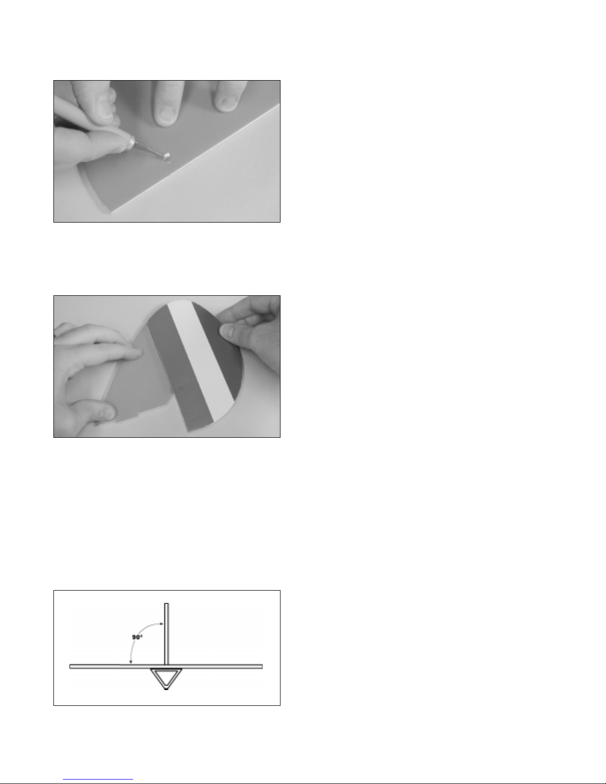
Step 4: Mounting the Vertical Stabilizer
❑Set the vertical stabilizer assembly on top of the horizontal stabilizer. To align it properly, the tab in the vertical
stabilizer should fit into the slot in the horizontal stabilizer and the leading edge of the vertical stabilizer should be even
with the leading edge of the horizontal stabilizer.
❑While holding the vertical stabilizer in place, use a
builder's triangle to check to ensure that it is aligned 90º to
the horizontal stabilizer.

15
Visit our website at http://watt-age.globalhobby.com for information on other Wattage products
❑When satisfied with the alignment, remove the vertical stabilizer.
❑Mix a small quantity of 5 minute epoxy and apply a thin layer to only the bottom edge of the vertical stabilizer.
❑Set the stabilizer back into place and realign it, double-
checking that it is aligned 90º to the horizontal stabilizer.
❑Remove any excess epoxy using a paper towel and
rubbing alcohol, and hold the stabilizer in place until the
epoxy sets up.
❑# 1 Phillips Head Screwdriver
❑Needle Nose Pliers
❑Electric Drill
YOU'LL NEED THE FOLLOWING PARTS:
❑{1} Prebent Main Gear Wire
❑{2} Main Gear Wheels
❑{2} Nylon Wheel Retainers
SECTION 4: MOTOR AND GEAR BOX INSTALLATION
❑{1} 370 Motor w/Gear Box
❑{3} 3mm x 12mm Wood Screws
YOU'LL NEED THE FOLLOWING SUPPLIES:
❑1/16" Drill Bit
❑Pencil
Step 1: Installing the Motor and Gear Box Assembly
❑Carefully press the landing gear wire into the molded
groove in the back of the gear box assembly.
❑Slide the motor wires into the precut hole in the front of the fuselage and push the motor assembly up against the
plywood motor mount.

16 Need help or have any questions? Call us at 1-714-963-0329 or send us an email to [email protected]
❑Align the bottom of the gear box assembly with the
bottom of the motor mount.
❑Use a pencil to mark the locations of the three mounting
holes onto the motor mount.
❑Remove the gear box assembly and set it aside. Using a drill with a 1/16" drill bit, drill pilot holes through the motor
mount at each of the three marks you drew.
❑Set the gear box assembly back into place and realign it.
❑Install and tighten the three 3mm x 12mm wood screws
to hold the gear box assembly securely to the fuselage.
☛Don't overtighten the screws or you might strip the
motor mount.
Step 2: Installing the Wheels
❑Slide one wheel onto one of the axles.
❑Using needle nose pliers, carefully squeeze one nylon
wheel retainer onto the axle to secure the wheel intoplace.
☛Double-check that the wheel spins without binding. If the wheel does bind, carefully pull the retainer just far enough
away from the wheel to prevent the binding.
❑Repeat the procedure above to install the second wheel and wheel retainer.
17
Visit our website at http://watt-age.globalhobby.com for information on other Wattage products
❑Magnum Z-Bend Pliers
❑Wire Cutters
❑Needle Nose Pliers
❑Excel Modeling Knife
YOU'LL NEED THE FOLLOWING PARTS:
❑{2} 1.5mm x 400mm Threaded Pushrod Wires
❑{2} Nylon Control Horns w/Backplates
SECTION 5: ELEVATOR & RUDDER PUSHROD INSTALLATION
❑{2} Nylon Clevises
YOU'LL NEED THE FOLLOWING SUPPLIES:
❑Electric Drill
❑1/16" Drill Bit
❑Ruler
❑Pencil
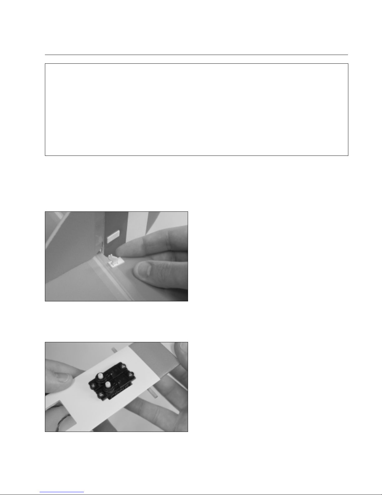
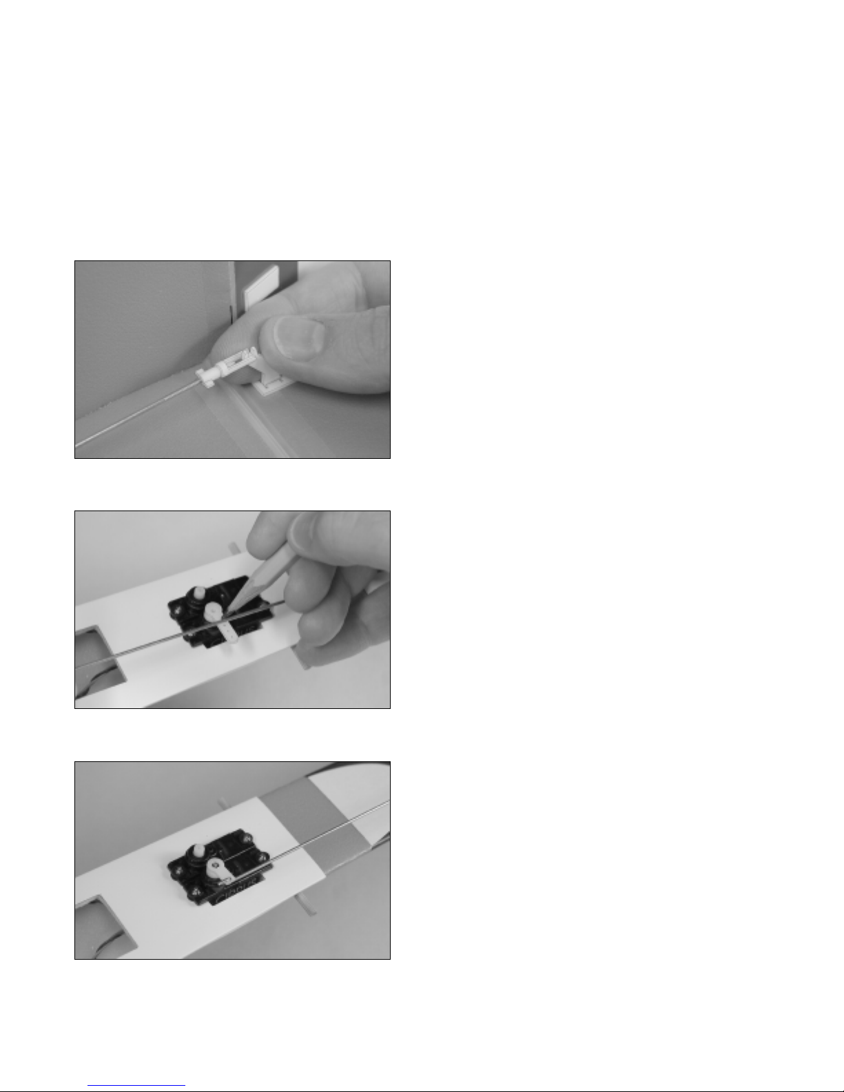
Step 2: Installing the Servos
❑Test fit your two micro servos into the rear hole in the
fuselage. If necessary, use a modeling knife to enlarge the
hole to accommodate your particular servos.
☛Both of the servos' output shafts should face toward the
front of the fuselage.
❑Install the rubber grommets and brass collets onto each of the servo mounting lugs.
❑Mount the servos using the servo mounting screws provided with your servos. To make it easier to install the screws,
use the tip of your modeling knife to make small pilot holes in the reinforcement board.
❑Push one control horn through each die-cut hole in the rudder and the elevator. The tip of the elevator control horn
should face the top of the elevator and the tip of the rudder control horn should face the side opposite the elevator
control horn.
Step 1: Installing the Control Horns
❑Making sure that the flat portion of the backplates face
away from the control surfaces, push the backplates over the
ends of the control horns until you hear them "click" firmly
into place.
18 Need help or have any questions? Call us at 1-714-963-0329 or send us an email to [email protected]
Step 3: Installing the Pushrods
❑Plugtheelevatorandrudder servo leads into theirproperslotsinthereceiver. Plug the ESC lead intothereceiverand
the flight battery into the ESC . Turn on the radio system and center both of the servos using the trim levers on the
transmitter.
❑Thread one nylon clevis onto each of the two 1.5mm x 400mm threaded pushrod wires. Thread the clevises on far
enough to leave room for adjustments later.
❑Carefullysnap the clevison one pushrodinto the elevator
control horn.
❑Withboththeservohornandtheelevatorcentered,usea
pencil to draw a mark on the pushrod wire where it crosses
the hole that is 1/4" out from the center of the servo horn.
❑Placea "single arm"servohorn onto theelevator servo, makingsurethat the servohorn is centeredandpoints toward
the outside of the fuselage. The arm should have at least three holes in it.
❑Using Magnum Z-Bend Pliers, make a Z-Bend in the pushrod wire at the mark you drew. Use wire cutters to remove
the excess wire.
❑Remove the servo horn, attach it to the Z-Bend, then
attachthe servo horn totheservo, making sureit'scentered.
Install and tighten the servo horn retaining screw, provided
with your servo, to secure the servo horn into place.
☛You will need to enlarge the hole in the servo arm using
a 1/16" drill bit, so that the pushrod wire will fit through.

19
Visit our website at http://watt-age.globalhobby.com for information on other Wattage products
❑Installtherudderpushrodwireusingthe same technique
as with the elevator pushrod wire. The Z-Bend should be
installed into the hole that is 1/4" out from the center of the
servo horn as well.
❑Double-check that the elevator and rudder are still cen-
tered. If they are out of adjustment, remove the clevises and
readjust them until you are satisfied with the alignment.
Unplug and turn off your radio system.
YOU'LL NEED THE FOLLOWING PARTS:
❑{1} Left Wing Panel
❑{1} Right Wing Panel
❑{1} Molded Plastic Wing Mount
SECTION 6: WING ASSEMBLY
❑{1} Wing Reinforcement Board - 2 Parts
❑{2} 180mm Long Adhesive Strips
YOU'LL NEED THE FOLLOWING SUPPLIES:
Step 1: Joining the Wing Panels
❑After the epoxy has cured, apply one piece of adhesive
tape on the bottom of the wing, over the center section joint.
❑Turn the wing over and apply the second piece of adhe-
sive tape on the top of the wing, over the center section joint.
IMPORTANT
The top piece should overlap both the leading edge and the
trailing edge.
❑Kwik Bond 5 Minute Epoxy
❑Excel Modeling Knife
❑Ruler
❑Pencil
❑Masking Tape
❑220 Grit Sandpaper w/Sanding Block
❑Paper Towels
❑Rubbing Alcohol
❑NHP Epoxy Mixing Sticks
❑NHP Epoxy Mixing Cups
❑Hair Dryer
❑Test-fit thetwowingpanelstogether. Thereshouldbenogapsinthe center section jointandthetopandbottomofthe
wing panels should be perfectly flat.
❑When satisfied with the alignment, glue the wing panels together using a generous amount of 5 minute epoxy.
Remove any excess epoxy before it sets up and hold the wing panels firmly in place until the epoxy dries.
20 Need help or have any questions? Call us at 1-714-963-0329 or send us an email to [email protected]
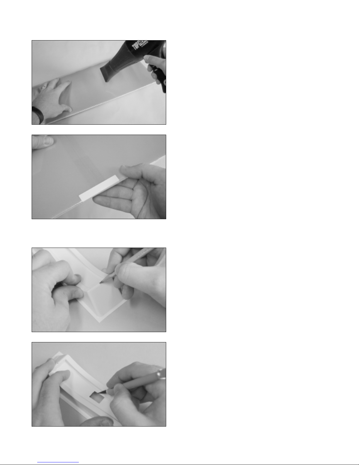
❑Withtheadhesivetapesecurelyinplace,useahairdryer
toshrinktheheat-shrinkmaterialtightacrosstheentirewing,
both top and bottom.
WARNING
Work slowly and use only enough heat to shrink the heat-
shrink material. Excessive heat could melt the foam wing.
❑Carefully apply the leading and trailing edge pieces of
reinforcementboardtothewingmakingsurethey'recentered
overthecenterline. Noticethatthe pieces are scored tomake
it easier to bend around the wing.
IMPORTANT
The middle portion of one piece of reinforcement board is
thinner than the other piece. The piece with the thinner
center section is for the leading edge.
Step 2: Installing the Plastic Wing Mount
❑Using a ruler and a pencil, measure and draw a center-
line on top of the wing mount, at both the front and the back.
❑Using a modeling knife, carefully cut a hole in the wing
mount using the factory-made scribe lines as a guide.
☛This hole will allow the aileron servo lead(s) to pass
through.
Table of contents
Popular Tools manuals by other brands


Hitachi Koki
Hitachi Koki H 60MA Handling instructions

Topeak
Topeak TORQ STICK 4-20Nm quick start guide

Signode
Signode TENSION-WELD VXT2-19 Operation, parts and safety manual

MG
MG MERO 18 P operating instructions

Northern Industrial Tools
Northern Industrial Tools 159451 owner's manual

Rockler
Rockler 52149 manual