Watts tekmar 294EXP User manual
Installation, Operation and Maintenance Manual
Smart Boiler Expansion 294EXP
IOM-T-294EXP
WARNING
!
Please read carefully before proceeding with
installation. Your failure to follow any attached
instructions or operating parameters may lead to the
product’s failure.
Keep this Manual for future reference.

2IOM-T-294EXP 2214 © 2022 tekmar
Important Safety Information .........................3
Radio Frequency Statement .........................4
Installation .......................................5
Installation Location .............................5
Wiring Schematic ...............................6
Wiring Instructions ..............................7
User Interface ....................................9
Status Icons ...................................9
Labels for Boilers 9 to 12 or 13 to 16 ................9
Sequence of Operation ............................10
DIP Switches .................................10
Power On LED ................................10
Communication LED ............................10
Boiler Output Operation .........................10
Troubleshooting..................................11
Technical Data ...................................12
Limited Warranty & Product Return Procedure...........12
Table of Contents
IOM-T-294EXP 2214 © 2022 tekmar 3
This is a safety-alert symbol. The safety alert sym-
bol is shown alone or used with a signal word
(DANGER, WARNING, or CAUTION), a pictorial
and/or a safety message to identify hazards.
When you see this symbol alone or with a signal
word on your equipment or in this Manual, be alert
to the potential for death or serious personal injury.
• It is the installer's responsibility to ensure that this control
is safely installed according to all applicable codes and
standards.
• Improper installation and operation of this control could
result in damage to the equipment and possibly even
personal injury or death.
• This control is not intended for use as a primary limit
control. Other controls that are intended and certified as
safety limits must be placed into the control circuit.
Do not attempt to service the control. There are no user
serviceable parts inside the control. Attempting to do so
voids warranty.
To avoid serious personal injury and damage to the equipment:
It is your responsibility to ensure that this control is safely
installed according to all applicable codes and standards.
tekmar®is not responsible for damages resulting from
improper installation and/or maintenance.
• Read Manual and all product labels BEFORE
using the equipment. Do not use unless you
know the safe and proper operation of this
equipment.
• Keep this Manual available for easy access by
all users.
• Replacement Manuals are available at
tekmarControls.com
Important Safety Information
This pictorial alerts you to electricity, electrocution,
and shock hazards.
Double insulated.
This symbol identifies hazards which, if not
avoided, could result in death or serious injury.
This symbol identifies hazards which, if not
avoided, could result in minor or moderate
injury.
This symbol identifies practices, actions, or
failure to act which could result in property
damage or damage to the equipment.

4IOM-T-294EXP 2214 © 2022 tekmar
This equipment has been tested and found to comply with the limits for a Class A digital device, pursuant to part 15 of the FCC
Rules. These limits are designed to provide reasonable protection against harmful interference when the equipment is operated in
a commercial environment. This equipment generates, uses, and can radiate radio frequency energy and, if not installed and used
in accordance with the instruction manual, may cause harmful interference to radio communications. Operation of this equipment
in a residential area is likely to cause harmful interference in which case the user will be required to correct the interference at his
own expense.
This device complies with part 15 of the FCC Rules and with Industry Canada license-exempt RSS standard(s). Operation is
subject to the following two conditions: (1) this device may not cause harmful interference, and (2) this device must accept any
interference received, including interference that may cause undesired operation.
The antenna used for this radio must be properly installed and maintained and must provide a separation distance of at least
7.9 inches (20 cm) from all persons.
Changes or modifications not expressly approved by the party responsible for compliance could void the user’s authority to
operate the equipment.
Le présent appareil est conforme aux CNR d’Industrie Canada applicables aux appareils radio exempts de license. L’exploitation
est autorisée aux deux conditions suivantes:
(1) l’appareil ne doit pas produire de brouillage, et
(2) l’utilisateur de l’appareil doit accepter tout brouillage radioélectrique subi, même si le brouillage est susceptible d’en compromettre
le fonctionnement.
Radio Frequency Statement

IOM-T-294EXP 2214 © 2022 tekmar 5
Use a Phillips screwdriver to remove
the two screws on the cover.
Pull the front cover towards you. The
top of the cover will pivot on a hinge.
Remove the cover by releasing the
pivot hooks.
Mount the enclosure to a wall using
#6 wood screws in the four mounting
holes. Use screw anchors if drilling
into masonry.
Use the 24 knock-outs to install
connecting conduits and cabling to
the control.
To install the cover, hook the top
of the cover to the enclosure, then
pivot the bottom to shut.
Use a Phillips screwdriver to fasten
the two bottom screws.
When choosing the location for the control, consider the following:
• Keep dry. Avoid potential leakage onto the control.
RH 90% to 104°F (40°C).
Non-condensing environment.
• Do not expose to operating temperatures beyond 32-104°F
(0-40°C)
• Provide adequate ventilation.
• Keep away from equipment, appliances or other sources of
electrical interference.
• Provide easy access for wiring, viewing, & adjusting the
display screen.
• Mount approximately 5 ft. (1.5 m) off the finished floor.
• Locate the control near pumps &/or zone valves if possible.
• Provide a solid backing to mount the enclosure to. For
example: plywood, studs, etc
• Use the conduit knockouts provided on the upper, lower,
back & sides of the enclosure.
Installation
Installation Location
6IOM-T-294EXP 2214 © 2022 tekmar
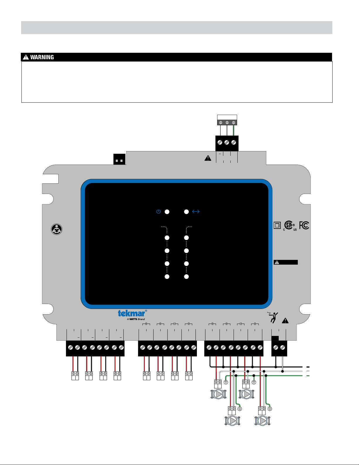
This section provides a wiring schematic for the control.
Wiring Schematic
• Before wiring, ensure all power is turned off and take all
necessary precautions.
• Strip all wiring to a length of 3⁄8in. or 10 mm for all terminals.
• A circuit breaker or power disconnect that provides power
to the control should be located nearby & clearly labeled.
• Refer to the current and voltage ratings at the back of this
brochure before connecting devices to this control.
• Only qualified personnel should install or service the control.
CAN ICES-3 (A)/NMB-3(A)
Class 2 Circuits
Boiler Mod:
Class 2 Circuits
Input Power:
115 V (ac) ±10%, 60 Hz, 6 W
Relays:
230 V (ac), 5 A, 1/3 hp
Operating Temperature:
32°F to 122°F (0°C to 50°C)
Use Copper Conductors Only
H2062B
76
Boiler 6
54
Boiler 5
Mod
98
Boiler 7
1110
Boiler 8
1312
Boiler 5
Enable
1514
Boiler 6
Enable
1716
Boiler 7
Enable
1918
Boiler 8
Enable
2120
Boiler 5
Pump/Vlv
2322
Boiler 6
Pump/Vlv
2524
Boiler 7
Pump/Vlv
2726
Boiler 8
Pump/Vlv
2928
Power
N
To Reduce the Risk of Electric
Shock - Do not connect to a
circuit operating at more than
150 volts to ground.
Pour réduire les risques
d'électrocution choc - ne pas
raccorder à un circuit
fonctionnant à plus de 150 V à
la terre.
L
231
+Gnd
Expansion
Expansion 5 to 8
Set switches: 1 to Off, 2 to Off
+Mod
+Mod
+Mod
+
Smart Boiler Expansion 294EXP
For product literature:
Pour la documentation
du produit:
Watts.com/tekmar
tektra 1152-01
Designed and assembled
in Canada
DANGER
5
6
7
8
5
6
7
8
Boiler Pump/Valve
Boiler Expansion 5 to 8
N
G
L
LNG LNG
LNG LNG
+-+-+-+-TT TT TT TT
-+Gnd

IOM-T-294EXP 2214 © 2022 tekmar 7
Modulating Boilers (Terminals 4 to 11)
The control provides either a 0-10 V (dc) or a 4-20 mA output to each boiler. Polarity is important.
• Connect the control Mod (+) terminals 4, 6, 8, 10 to boilers 5, 6, 7 and 8 analog signal input (+)
respectively.
• Connect the control Mod (-) terminals 5, 7, 9, 11 to boilers 5, 6, 7 and 8 analog signal input (-)
respectively.
Some modulating boilers may also require a boiler on/off enable signal in addition to the
modulating signal. Please consult the boiler manual.
Modutrol IV
tekmar
B
R
W
+
-
tekmar
V9055
+
-
B
R
W
Modutrol IV™
0 - 135 Ω
Actuating
Motor
B
R
W
Mod +
-
Modutrol IV
tekmar
B
R
W
+
-
tekmar
V9055
+
-
B
R
W
B
R
W
V9055™
0 - 135 Ω
Actuating
Motor
Mod +
-
The 4 to 20 mA output can be converted to a 0 - 135 Ω
output for a Modutrol IV™ gas valve actuating motor using a
0 - 135 Ω tekmar Converter 005 (sold separately).
The 4 to 20 mA output can be converted to a 0 - 135 Ω
output for a V9055™ gas valve actuating motor using a
0 - 135 Ω tekmar Converter 005 (sold separately).
Boiler
Control
294
Boiler
Control
294
Modutrol IV™ and V9055™ are trademarks of Honeywell, Inc.
Boiler Enable (Terminals 12 to 19)
A single stage condensing or non-condensing boiler is enabled through the TT contacts.
• For Boiler 5 connect the Boiler Enable terminals 12 and 13 to the boiler TT contacts.
• For Boiler 6 connect the Boiler Enable terminals 14 and 15 to the boiler TT contacts.
• For Boiler 7 connect the Boiler Enable terminals 16 and 17 to the boiler TT contacts.
• For Boiler 8 connect the Boiler Enable terminals 18 and 19 to the boiler TT contacts.
Boiler Expansion (Terminals 1, 2, 3)
The control operates 4 on board boilers and is expandable in groups of 4 up to a
maximum of 16 through the use of boiler expansions. The control connects to the
expansion through a wired three-wire connection. The maximum bus cable length is
100 feet (30 m) using 18 AWG solid conductor cable.
• Connect the 294 terminal 18 (-) to the 294EXP terminal 1 (-).
• Connect the 294 terminal 19 (+) to the 294EXP terminal 2 (+).
• Connect the 294 terminal 20 (Gnd) to the 294EXP terminal 3 (Gnd). 18 19 20
Gnd
-+
Expansion
123
Gnd
-+
Expansion
This section explains how to wire individual devices to the Smart Boiler Expansion 294EXP.
Wiring Instructions

8IOM-T-294EXP 2214 © 2022 tekmar
Boiler Pump / Valve (Terminals 20 to 27)
Boiler pumps or valves requiring up to 230 V (ac) 5 A, 1/3 hp can be switched through terminals 20
to 27. If a single power source is used for multiple pumps, ensure they are not tied together at any
point between the pumps and the control. For simplicity in wiring and troubleshooting, a separate
breaker for each pump is recommended.
For pumps:
•
Connect the power source line wire (L) to terminal 20.
• Connect a wire from terminal 21 to the pump Line In terminal.
• Connect the pump Neutral (N) to the power source neutral.
• Repeat for additional boiler pumps 6 (terminals 22, 23), boiler pump 7 (24, 25) and boiler pump
8 (terminals 26, 27).
• Ensure each pump is connected to earth ground.
N
G
L
L
NG
Ground
Boiler 1
20 21
Pump/Valve
C
R
R
C
Boiler 1
20 21
Pump/V
alve
For 120 V (ac) valves:
•
Connect the power source line wire (L) to terminal 20.
• Connect a wire from terminal 21 to the valve Line In terminal.
• Connect the valve Neutral (N) to the power source neutral.
• Repeat for additional valves 6 (terminals 22, 23), valve 7 (24, 25) and valve 8 (terminals 26, 27).
• Ensure each pump is connected to earth ground.
For 24 V (ac) valves:
• Connect the power source Red wire (R) to terminal 20.
• Connect a wire from terminal 21 to the valve power terminal.
• Connect the valve power common to the power source common (C).
• Repeat for additional boiler valves 6 (terminals 22, 23), boiler valve 7 (24, 25) and boiler valve
8 (terminals 26, 27).
N
G
L
L
NG
Ground
Boiler 1
20 21
Pump/Valve
Provide a 15 Amp circuit for the input power.
• Connect the 115 V (ac) line wire (L) to terminal 28.
• Connect the neutral wire (N) to terminal 29.
Input Power (Terminals 28, 29)
N
L
Power In
LN
28 29

IOM-T-294EXP 2214 © 2022 tekmar 9
POWER
LED is on when powered.
COMMUNICATION
LED is on when communicating to 294.
5
6
7
8
5
6
7
8
Boiler Pump/Valve
Boiler Expansion 5 to 8
Status Icons
User Interface
Labels for Boilers 9 to 12 or 13 to 16
The 294EXP is assembled from the factory with labels to operate boilers 5 through 8. Included in the packaging are labels for
boilers 9 to 12 and another set for boilers 13 to 16. If operating one of these boiler groups, locate the correct label, peel the label
from the backing, and using the plastic oval shape as a guide, apply the label to on top of the existing label.
CAN ICES-3 (A)/NMB-3(A)
Class 2 Circuits
Boiler Mod:
Class 2 Circuits
Input Power:
115 V (ac) ±10%, 60 Hz, 6 W
Relays:
230 V (ac), 5 A, 1/3 hp
Operating Temperature:
32°F to 122°F (0°C to 50°C)
Use Copper Conductors Only
H2062B
76
Boiler 6
54
Boiler 5
Mod
98
Boiler 7
1110
Boiler 8
1312
Boiler 5
Enable
1514
Boiler 6
Enable
1716
Boiler 7
Enable
1918
Boiler 8
Enable
2120
Boiler 5
Pump/Vlv
2322
Boiler 6
Pump/Vlv
2524
Boiler 7
Pump/Vlv
2726
Boiler 8
Pump/Vlv
2928
Power
N
To Reduce the Risk of Electric
Shock - Do not connect to a
circuit operating at more than
150 volts to ground.
Pour réduire les risques
d'électrocution choc - ne pas
raccorder à un circuit
fonctionnant à plus de 150 V à
la terre.
L
231
+Gnd
Expansion
Expansion 5 to 8
Set switches: 1 to Off, 2 to Off
+Mod
+Mod
+Mod
+
Smart Boiler Expansion 294EXP
For product literature:
Pour la documentation
du produit:
Watts.com/tekmar
tektra 1152-01
Designed and assembled
in Canada
DANGER
CAN ICES-3 (A)/NMB-3(A)
Class 2 Circuits
Boiler Mod:
Class 2 Circuits
Input Power:
115 V (ac) ±10%, 60 Hz, 6 W
Relays:
230 V (ac), 5 A, 1/3 hp
Operating Temperature:
32°F to 122°F (0°C to 50°C)
Use Copper Conductors Only
H2063B
76
Boiler 10
54
Boiler 9
Mod
98
Boiler 11
1110
Boiler 12
1312
Boiler 9
Enable
1514
Boiler 10
Enable
1716
Boiler 11
Enable
1918
Boiler 12
Enable
2120
Boiler 9
Pump/Vlv
2322
Boiler 10
Pump/Vlv
2524
Boiler 11
Pump/Vlv
2726
Boiler 12
Pump/Vlv
2928
Power
N
To Reduce the Risk of Electric
Shock - Do not connect to a
circuit operating at more than
150 volts to ground.
Pour réduire les risques
d'électrocution choc - ne pas
raccorder à un circuit
fonctionnant à plus de 150 V à
la terre.
L
231
+Gnd
Expansion
Expansion 9 to 12
Set switches: 1 to On, 2 to Off
+Mod
+Mod
+Mod
+
Smart Boiler Expansion 294EXP
For product literature:
Pour la documentation
du produit:
Watts.com/tekmar
tektra 1152-01
Designed and assembled
in Canada
DANGER
5
6
7
8
5
6
7
8
Boiler Pump/Valve
Boiler Expansion 5 to 8
9
10
11
12
9
10
11
12
Boiler Pump/Valve
Boiler Expansion 9 to 12
10 IOM-T-294EXP 2214 © 2022 tekmar
The power LED operates as follows.
LED Operation
On Power applied and control is operating correctly
Off No power or the control is faulty
When powered on, the Smart Boiler Expansion 294EXP communicates to the Smart Boiler Control 294. The communication LED
operates as follows.
LED Operation
On Communication with 294
Off No communication with 294
All boiler relays are normally off and the modulating outputs at 0 V (dc) or 4 mA. The Smart Boiler Control 294EXP responds to
commands from the 294 to turn on a boiler, the modulating signal, and the boiler pump or valve. The status on the 294EXP
display will match the 294 Boiler Status menu.
Output LED Operation
Boiler 5, 9, 13 On Boiler enable 5, 9, 13 relay is closed
Off Boiler enable 5, 9, 13 relay is open
Boiler 6, 10, 14 On Boiler enable 6, 10, 14 relay is closed
Off Boiler enable 6, 10, 14 relay is open
Boiler 7, 11, 15 On Boiler enable 7, 11, 15 relay is closed
Off Boiler enable 7, 11, 15 relay is open
Boiler 8, 12, 16 On Boiler enable 8, 12, 16 relay is closed
Off Boiler enable 8, 12, 16 relay is open
Boiler Pump/Valve 5, 9, 13 On Boiler pump/valve 5, 9, 13 relay is closed
Off Boiler pump/valve 5, 9, 13 relay is open
Boiler Pump/Valve 6, 10, 14 On Boiler pump/valve 6, 10, 14 relay is closed
Off Boiler pump/valve 6, 10, 14 relay is open
Boiler Pump/Valve 7, 11, 15 On Boiler pump/valve 7, 11, 15 relay is closed
Off Boiler pump/valve 7, 11, 15 relay is open
Boiler Pump/Valve 8, 12, 16 On Boiler pump/valve 8, 12, 16 relay is closed
Off Boiler pump/valve 8, 12, 16 relay is open
Two DIP switches located on the top left side of the control. The DIP switch positions determine the boiler groups that the Smart
Boiler Expansion 294EXP operates.
Boilers DIP Switch 1 DIP Switch 2
5 to 8 Off Off
9 to 12 On Off
13 to 16 Off On
Sequence of Operation
Power On LED
Communication LED
Boiler Output Operation
DIP Switches

IOM-T-294EXP 2214 © 2022 tekmar 11
Symptom Description
Power LED Off
Using an electrical meter, check that the supply voltage is between 103.5 and 126.5 V (ac). If the supply voltage
is correct and the Power LED remains off the control may be faulty.
Communication LED
Off
Check that the boiler expansion on wiring terminals 1, 2, and 3 are connected using 3-conductor 18 AWG LVT
wire if connections are less than 100 feet (30 m). Connections exceeding 100 feet (30 m) or installed in high
radio-frequency environments should use 3-conductor, 22 AWG shielded-twisted pair. The boiler expansion
wiring is polarity sensitive so it is important to check that the wire color codes are in the correct terminal locations.
Troubleshooting

Limited Warranty The liability of tekmar under this warranty is
limited. The Purchaser, by taking receipt of any tekmar product
(“Product”), acknowledges the terms of the Limited Warranty in
effect at the time of such Product sale & acknowledges that it has
read & understands same.
The tekmar Limited Warranty to the Purchaser on the Products sold
hereunder is a manufacturer’s pass-through warranty which the
Purchaser is authorized to pass through to its customers. Under the
Limited Warranty, each tekmar Product is warranted against defects
in workmanship & materials if the Product is installed & used in
compliance with tekmar’s instructions, ordinary wear & tear except-
ed. The pass-through warranty period is for a period of twenty-four
(24) months from the production date if the Product is not installed
during that period, or twelve (12) months from the documented date
of installation if installed within twenty-four (24) months from the
production date.
The liability of tekmar under the Limited Warranty shall be limited to, at tek-
mar’s sole discretion: the cost of parts & labor provided by tekmar to repair
defects in materials &/or workmanship of the defective product; or to the
exchange of the defective product for a warranty replacement product; or
to the granting of credit limited to the original cost of the defective product,
& such repair, exchange or credit shall be the sole remedy available from
tekmar, &, without limiting the foregoing in any way, tekmar is not respon-
sible, in contract, tort or strict product liability, for any other losses, costs,
expenses, inconveniences, or damages, whether direct, indirect, special,
secondary, incidental or consequential, arising from ownership or use of the
product, or from defects in workmanship or materials, including any liability
for fundamental breach of contract.
The pass-through Limited Warranty applies only to those defective Products
returned to tekmar during the warranty period. This Limited Warranty does
not cover the cost of the parts or labor to remove or transport the defec-
tive Product, or to reinstall the repaired or replacement Product, all such
costs & expenses being subject to Purchaser’s agreement & warranty with
its customers.
Any representations or warranties about the Products made by Purchaser
to its customers which are different from or in excess of the tekmar Limited
Warranty are the Purchaser’s sole responsibility & obligation. Purchaser shall
indemnify & hold tekmar harmless from & against any & all claims, liabilities &
damages of any kind or nature which arise out of or are related to any such
representations or warranties by Purchaser to its customers.
The pass-through Limited Warranty does not apply if the returned Product
has been damaged by negligence by persons other than tekmar, accident,
fire, Act of God, abuse or misuse; or has been damaged by modifications,
alterations or attachments made subsequent to purchase which have not
been authorized by tekmar; or if the Product was not installed in compliance
with tekmar’s instructions &/or the local codes & ordinances; or if due to
defective installation of the Product; or if the Product was not used in com-
pliance with tekmar’s instructions.
THIS WARRANTY IS IN LIEU OF ALL OTHER WARRANTIES, EXPRESS
OR IMPLIED, WHICH THE GOVERNING LAW ALLOWS PARTIES TO
CONTRACTUALLY EXCLUDE, INCLUDING, WITHOUT LIMITATION, IMPLIED
WARRANTIES OF MERCHANTABILITY & FITNESS FOR A PARTICULAR
PURPOSE, DURABILITY OR DESCRIPTION OF THE PRODUCT, ITS NON-
INFRINGEMENT OF ANY RELEVANT PATENTS OR TRADEMARKS, &
ITS COMPLIANCE WITH OR NON-VIOLATION OF ANY APPLICABLE
ENVIRONMENTAL, HEALTH OR SAFETY LEGISLATION; THE TERM OF
ANY OTHER WARRANTY NOT HEREBY CONTRACTUALLY EXCLUDED IS
LIMITED SUCH THAT IT SHALL NOT EXTEND BEYOND TWENTY-FOUR (24)
MONTHS FROM THE PRODUCTION DATE, TO THE EXTENT THAT SUCH
LIMITATION IS ALLOWED BY THE GOVERNING LAW.
Product Warranty Return Procedure All Products that are believed to
have defects in workmanship or materials must be returned, together with a
written description of the defect, to the tekmar Representative assigned to
the territory in which such Product is located. If tekmar receives an inquiry
from someone other than a tekmar Representative, including an inquiry
from Purchaser (if not a tekmar Representative) or Purchaser’s customers,
regarding a potential warranty claim, tekmar’s sole obligation shall be to
provide the address & other contact information regarding the appropriate
Representative.
Limited Warranty and Product Return Procedure
IOM-T-294EXP 2214 © 2022 tekmar
Tel: 1-800-438-3903 • Fax: (250) 984-0815
tekmarControls.com
All specifications are subject to change without notice
Smart Boiler Control 294
Literature Submittal, Installation and Operating Manual
Packaged weight 2.4 lb. (1100 g)
Dimensions 9" H x 8" W x 211⁄16" D (229 x 203 x 60 mm)
Enclosure Blue ABS plastic, NEMA type 1
Approvals CSA C US, FCC Part 15B, ICES-003 Class A
Ambient conditions Indoor use only, 32 to 122°F (0 to 50°C), < 90% RH non-condensing, Altitude < 6560 feet (2000 m), Installation Category II,
Pollution Degree 2
Power supply 115 V (ac) ±10%, 60 Hz, 6 W
Relays 230 V (ac), 5 A, 1/3 hp
Modulating outputs 0-10 V (dc) 500 Ω minimum load impedance or 4-20 mA 1 kΩ max load impedance
Technical Data
Table of contents


