IBC P-153B Guide

P-153B NG Burner Kit Replacement
IBC Technologies Inc. 1-844-432-8422 |www.ibcboiler.com
120-388E0 January 09, 2023 Released Document 1 of 7
Instructions for SL 20-115G1/G2
Warning
Improper installation, adjustment, alteration, service or maintenance can cause property damage,
personal injury, or loss of life. Read and understand the entire manual before attempting installation,
start-up, operation, or service. Installation and service must be performed only by an experienced,
skilled installer or service agency.
Failure to follow all instructions in the proper order can cause personal injury or death. Read all
instructions, including all those contained in component manufacturers’ manuals before installing,
starting up, operating, maintaining, or servicing the appliance.
Warning
The IBC heat exchanger has a small amount of combustion chamber insulation (refractory), which
contains ceramic fibers. When exposed to extremely high temperatures, the ceramic fibers that
contain crystalline silica can be converted into cristobalite, classified as a possible human
carcinogen. Avoid disturbing or damaging the refractory.
If damage occurs, contact the factory for directions. Avoid breathing and contact with skin and eyes
and follow these precautions:
1. For conditions of frequent use or heavy exposure, respirator protection is required. Refer to
the “NIOSH Guide to the Selection and Use of Particulate Respirators Certified under 42
CFR 84” for selection and use of respirators certified by NIOSH. For the most current
information, NIOSH can be contacted at 1-800-356-4676 or on the web at
www.cdc.gov/niosh.
2. Wear long sleeved, loose fitting clothing, gloves and eyes protection.
3. Assure adequate ventilation.
4. Wash with soap and water after contact.
5. Wash potentially contaminated clothes separately from other laundry and rinse washing
machine thoroughly.
6. Discard used insulation in an air-tight plastic bag. NIOSH stated first aid: Eye contact -
Irrigate and wash immediately. Breathing - Provide fresh air

IBC Technologies Inc. 1-844-432-8422 |www.ibcboiler.com
120-388E0 January 09, 2023 Released Document 2 of 7
Note
This P-153B burner kit is for use with natural gas only. For propane gas applications, use P-154B.
Propane burner (P-154B)
Natural gas burner (P-153B)
Note
This kit is a revision of a previously existing kit. The letter after the P-kit number indicates the kit
version. For example, P-###Bwould be an earlier version of P-###C.
The instructions and contents listed here are for the latest revision of this kit. Previous versions
may not be suitable for all listed boiler models. Please contact your local IBCdistributor for more
information.
When you purchase this kit from a wholesaler, you'll receive:
Burner Kit, NG - SL 115 G1/G2
Part # Description Quantity
180-038 Burner 1
250-193 Burner gasket 1
150-166 Screws M4x6 3

IBC Technologies Inc. 1-844-432-8422 |www.ibcboiler.com
120-388E0 January 09, 2023 Released Document 3 of 7
Boiler parts diagram
SL20-115 G1 SL20-115 G2
A Fan
B Gas valve
C Gas supply line
D Fan gasket
E Ignitor
F Heat exchanger lid
G Burner gasket
H Heat exchanger lid gasket
I Burner
J Refractory
K Heat exchanger

IBC Technologies Inc. 1-844-432-8422 |www.ibcboiler.com
120-388E0 January 09, 2023 Released Document 4 of 7
Note
A ladder or step may be required to have a clear vertical view of the work area. Do not attempt to
remove the assemblies without a clear view, as damage to the connectors, screws or refractory
may occur.
Burner removal
Preparing the boiler for service
1. Remove call(s) for heat.
2. Remove power to the boiler at a wall switch or a breaker.
3. Shut off gas supply to the boiler.
Do not drain the boiler unless freezing conditions are expected during this procedure.
4. Allow the boiler to cool down to the ambient temperature.
5. Remove the front cover.
6. Remove the top service panel by removing the three yellow thumbscrews at the top corners of the
boiler.
Removing the fan and gas valve assembly
1. Disconnect the two electrical connectors from the fan (A).
2. Disconnect the electrical connector from the gas valve (B).
3. Position the wiring harnesses out of the way of the heat exchanger lid (F).
4. Disconnect the flare-fitting nut on the gas supply line (C).
5. Remove the four 8 mm hex bolts attaching the fan to the heat exchanger lid.
6. Remove the fan and gas valve assembly. Retain the fan gasket (D)(and fan coupler and coupler
gasket for the G1) for reinstallation.
Note
SL20-115 G2 only: The fan and venturi are one unit and must not be separated.
If necessary, the gas valve can be removed from the fan/venturi assembly by removing the two
Torx 25 screws. Retain the gasket between the gas valve and venturi for reinstallation, and
ensure that it is intact and free from debris. For LP models there will be a brass orifice installed in
the gasket. There is no orifice required for NG models.

IBC Technologies Inc. 1-844-432-8422 |www.ibcboiler.com
120-388E0 January 09, 2023 Released Document 5 of 7
Removing the heat exchanger lid
1. Disconnect the ignitor cable (E) and move it out of the way.
2. Remove the two #2 Phillips screws securing the ignitor to the heat exchanger lid.
3. Carefully remove the ignitor by sliding it straight up.
4. Remove the ignitor gasket.
5. Place the ignitor parts on a clean, dry area for reinstallation.
6. Remove the nuts attaching heat exchanger lid to the heat exchanger (K) with a 10 mm wrench or
socket.
7. Mark the alignment between the lid, lid gasket (H) and heat exchanger with a permanent marker or
equivalent.
Caution
Position yourself directly above the heat exchanger lid before removal to ensure a
straight, vertical extraction. Failure to do so may result in refractory damage.
8. Slowly lift the lid-burner assembly (F,I) off the heat exchanger. The refractory (J) should remain in
place in the heat exchanger's combustion chamber shoulder. There is less than 1/8” (3 mm) of
clearance between the burner walls and the refractory; ensure that there is minimal contact between
them to prevent the refractory from cracking.
9. Place the lid with the burner attached on a clean, dry surface.
Removing the burner from the heat exchanger lid
1. Mark the refractory, with a permanent marker or equivalent, so that it lines up with the same mark
made earlier between the lid and heat exchanger.
2. Carefully remove the refractory and place in a clean dry area. (See warning above regarding the
refractory).
3. Gradually loosen and remove the 3 screws securing the burner to the heat exchanger lid, with a #2
Phillips screwdriver.
4. Remove the burner (I).
5. Remove and discard the old burner gasket (G).
Note
SL20-115 G1 only
If present, remove the attached intakeport from the underside of
the heat exchanger lid.
Remove the two set-screws from the fan coupler, and discard.
This part not required for the new burner.
SL20-115 G1
Intake Port

IBC Technologies Inc. 1-844-432-8422 |www.ibcboiler.com
120-388E0 January 09, 2023 Released Document 6 of 7
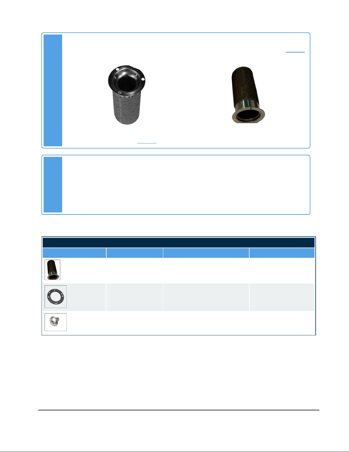
Burner installation
Attaching the burner to the heat exchanger lid
1. Place the heat exchanger lid on a flat surface.
2. Position the burner gasket on the lid, aligning it with the screw holes.
3. Install the new burner in place:
a. Use the three M4 x 6 mm screws to secure the burner and gasket onto the new heat exchanger
lid.
b. Tighten the screws gradually by hand, plus an additional one-eighth (⅛) turn in a cross pattern.
Do not over-tighten.
4. Inspect the refractory for cracks, degradation and flatness. If in doubt, replace with a new one. (See
warning above regarding the refractory).
5. Carefully insert the refractory into the heat exchanger combustion chamber, using the alignment marks
for proper positioning.
6. Ensure that the orange heat exchanger lid gasket is in good condition, flat, and free of debris.
Reinstalling the burner and heat exchanger lid assembly
1. Carefully insert the lid-burner assembly straight down, ensuring that:
There is limited contact between the burner and refractory
The markings made previously on the lid, lid gasket, heat exchanger, and refractory are aligned.
2. Attach the heat exchanger lid and burner assembly onto the new heat exchanger with the six hex nuts
and perform the following:
a. Tighten nuts by hand in a cross pattern, similar to how the burner was tightened
b. Tighten an extra ½ to 1 turn.
Caution
Over-tightening will warp the heat exchanger lid and lid gasket, allowing fumes or
flames to leak.
3. Re-install the ignitor:
a. Position the ignitor gasket on the heat exchanger lid, aligning it with the screw holes.
b. Carefully insert the ignitor into the heat exchanger assembly by sliding it straight down.
c. Tighten the two #2 Phillips screws screws by hand, then an extra ⅛ turn.
4. Reconnect the following cables:
The ignitor cable
The gas valve cable
The two electrical connectors to the fan.

IBC Technologies Inc. 1-844-432-8422 |www.ibcboiler.com
120-388E0 January 09, 2023 Released Document 7 of 7
5. Reinstall the fan-gas valve assembly by following the above steps backwards from Removing the fan
and gas valve assembly on page 4.
6. Test for leaks at the gas valve inlet.
7. Restore the call for heat.
8. Test for proper operation.
9. Perform a combustion test.
Table of contents
Other IBC Boiler Supplies manuals