Bosch CB 28 User manual

1 687 010 496
de
Originalbetriebsanleitung
en
Original instructions
fr
Notice originale
es
Manual original
it
Istruzioni originali
sv
Bruksanvisning i original
nl
Oorspronkelijke gebruiksaanwijzing
pt
Manual original
fi
Alkuperäiset ohjeet
da
Original brugsanvisning
no
Original driftsinstruks
pl
Oryginalna instrukcja eksploatacji
cs
Původní návod k používání
tr
Orijinal işletme talimatı
ru
Инструкции по эксплуатации
принадлежностей для насосов
Common Rail CB28
Sada příslušenství pro čerpadla com-
mon rail CB 28
Tilbehørssæt til Common Rail-pumper
CB 28
Toebehorenset voor Common Rail
pompen CB 28
Accessory set for common rail high-
pressure pumps CB 28
Varustesarja Common Rail-pumpuille
CB 28
Jeu d'accessoires pour pompes Com-
mon Rail CB 28
Kit di accessori per pompe Common
Rail CB 28
Tilbehørssett for Common Rail-pump-
er CB 28
Zestaw akcesoriów do pomp Common
Rail CB 28
Conjunto de acessórios para bombas
Common Rail CB 28
Juego de accesorios para bombas de
alta presión Common Rail CB 28
Tillbehörssats Common-Rail-pumpar
CB 28
CB 28 Common Rail pompaları için
aksesuar seti
zh
共轨泵 CB 28 配件套装
原始的指南
Zubehörsatz für Common Rail Pumpen
CB 28


1 689 989 212 |1 689 989 212 |Robert Bosch GmbH 2014-10-31
| 1 687 010 496 | 3
Inhaltsverzeichnis Deutsch 4
Contents English 13
Sommaire français 22
Índice español 31
Indice italiano 40
Innehållsförteckning svenska 49
Inhoud Nederlands 58
Índice português 67
Sisällysluettelo Suomi 76
Indholdsfortegnelse Dansk 85
Innholdsfortegnelse norsk 94
Spis treści po polsku 103
Obsah česky 112
İçindekiler Türkçe 121
Содержание Русский 130
目录 中文 139

1 689 989 212 2014-10-31| Robert Bosch GmbH
4 | 1 687 010 496 |de
Inhaltsverzeichnis Deutsch
1. Verwendete Symbolik 5
1.1 In der Dokumentation 5
1.1.1 Warnhinweise – Aufbau und Bedeutung 5
1.1.2 Symbole – Benennung und Bedeutung 5
1.2 Auf dem Produkt 5
2. Benutzerhinweise 5
2.1 Wichtige Hinweise 5
2.2 Sicherheitshinweise 5
2.3 Allgemeine Hinweise 5
3. Produktbeschreibung 6
3.1 Bestimmungsgemäße Verwendung 6
3.2 Lieferumfang 6
3.3 Sonderzubehör 6
3.4 Voraussetzung 6
3.5 Software EPS 945 installieren 6
4. Vorbereitung zur Prüfung 7
4.1 CB 28 aufspannen 7
4.2 CB 28 hydraulisch an anschließen 8
4.2.1 Ohne automatische Druckregelung 8
4.2.2 Mit automatischer Druckregelung
LPC800 9
4.3 CB 28 elektrisch anschließen 10
5. Prüfung 10
5.1 EPS einschalten 10
5.2 Prüfablauf starten 11
5.3 Beschreibung der Pumpenprüfung 11
6. Instandhaltung 11
6.1 Wartungsintervalle 11
6.2 Schlauchleitungen prüfen 11
6.3 Hochdruckschlauchleitung tauschen 11
6.4 Radialwellendichtring tauschen 12
6.5 Ersatz- und Verschleißteile 12
7. Außerbetriebnahme 12
7.1 Ortswechsel 12
7.2 Entsorgung und Verschrottung 12
7.2.1 Wassergefährdende Stoffe 12
7.2.2 1 687 010 496 und Zubehör 12

1 689 989 212 2014-10-31|Robert Bosch GmbH
Verwendete Symbolik | 1 687 010 496 | 5 de
1. Verwendete Symbolik
1.1 In der Dokumentation
1.1.1 Warnhinweise – Aufbau und Bedeutung
Warnhinweise warnen vor Gefahren für den Benutzer oder
umstehende Personen. Zusätzlich beschreiben Warnhin-
weise die Folgen der Gefahr und die Maßnahmen zur Ver-
meidung. Warnhinweise haben folgenden Aufbau:
Warn-
symbol
SIGNALWORT – Art und Quelle der Gefahr!
Folgen der Gefahr bei Missachtung der aufge-
führten Maßnahmen und Hinweise.
¶Maßnahmen und Hinweise zur Vermeidung
der Gefahr.
Das Signalwort zeigt die Eintrittswahrscheinlichkeit sowie
die Schwere der Gefahr bei Missachtung:
Signalwort Eintrittswahr-
scheinlichkeit
Schwere der Gefahr
bei Missachtung
GEFAHR Unmittelbar drohende
Gefahr
Tod oder schwere
Körperverletzung
WARNUNG Mögliche drohende
Gefahr
Tod oder schwere
Körperverletzung
VORSICHT Mögliche gefährliche
Situation
Leichte
Körperverletzung
1.1.2 Symbole – Benennung und Bedeutung
Symbol Benennung Bedeutung
!Achtung Warnt vor möglichen Sachschäden.
iInformation Anwendungshinweise und andere
nützliche Informationen.
1.
2.
Mehrschrittige
Handlung
Aus mehreren Schritten bestehende
Handlungsaufforderung.
eEinschrittige
Handlung
Aus einem Schritt bestehende
Handlungsaufforderung.
Zwischen-
ergebnis
Innerhalb einer Handlungsaufforderung
wird ein Zwischenergebnis sichtbar.
"Endergebnis Am Ende einer Handlungsaufforderung
wird das Endergebnis sichtbar.
1.2 Auf dem Produkt
!Alle Warnzeichen auf den Produkten beachten und in
lesbarem Zustand halten.
2. Benutzerhinweise
2.1 Wichtige Hinweise
Wichtige Hinweise zur Vereinbarung über Urheberrecht,
Haftung und Gewährleistung, über die Benutzergruppe
und über die Verpflichtung des Unternehmens finden
Sie in der separaten Anleitung "Wichtige Hinweise und
Sicherheitshinweise zu Bosch Diesel Test Equipment".
Diese sind vor Inbetriebnahme, Anschluss und Bedie-
nung von 1 687 010 496 sorgfältig durchzulesen und
zwingend zu beachten.
2.2 Sicherheitshinweise
Alle Sicherheitshinweise finden Sie in der separaten An-
leitung "Wichtige Hinweise und Sicherheitshinweise zu
Bosch Diesel Test Equipment". Diese sind vor Inbetrieb-
nahme, Anschluss und Bedienung von 1 687 010 496
sorgfältig durchzulesen und zwingend zu beachten.
2.3 Allgemeine Hinweise
Diese Anleitung gilt nur in Verbindung mit den mitgelie-
ferten Anleitungen vom:
REinspritzpumpenprüfstand EPS 815 (1 689 979 672)
Kontinuierlichen Mengenmess-System KMA 802/822
(1689979674)
RPrüfsatz für Common Rail Pumpen CRS 845H
(1 689 989069)
Diese Anleitung muss auch mit den oben aufgeführten
Anleitungen aufbewahrt und weitergegeben werden.

1 689 989 212 2014-10-31| Robert Bosch GmbH
6 | 1 687 010 496 | Produktbeschreibungde
3. Produktbeschreibung
3.1 Bestimmungsgemäße Verwendung
Dieser Zubehörsatz enthält Aufspannzubehör und An-
schlusszubehör für die Prüfung der Common Rail Pum-
pen CB 28 (nachfolgend als CB 28 bezeichnet) in Ver-
bindung mit dem EPS 815 mit Schmierölversorgung und
dem Prüfsatz CRS 845H.
3.2 Lieferumfang
Benennung Sachnummer
Aufspannflansch (für Flansch 85 mm) mit
4 Sacklochbohrungen für Sechskantschrau-
be (4 x M10 x 30 ISO 4017-8.8)
1 685 720 356
Sechskantschraube (4 x M10 x 30 ISO 4017-8.8) 2 911 061 761
Unterlegscheibe (4 x DIN 125-A10,5-ST) 2 916 011 018
Kupplungshälfte (D=24,8, M18 x 1,5) 1 686 430 059
Montagehülse für Kupplungshälfte 1 680 506 040
Montierschlüssel für Kupplungshälfte 1 687 951 030
Schlauchleitung (Saugleitung, mit Durch-
flussdrossel D = 2,4 mm ) 1 680 712 367
Schlauchleitung (Zulauf) 1 680 712 202
Überwurfmutter (2 x A2L15 DIN 3870) 2 915 101 009
Schneidring (2 x 15 DIN 3861) 2 916 673 008
Ringstutzen (2 x M14X1.5/ AD15/ 24°) 1 683 385 056
Prüfadapter (M14 x 1,5 / Stecknippel) 0 986 613 091
Hohlschraube (2 x 10(3-4) DIN 7643-9SM-
NPB2) 2 911 201 703
Flachdichtring (8 x A14X18 DIN 7603-CU) 2 916 710 609
Gewindestück (M16x1.5 / M14x1.5) 2 413 359 003
Flachdichtring (2 x A16X20 DIN 7603-CU 2 916 710 611
Einschraubstutzen (M10x1, ISO 8434-1-L10) 1 683 356 133
Schlauchleitung (Rücklauf) 1 680 712 373
Flachdichtring (3 x DIN 7603 A 10 X 13,5 -Cu 2 916 710 605
Schlauchschelle (10 - 16 mm) 1 681 314 078
Hydraulikschlauch (2 x G 1/8 - Kupplung) 1 680 712 327
CD-Testdata Vers. 2014/C oder höher 1 687 370 318
iDie im Kapitel "Lieferumfang" aufgeführten Bestell-
nummern dienen nur zur Information.
3.3 Sonderzubehör
Benennung Sachnummer
Manometer 0–1600 kPa (0 – 16 bar) 0 986 613 102
Manometer -100–500 kPa (-1 – 5 bar) 0 986 613 103
Teilesatz Ablassventil (2 x) 0 986 615 075
3.4 Voraussetzung
REPS 815
RPrüfsatz CRS 845H (1 687 002 845).
RSoftware EPS 945, Version 4.35 oder höher
RBedienkenntnisse am EPS 815 mit Schmierölversor-
gung und am Prüfsatz CRS 845H.
RGute Kenntnisse in der Arbeitsweise von Common
Rail Pumpen.
3.5 Software EPS 945 installieren
1. CD "EP-Software" in das DVD/CD-ROM Laufwerk
einlegen.
Die Installation der Software startet jetzt automa-
tisch.
Das Dialogfenster "Select Setup Language" wird
angezeigt.
2. Anweisungen beachten und Installation der Software
durchführen.

1 689 989 212 2014-10-31|Robert Bosch GmbH
Vorbereitung zur Prüfung | 1 687 010 496 | 7 de
4. Vorbereitung zur Prüfung
4.1 CB 28 aufspannen
iEs erfolgt eine allgemeine Beschreibung. Weiterfüh-
rende Informationen zur Handhabung der Aufspann-
teile und Antriebskupplungen, die zur Pumpenauf-
spannung benötigt werden, erhalten Sie aus der
entsprechenden Erzeugnisprüfanleitung in der Bosch
ESI[tronic].
!Bevor Sie die CB28 (Abb.2, Pos.6) auf den EPS
aufspannen, prüfen Sie die Gängigkeit der Pum-
penantriebswelle und das Pumpengehäuse auf
Risse. Pumpen mit schwergängiger oder blockierter
Antriebswelle und mit Gehäuserissen dürfen nicht
aufgespannt und geprüft werden.
!Unbedingt darauf achten, dass der Gehäuse-O-Ring
(Abb.1, Pos.1) an der CB28 montiert ist (siehe
auch Ersatzteilliste ESI[tronic]).
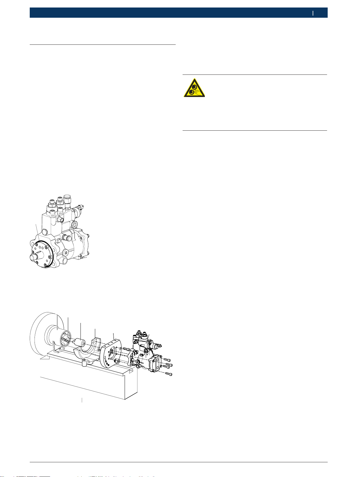
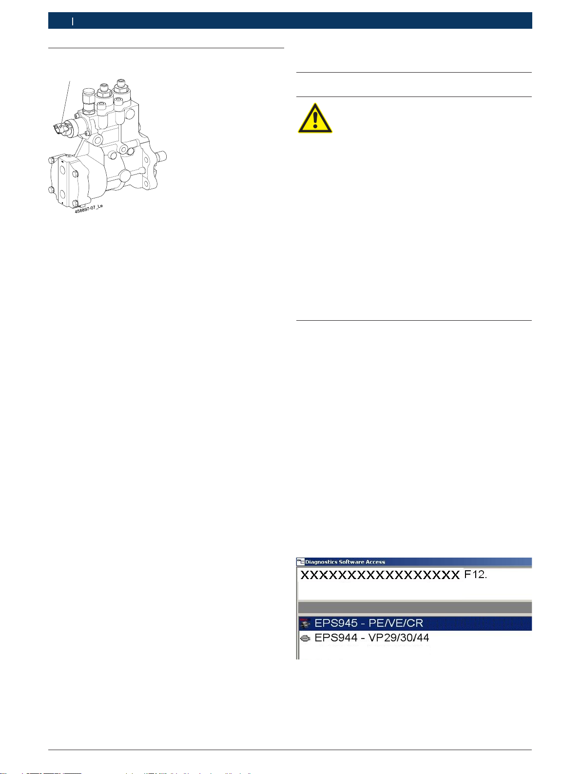
1
Abb. 1: CB28
1 CB28 Flansch O-Ring
Vorgehensweise:
458897-10_Le
1
23456
Abb. 2: Pumpenaufspannung
1 Schutzhaube
2 Antriebskupplung
3 Kupplungshälfte
4 Aufspannwinkel
5 Aufspannflansch mit 4 Sacklochbohrungen zur Aufbewahrung
der 4 Sechskantschrauben (4 x M10 x 30 ISO 4017-8.8)
6 CB28
iDie Antriebskupplung 1686401026 (Abb.2, Pos. 2)
und die Schutzhaube 1685510148 (Abb.2, Pos. 1)
sind Lieferumfang vom EPS815. Der Aufspannwinkel
1 688 010 129 (Abb.2, Pos.4) ist Sonderzubehör
bei EPS und muss für die Prüfung beschafft werden.
Warnung - Einzugsgefahr!
Durch drehende oder bewegte Teile bei
laufenden Antrieb können Körperteile oder
Kleidungsstücke erfasst und eingezogen
werden.
¶Schutzhaube mit einem Abstand < 5 cm
zur Schwungscheibe montieren.
iDie zulässigen Anziehdrehmomente für die Auf-
spannteile, Antriebskupplungen und Schläuche
erhalten Sie aus der entsprechenden Erzeugnisprüf-
anleitung in der Bosch ESI[tronic].
1. Antriebskupplung (Abb.2, Pos.2) am Schwungrad
des EPS befestigen.
2. Schutzhaube (Abb.2, Pos.1) über die Antriebskupp-
lung (Abb.2, Pos.2) bis zum Schwungrad schieben.
3. Scheibenfeder der CB28 in die Nut der Antriebswelle
stecken.
4. Die Kupplungshälfte (Abb.2, Pos.3) auf die An-
triebswelle der CB28 so montieren, dass die
Scheibenfeder überdeckt ist. Zum Gegenhalten den
Montierschlüssel 1687951030 verwenden. Anzieh-
drehmoment= 160Nm- 165Nm.
5. Montagehülse auf die Kupplungshälfte stecken.
6. Den Radialwellendichtring des Aufspannflansches
und die Montagehülse leicht einölen.
7. Den Aufspannflansch (Abb.2, Pos.5) an die CB28
mit den 4 Sechskantschrauben montieren.
8. Montagehülse entfernen.
9. CB28 mit Aufspannflansch in den Aufspannwinkel
(Abb.2, Pos.4) setzen und befestigen.
10. CB28 zur Antriebskupplung (Abb.2, Pos.2) schieben.
11.Die Kupplungshälfte (Abb.2, Pos.3) der CB28
zwischen den Klemmbacken der Antriebskupplung
(Abb.2, Pos. 2) einspannen.
12.Schutzhaube (Abb.2, Pos.1) über die Antriebskupp-
lung (Abb.2, Pos. 2) und Kupplungshälfte (Abb2,
Pos.3) schieben und befestigen.
13.Das Schwungrad des EPS von Hand drehen und
sicherstellen, dass keine Schleifgeräusche zwischen
Schutzhaube (Abb.2, Pos.1), Antriebskupplung
(Abb.2, Pos. 2) und Kupplungshälfte (Abb.2,
Pos.3) auftreten. Falls Schleifgeräusche auftreten,
den Sitz der Schutzhaube korrigieren.
14.Den Aufspannwinkel (Abb.2, Pos.4) über die bei-
den Befestigungsschrauben auf die Aufspannkonsole
befestigen.

1 689 989 212 2014-10-31| Robert Bosch GmbH
8 | 1 687 010 496 | Vorbereitung zur Prüfungde
4.2 CB 28 hydraulisch an anschließen
4.2.1 Ohne automatische Druckregelung
458897-11_Le
1
2
3
6
7
8
9
10
11
12
13
14
15
4
5
16
Abb. 3: Gesamtübersicht Hydraulikanschluss EPS815 ohne
automatischer Druckregelung
1 Schlauchleitung 1 680 712 367 mit Durchflussdrossel D2,4mm
für Prüfölzulauf, mit Überwurfmutter und Schneidring
2 Hochdruckausgänge mit Hochdruckschläuche 1 687 016 064
3 Schlauchleitung 1 680 712 373 für Prüfölrücklauf
4 Gewindestück M16 x 1,5 / m14 x 1,5, Anschluss OUT
5 Gewindestück M16 x 1,5 / m14 x 1,5, Anschluss IN
6 Manometer 0 986 613 103 (-1–5bar)
7 Teilesatz Ablassventil 0 986 615 075 für Manometer
0986613103
8 Absperrhahn Prüfölrücklauf
9 Hydraulikschlauch mit G 1/8 - Kupplung 1 680 712 327
10 Schlauchleitung 1 680 712 202 (Prüfölzulauf mit Überwurfmut-
tern, Schneidringen, Ringstutzen M14x1,5 und Prüfadapter
11 Schmierölzulauf EPS
12 Schmierölrücklauf EPS
13 Hydraulikschlauch mit G 1/8 - Kupplung 1 680 712 327
14 Teilesatz Ablassventil 0 986 615 075 für Manometer
0986613102
15 Manometer 0 986 613 102 (0–16bar)
16 Einschraubstutzen 1 683 356 133; Anziehdrehmoment M10x1 =
8,5Nm- 11,5 Nm

1 689 989 212 2014-10-31|Robert Bosch GmbH
Vorbereitung zur Prüfung | 1 687 010 496 | 9 de
4.2.2 Mit automatischer Druckregelung LPC800
458897-09_Le
1
2
3
4
5
6
7
8
9
10
11
12
13
15
17
14
16
18
Abb. 4: Gesamtübersicht Hydraulikanschluss EPS815 mit auto-
matischer Druckregelung LPC800
1 Schlauchleitung 1 680 712 367 mit Durchflussdrossel D2,4mm
für Prüfölzulauf, mit Überwurfmutter und Schneidring
2 Hochdruckausgänge mit Hochdruckschläuche 1 687 016 064
3 Schlauchleitung 1 680 712 373 für Prüfölrücklauf
4 Gewindestück M16 x 1,5 / m14 x 1,5, Anschluss OUT
5 Gewindestück M16 x 1,5 / m14 x 1,5, Anschluss IN
6 Manometer 0 986 613 103 (-1–5bar)
7 Teilesatz Ablassventil 0 986 615 075 für Manometer
0986613103
8 Hydraulikschlauch mit G 1/8 - Kupplung 1 680 712 327
9 Schlauchleitung zu Temperatursensor B47 (Prüfölrücklauf)
10 Schlauchleitung zu Drucksensor B49 (Zulaufdruck)
11 Drucksensor B49 (Prüfölzulauf)
12 Drucksensor B48 (Unterdruck), nicht belegt
13 Tempertatursensor B47 (Prüfölrücklauf)
14 Tempertatursensor B46 (Prüfölzulauf), nicht belegt
15 Schlauchleitung 1 680 712 202 (Prüfölzulauf) mit Überwurfmut-
tern, Schneidringen, Ringstutzen M14x1,5 und Prüfadapter
16 Schmierölrücklauf EPS 815
17 Schmierölzulauf EPS 815
18 Einschraubstutzen 1 683 356 133; Anziehdrehmoment M10x1 =
8,5Nm- 11,5 Nm

1 689 989 212 2014-10-31| Robert Bosch GmbH
10 | 1 687 010 496 | Vorbereitung zur Prüfungde
5. Prüfung
5.1 EPS einschalten
Warnung - Verletzungsgefahr durch aus-
tretendes Prüföl oder durch wegfliegende
Teile!
Bei nicht ordnungsgemäßem hydraulischen
Anschluss der Prüfausrüstung und der
Common Rail Pumpe, kann beim Starten der
Prüfung Prüföl unter hohem Druck austreten
oder Bauteile der Prüfausrüstung bersten.
Dadurch kann es zu Verletzungen oder zu
Sachschäden kommen.
¶Vor dem Einschalten prüfen, ob alle
Schlauchleitungen an der Prüfausrüstung
und an der Common Rail Pumpe ord-
nungsgemäß angeschlossen sind.
¶Spritzschutzgehäuse erst öffnen, wenn
der Antrieb des EPS stillsteht.
¶Undichte und defekte Schlauchleitungen
austauschen.
1. Am EPS 815 den Absperrhahn (Abb 3, Pos. 8) vom
Prüfölrücklauf schließen.
iNur bei bei Prüfaufbau ohne automatischer Druckre-
gelung erforderlich.
2. EPS am Hauptschalter einschalten.
3. Software EPS 945 - PE/VE/CR (Abb.6) für die
CB28- Prüfung auswählen und starten.
Software führt eine Initialisierung durch und die
Statusanzeigen leuchten grün auf.
4. Umrichter / Prüfölpumpe, Schmierölversorgung und
Prüfölheizung am EPS - Bedienteil einschalten.
5. Zulaufdruck auf 0,1 bar – 0,2 bar einstellen.
6. Reglerfreigabe für den Antriebsmotor am EPS - Be-
dienteil einschalten.
"EPS und Prüfsatz CRS 845H sind für die Pumpen-
Prüfung betriebsbereit.
Abb. 6: Software EPS 945 - PE/VE/CR
4.3 CB 28 elektrisch anschließen
1
Abb. 5: Elektrischer Anschluss
1 ZME
¶ZME-Anschlussleitung 1684 462511 oder
1684463706 des EPS mit Adapterleitung
1684460255 an die ZME (Abb.5, Pos.1) der
CB28 anschließen.

1 689 989 212 2014-10-31|Robert Bosch GmbH
Prüfung | 1 687 010 496 | 11 de
6. Instandhaltung
6.1 Wartungsintervalle
Wartungsarbeit
wöchentlich
2-jährlich*)
Schlauchleitungen prüfen (siehe Kap. 6.2) X X
*) Bei Hauptinspektion vom Prüfdienst/Kundendienst durchzuführen
6.2 Schlauchleitungen prüfen
Alle Schlauchleitungen (Hochdruckschlauchleitungen
und Niederdruckschlauchleitungen) immer sorgsam
behandeln und vor Gebrauch überprüfen. Schlauchlei-
tungen sind zu ersetzen, wenn bei der Überprüfung fol-
gende Beschädigungen festgestellt werden:
RRisse, Versprödungen, Scheuerstellen oder Blasen
am Schlauchmantel
RGeknickte Schlauchleitung
RSchwergängige Überwurfmuttern oder Schnellkupp-
lungen
RVerformte oder beschädigte Anschluss-Seite der
Schlauchleitung (Dichtkegel, Stecknippel, etc.)
RUndichte Stellen an der Armatur
RKorrosion an der Armatur wenn dadurch die Festig-
keit vermindert wird
RÜberschreitung der Verwendungsdauer
(siehe Kapitel 6.3)
!Beschädigte Schlauchleitungen dürfen nicht repa-
riert werden.
6.3 Hochdruckschlauchleitung tauschen
Hochdruckschlauchleitungen (Betriebsdruck größer
60bar) nach 3 Jahren ersetzen (siehe Fertigungsdatum
auf Hochdruckschlauchleitung), auch wenn keine si-
cherheitsrelevanten Mängel erkennbar sind.
5.2 Prüfablauf starten
1. In der System-Software im Dialogfenster "Komponen-
tenauswahl" den gewünschten Prüfablauf aufrufen.
2. Messbild aufrufen.
3. Prüfschritt "1" auswählen.
4. Im Auswahlmenü "Messfunktionen" Funktion Auto-
matik Ein/Aus aktivieren.
Das Automatiksymbol blinkt in der Betriebszu-
standsanzeige.
5. Prüfung starten mit <F8>.
6. Zulaufdruck für die Pumpe einstellen.
7. Im Auswahlmenü "Messfunktionen" Funktion Kana-
lerkennung aktivieren.
Die Software führt eine automatische Erkennung
der aktiven Messkanäle durch.
" Prüfsystem und CB28 sind für die Prüfung betriebs-
bereit.
5.3 Beschreibung der Pumpenprüfung
Nach Start der Prüfung und bei eingeschalteter Auto-
matik beginnt sofort nach Erreichen der vorgegebenen
Sollwerte die Warte- bzw. die Messzeit zu starten. Nach
Ablauf der Zeiten wechselt die Software automatisch in
den nächsten Prüfschritt und speichert dabei die Mess-
ergebnisse für das Messprotokoll ab.
Ist der letzte Prüfschritt erreicht und die Messzeiten
sind abgelaufen, regelt der Prüfstand ab und die Prü-
fung ist beendet.
Mit <F12> kann das Messprotokoll aufgerufen werden.

1 689 989 212 2014-10-31| Robert Bosch GmbH
12 | 1 687 010 496 | Außerbetriebnahmede
7. Außerbetriebnahme
7.1 Ortswechsel
¶Bei Weitergabe von 1 687 010 496 die im Lieferumfang
vorhandene Dokumentation vollständig mit übergeben.
¶1 687 010 496 nur in Originalverpackung oder
gleichwertiger Verpackung transportieren.
7.2 Entsorgung und Verschrottung
7.2.1 Wassergefährdende Stoffe
!Öle und Fette sowie ölhaltige und fetthaltige Abfälle
(z. B. Filter) sind wassergefährdende Stoffe.
1. Wassergefährdende Stoffe nicht in die Kanalisation
gelangen lassen.
2. Wassergefährdende Stoffe gemäß den geltenden
Vorschriften entsorgen.
7.2.2 1 687 010 496 und Zubehör
¶1 687 010 496 zerlegen, nach Material sortieren und
gemäß den geltenden Vorschriften entsorgen.
1 687 010 496, Zubehör und Verpackungen
sollen einer umweltgerechten Wiederverwer-
tung zugeführt werden.
¶1 687 010 496 nicht in den Hausmüll
werfen.
Nur für EU-Länder:
1 687 010 496 unterliegt der europäischen
Richtlinie 2012/19/EU (WEEE).
Elektro- und Elektronik-Altgeräte einschließ-
lich Leitungen und Zubehör sowie Akkus und
Batterien müssen getrennt vom Hausmüll
entsorgt werden.
¶Zur Entsorgung, die zur Verfügung stehen-
den Rückgabesysteme und Sammelsysteme
nutzen.
¶Umweltschäden und eine Gefährdung der
persönlichen Gesundheit durch die ord-
nungsgemäße Entsorgung vermeiden.
6.4 Radialwellendichtring tauschen
Den Radialwellendichtring vom Aufspannflansch
1685720356 tauschen, wenn Beschädigungen an der
Dichtlippe oder Undichtigkeiten bei der Pumpenprüfung
erkannt werden.
1
2
3
4
Abb. 7: Aufspannflansch mit Radialwellendichtring
1. Mit einem Durchschlag (D = 3 mm), durch die 3 Boh-
rungen des Aufpannflansches (Abb. 7, Pos. 1, 2, 3),
den Radialwellendichtring (Abb. 7, Pos. 4) aus dem
Sitz austreiben
2. Den neuen Radialwellendichtring außen leicht ein-
ölen und gerade auf den Sitz des Aufspannflansches
legen.
3. Mit einer Handpresse und einem Montagehilfsmittel
(z.B. Platte mit ebener Fläche, die den Radialwel-
lendichtring komplett überdeckt), den Radialwellen-
dichtring bündig einpressen.
4. Den Radialwellendichtring nach 2 Minuten Wartezeit
nachdrücken.
6.5 Ersatz- und Verschleißteile
Benennung Sachnummer
Aufspannflansch (für Flansch D = 85 mm)
RRadialwellendichtring (FKM - 60 x 80 x 7) <)
REinschraubverschraubung (G 1/2") <)
1 685 720 356
1 680 209 032
1 683 391 152
Kupplungshälfte (D=24,8, M18 x 1,5) <)
RSechskantbundmutter (M18 x 1,5) <)
RO-Ring (30 x 3 mm) <)
1 686 430 059
1 683 314 017
1 680 210 134
Montagehülse 1 680 506 040
Montierschlüssel 1 687 951 030
Schlauchleitung <)
RStecknippel (G 1/8") <)
1 680 712 367
1 684 484 012
Schlauchleitung <) 1 680 712 202
Ringstutzen (M14 x 1.5/ AD15/ 24°) <) 1 683 385 056
Schlauchleitung <) 1 680 712 373
Prüfadapter <)
RStecknippel (M8 x 1)<)
0 986 613 091
0 986 613 089
Einschraubstutzen (M10 x 1) <)l 1 683 356 133
Hohlschraube (2 x 10 (3-4) DIN 7643-9SM-
NPB2) <) 2 911 201 703
Gewindestück (M14 x 1,5 / M16 x 1,5) <) 2 413 359 003
<) Verschleißteile
!Prüföl nach ISO 4113 gehört zur Altölsammelkate-
gorie 1. In der Altölsammelkategorie 1 dürfen keine
Anteile artfremder Stoffe, z. B. Altöle einer anderen
Kategorie oder Benzin oder Diesel enthalten sein.
Die zugehörige Abfallschlüsselnummer entnehmen
Sie dem Sicherheitsdatenblatt des Prüföls.

1 689 989 212 2014-10-31|Robert Bosch GmbH
| 1 687 010 496 | 13 en
1. Symbols used 14
1.1 In the documentation 14
1.1.1 Warning notices -
Structure and meaning 14
1.1.2 Symbols in this documentation 14
1.2 On the product 14
2. User information 14
2.1 Important notes 14
2.2 Safety instructions 14
2.3 General Instructions 14
3. Product description 15
3.1 Intended use 15
3.2 Scope of delivery 15
3.3 Special accessories 15
3.4 Prerequisites 15
3.5 Installing the EPS 945 software 15
4. Preparation for testing 16
4.1 Clamping the CB 28 16
4.2 Hydraulic connection of CB28 17
4.2.1 Without automatic pressure control 17
4.2.2 With automatic pressure control
LPC800 18
4.3 Electrically connecting the CB 28 19
5. Testing 19
5.1 Switching on the EPS 19
5.2 Starting the test procedure 20
5.3 Description of the pump test 20
6. Maintenance 20
6.1 Maintenance intervals 20
6.2 Check exhaust gas sampling hoses 20
6.3 Replacing the high-pressure hose 20
6.4 Replacing radial shaft seal 21
6.5 Spare and wearing parts 21
7. Decommissioning 21
7.1 Change of location 21
7.2 Disposal and scrapping 21
7.2.1 Substances hazardous to water 21
7.2.2 1 687 010 496 and accessories 21
Contents English

1 689 989 212 2014-10-31| Robert Bosch GmbH
14 | 1 687 010 496 | Symbols useden
1. Symbols used
1.1 In the documentation
1.1.1 Warning notices -
Structure and meaning
Warning notices warn of dangers to the user or people
in the vicinity. Warning notices also indicate the con-
sequences of the hazard as well as preventive action.
Warning notices have the following structure:
Warning
symbol
KEY WORD – Nature and source of hazard!
Consequences of hazard in the event of fail-
ure to observe action and information given.
¶Hazard prevention action and information.
The key word indicates the likelihood of occurrence and
the severity of the hazard in the event of non-obser-
vance:
Key word Probability of
occurrence
Severity of danger if in-
structions not observed
DANGER Immediate impend-
ing danger
Death or severe injury
WARNING Possible impending
danger
Death or severe injury
CAUTION Possible dangerous
situation
Minor injury
1.1.2 Symbols in this documentation
Symbol Designation Explanation
!Attention Warns about possible property damage.
iInformation Practical hints and other
useful information.
1.
2.
Multi-step
operation
Instruction consisting of several steps.
eOne-step
operation
Instruction consisting of one step.
Intermediate
result
An instruction produces a visible inter-
mediate result.
"Final result There is a visible final result on com-
pletion of the instruction.
1.2 On the product
!Observe all warning notices on products and ensure
they remain legible.
2. User information
2.1 Important notes
Important information on copyright, liability and warran-
ty provisions, as well as on equipment users and com-
pany obligations, can be found in the separate manual
"Important notes on and safety instructions for Bosch
Diesel Test Equipment". These instructions must be care-
fully studied prior to start-up, connection and operation
of the 1 687 010 496 and must always be heeded.
2.2 Safety instructions
All the pertinent safety instructions can be found in
the separate manual "Important notes on and safety
instructions for Bosch Diesel Test Equipment". These
instructions must be carefully studied prior to start-up,
connection and operation of the 1 687 010 496 and
must always be heeded.
2.3 General Instructions
These instructions are only valid in conjunction with the
instructions supplied for the:
REPS 815 injection pump test bench (1689979672)
RContinuous flow-rate measurement system
KMA 802/822 (1 689 979 674)
RTester set for common rail pumps CRS 845H
(1 689 979 863)
These instructions must also be kept together with and
forwarded together with the instructions listed above.

1 689 989 212 2014-10-31|Robert Bosch GmbH
Product description | 1 687 010 496 | 15 en
3. Product description
3.1 Intended use
This accessory kit contains clamping accessory and
connection accessories for the testing of common rail
pumps CB 28 (hereinafter referred to as CB 28) in con-
junction with the EPS 815, with lubricating oil supply
and tester set CRS 845H.
3.2 Scope of delivery
Designation Part number
Fixing flange (for flange 85 mm) with
4 blind holes for hexagon bolt (4 x M10 x 30
ISO 4017-8.8)
1 685 720 356
Hexagon bolt (4 x M10 x 30 ISO 4017-8.8) 2 911 061 761
Washer (4 x DIN 125-A10.5-ST) 2 916 011 018
Coupling half (D=24.8, M18 x 1.5) 1 686 430 059
Mounting sleeve for coupling half 1 680 506 040
Mounting wrench for coupling half 1 687 951 030
Exhaust gas sampling hose (suction line
with flow restrictor D = 2.4 mm) 1 680 712 367
Exhaust gas sampling hose (supply) 1 680 712 202
Union nut (2 x A2L15 DIN 3870) 2 915 101 009
Cutting ring (2 x 15 DIN 3861) 2 916 673 008
Inlet union (2 x M14X1.5/ AD15/ 24°) 1 683 385 056
Test adapter (M14 x 1.5 / plug-in hose nip-
ple) 0 986 613 091
Inlet union screw (2 x 10(3-4) DIN
7643-9SMNPB2) 2 911 201 703
Flat sealing ring (8 x A14X18 DIN 7603-CU) 2 916 710 609
Threaded piece (M16x1.5 / M14x1.5) 2 413 359 003
Flat sealing ring (2 x A16X20 DIN 7603-CU 2 916 710 611
Threaded socket (M10x1, ISO 8434-1-L10) 1 683 356 133
Hose line (return) 1 680 712 373
Flat sealing ring (3 x DIN 7603 A 10 X 13.5
-Cu 2 916 710 605
Screw clamp (10 - 16 mm) 1 681 314 078
Hydraulic hose (2 x G 1/8 - coupling) 1 680 712 327
CD-Testdata Vers. 2014/C or higher 1 687 370 318
iThe order numbers in the 'Scope of delivery' chapter
are only for information.
3.3 Special accessories
Designation Part number
Pressure gauge 0–1600 kPa (0 – 16 bar) 0 986 613 102
Pressure gauge -100–500 kPa (-1 – 5 bar) 0 986 613 103
Parts set for drain valve (2 x) 0 986 615 075
3.4 Prerequisites
REPS 815
RTest set CRS 845H (1 687 002 845).
RSoftware EPS 945, Version 4.35 or higher
ROperating knowledge on the EPS 815 with lubricat-
ing-oil supply and on tester set CRS 845H.
RGood knowledge of the mode of operation of com-
mon rail pumps.
3.5 Installing the EPS 945 software
1. Insert the "EP software" CD in the DVD/CD drive.
Installation of the software then starts automat-
ically.
The dialog box, "Select Setup Language", is dis-
played.
2. Comply with the instructions and install the soft-
ware.

1 689 989 212 2014-10-31| Robert Bosch GmbH
16 | 1 687 010 496 | Preparation for testingen
4. Preparation for testing
4.1 Clamping the CB 28
iA general description is provided. You will obtain
further information about handling the clamping
components and multi-plate clutches required to
clamp pumps from the appropriate product instruc-
tions in the Bosch ESI[tronic].
!Before you clamp the CB28 (fig.2, item6) pump on
the EPS, check the ease of movement of the pump
drive shaft and check the pump housing for cracks.
Pumps on which the drive shaft does not move freely
or is blocked, or with the housing cracked may not
be clamped and tested.
!Ensure that the housing O-ring (fig.1, item1) is
mounted on the CB28 (also see ESI[tronic] spare
parts list).
1
Fig. 1: CB28
1 CB28 flange O-ring
Procedure:
458897-10_Le
1
23456
Fig. 2: Pump clamping
1 Protective hood
2 Drive coupling
3 Coupling half
4 Clamping bracket
5 Clamping flange with 4 blind holes for storing the 4 hexagon
bolts (4 x M10 x 30 ISO 4017-8.8)
6 CB28
iThe drive coupling 1686401026 (fig.2, item 2)
and the protective hood 1685510148 (fig.2, item
1) are included in the scope of delivery of EPS815.
The angle plate 1 688 010 129 (fig.2, item4) is a
special accessory for EPS and must be procured for
the test.
Warning - danger of entanglement!
Due to rotating or moving parts when the
drive motor is running, body parts or cloth-
ing could be caught and pulled in.
¶Mount the protective hood at a distance
of < 5 cm from the flywheel.
iThe permissible tightening torques for the clamping
components, multi-plate clutches, and hoses are
provided in the appropriate product test instructions
in the Bosch ESI[tronic].
1. Attach the drive coupling (fig.2, item2) to the EPS
flywheel.
2. Slide protective hood (fig.2, item1) over the drive
coupling (fig.2, item2) and up to the flywheel.
3. Insert disk spring of the CB28 in the groove of the
drive shaft.
4. Fit coupling half (fig.2, item3) onto the drive
shaft of the CB28 in such a manner that the disk
spring is covered. Brace using mounting wrench
1687951030. Tightening torque =
160Nm–165Nm.
5. Fit the mounting sleeve onto the coupling half.
6. Apply a light coating of oil to the radial shaft seal of
the fixing flange and mounting sleeve.
7. Mount the fixing flange (fig.2, item5) to the CB28
using the 4 hexagon bolts.
8. Remove mounting sleeve.
9. Place CB28 with fixing flange into the angle plate
(fig.2, item4) and fasten.
10. Slide CB28 onto drive coupling (fig.2, item2).
11.Clamp the coupling half (fig.2, item3) on the CB28
between the clamping jaws of the drive coupling
(fig.2, item 2).
12.Slide protective hood (fig.2, item1) over the drive
coupling (fig.2, item 2) and coupling half (fig.2,
item3) and fasten.
13.Turn flywheel of EPS by hand and ensure that grind-
ing noises do not occur between protective hood
(fig.2, item1), drive coupling (fig.2, item 2), and
coupling half (fig.2, item3). If grinding noises oc-
cur, correct the seat of the protective hood.
14.Attach the angle plate (fig.2, item4) to the clamp-
ing bracket using the two fastening screws.

1 689 989 212 2014-10-31|Robert Bosch GmbH
Preparation for testing | 1 687 010 496 | 17 en
4.2 Hydraulic connection of CB28
4.2.1 Without automatic pressure control
458897-11_Le
1
2
3
6
7
8
9
10
11
12
13
14
15
4
5
16
Fig. 3: General overview of hydraulic connection of EPS815
without automatic pressure control
10 Hose line 1 680 712 367 with flow restrictor D2.4mm for test
oil supply with union nut and cutting ring
2 High-pressure outlets with high pressure hoses 1 687 016 064
3 Hose line 1 680 712 373 for test oil return
4 Threaded piece M16 x 1.5 / m14 x 1.5, OUT port
5 Threaded piece M16 x 1.5 / m14 x 1.5, IN port
6 Pressure gauge 0 986 613 103 (-1–5bar)
7 Parts set - drain valve 0 986 615 075 for pressure gauge
0986613103
8 Shut-off valve - test oil return
9 Hydraulic hose with G 1/8 - coupling 1 680 712 327
10 Hose line 1 680 712 202 (test oil supply with union nuts, cutting
rings, inlet unions M14x1.5 and test adapter
11 Lubricating oil supply/// EPS
12 Lubricating oil return EPS
13 Hydraulic hose with G 1/8 - coupling 1 680 712 327
14 Parts set - drain valve 0 986 615 075 for pressure gauge
0986613102
15 Pressure gauge 0 986 613 102 (0–16bar)
16 Threaded socket 1 683 356 133; tightening torque M10x1 =
8,5Nm–11,5Nm.

1 689 989 212 2014-10-31| Robert Bosch GmbH
18 | 1 687 010 496 | Preparation for testingen
4.2.2 With automatic pressure control LPC800
458897-09_Le
1
2
3
4
5
6
7
8
9
10
11
12
13
15
17
14
16
18
Fig. 4: General overview of hydraulic connection of EPS815
with automatic pressure control LPC800
10 Hose line 1 680 712 367 with flow restrictor D2.4mm for test
oil supply with union nut and cutting ring
2 High-pressure outlets with high pressure hoses 1 687 016 064
3 Hose line 1 680 712 373 for test oil return
4 Threaded piece M16 x 1.5 / m14 x 1.5, OUT port
5 Threaded piece M16 x 1.5 / m14 x 1.5, IN port
6 Pressure gauge 0 986 613 103 (-1–5bar)
7 Parts set - drain valve 0 986 615 075 for pressure gauge
0986613103
8 Hydraulic hose with G 1/8 - coupling 1 680 712 327
9 Hose line to temperature sensor B47 (test oil return)
10 Hose line to pressure sensor B49 (supply pressure)
11 Pressure sensor B49 (test oil supply)
12 Pressure sensor B48 (vacuum), not used
13 Tempertatur sensor B47 (test oil return)
14 Tempertaturesensor B46 (test oil supply), not used
15 Hose line 1 680 712 202 (test oil supply) with union nuts, cut-
ting rings, inlet unions M14x1.5 and test adapter
16 Lubricating oil return EPS 815
17 Lubricating-oil supply EPS 815
18 Threaded socket 1 683 356 133; tightening torque M10x1 =
8,5Nm–11,5Nm

1 689 989 212 2014-10-31|Robert Bosch GmbH
Preparation for testing | 1 687 010 496 | 19 en
5. Testing
5.1 Switching on the EPS
Warning - danger of injury due to escaping
test oil or flying parts!
If the hydraulic connections for the test
equipment and common rail pump are set
up incorrectly, test oil can escape at high
pressure or components of the test equip-
ment can burst when the test is started. This
can cause injury or material damage.
¶Before switching on, check that all hoses
on the test equipment and the common
rail pump are properly connected.
¶Do not open the splash guard until the
EPS drive motor has stopped.
¶Replace any leaky or faulty hose lines.
1. On the EPS 815, close the shut-off valve (fig. 3 item
8) of the test oil return.
iRequired only on test setup without automatic pres-
sure control.
2. Switch on the EPS at the main switch.
3. Select and start the EPS 945 - PE/VE/CR software
(fig. 6) for the CB18test.
The software performs an initialization and the
status displays light up green.
4. Switch on the converter / test oil pump, the lubricat-
ing-oil supply unit, and the test oil heater at the EPS
control unit.
5. Set the inlet pressure to 0.1 bar – 0.2 bar.
6. Switch on controller release for the drive motor at
the EPS control unit.
"The EPS and CRS 845H test set are ready for the
pump test.
Fig. 6: Software EPS 945 - PE/VE/CR
4.3 Electrically connecting the CB 28
1
Fig. 5: Electrical connection
1 ZME
¶Connect ZME connecting line 1684462511 or
1684463706 of the EPS using adapter cable
1684460255 to the ZME (fig.5, item1) of the
CB28.

1 689 989 212 2014-10-31| Robert Bosch GmbH
20 | 1 687 010 496 | Testingen
6. Maintenance
6.1 Maintenance intervals
Maintenance task
Weekly
2 yearly*)
Check hose lines (see sec. 6.2) X X
*) To be performed during the main inspection by test service/cus-
tomer service
6.2 Check exhaust gas sampling hoses
Always handle exhaust gas sampling hoses (high-
pressure and low-pressure hoses) with care and check
before use. Hoses are to be replaced if checking reveals
the following damage:
RCracks, brittle areas, abrasion or blistering of the
hose jacket
RKinked exhaust gas sampling hose
RStiff union nuts or quick-release couplings
RDeformed or damaged connection end of exhaust
gas sampling hose (sealing cone, plug-in nipple,
etc.)
RLeakage at hose fitting
RCorrosion at hose fitting if strength is reduced as a
result
RService life exceeded
(see sec. 6.3)
!Damaged hose lines must not be repaired.
6.3 Replacing the high-pressure hose
Replace high-pressure hoses (operating pressure great-
er than 60bar) after 3 years (see date of manufacture
on high-pressure hose) even if there are no apparent
defects of relevance to safety.
5.2 Starting the test procedure
1. In the system software, call up the desired test se-
quence in the 'Component selection' dialog box.
2. Call up the measurement screen.
3. Select test step '1'.
4. In the 'Measuring functions' selection menu, acti-
vate the Automatic on/off function.
The automatic mode symbol flashes in the operat-
ing status display.
5. Press <F8> to start the test.
6. Set the feed pressure for the pump.
7. In the 'Measuring functions' selection menu, activate
the Channel detection function.
The software automatically detects the active
measuring channels.
" The testing system and CB28 are ready for the test.
5.3 Description of the pump test
Once the test has been started and automatic mode
has been activated, the waiting and measuring times
begin as soon as the specified setpoints are reached.
After the times have elapsed, the software automati-
cally switches to the next test step and saves the test
results in the test protocol.
When the last test step is reached and the measuring
times have elapsed, the test bench comes to a stop and
the test is complete.
Press <F12> to call up the test protocol.
Table of contents
Languages:
Other Bosch Boiler Supplies manuals
Popular Boiler Supplies manuals by other brands

Immergas
Immergas 3.031186 Instruction and warning book

Viessmann
Viessmann VITOTRONIC 100 Operating instructions and user's information manual

Kemper
Kemper 612 07 001 installation manual

oventrop
oventrop Multiblock T-RTL Installation and operating instructions

Galmet
Galmet SG Fusion 100 Installation and operating manual