Centrometal Cm Pelet-set 90 Owner's manual

CENTROMETAL d.o.o. –Glavna 12 –40306 Macinec –Croatia
tel: +385 40 372 600; fax : +385 40 372 611
TECHNICAL INSTRUCTIONS
FOR THE COMMISSIONING AND ADJUSTMENT
Cm Pelet-set
(60-90 kW)
For boilers:
EKO-CK P 70-110
TUPS-90-M-01-2017-E-N-eng

Technical instructions for the commissioning and adjustment
2
CONTENTS
1. Introduction ...……………………………………………………………………………………………..
2. Status at delivery …………………………………………………………………………………………
3. Technical data ……………………………………………………………………………………………
4. Installation of Cm Pelet-set 90.……………………………………………………………..…………..
4.1. Installation of pellet burner and pellet control unit on boiler ..……………..…………...
4.2. Installation of pellet tank CPSP-800 and pellet feeder CPPT-90…………………..…..
5. Draught of the chimney..…………………………………………………………………………………
6. Boiler control unit …………………………………………………………………………………………
6.1. Description of control buttons and marks .………………………………………………...
6.2. Symbol description …………………………………………………………………………...
6.3. Basic setting of burner operation …….……………………………………………………..
6.4. The basic software configuration ..................................................................................
6.5. Fine tuning of operating parameters of the burner ….………………………...………….
6.6. Burner operation modes ……………………………………………………………………..
7. Interruption of power supply.…………………………………………………………………………….
8. Electrical connection.…………………………………………………………………………………….
3
3
3
4
4
8
8
8
8
9
9
10
12
16
20
20

Technical instructions for the commissioning and adjustment
3
1. Introduction
Cm Pelet-set 90,pellet based heating system (nominal burner output 60 to 90 kW) designed for
installation in combined boilers or biomass firing boilers EKO-CK P, with thermal output from 70 to
110 kW. These technical instructions present commissioning, as well as fine tuning of the burner
operating parameters. Installation, commissioning and fine tuning of Cm Pelet-set 90 must be carried
out by the manufacturer authorized fitter/serviceman
Use and maintenance instructions for Cm Pelet-set 90 in daily work are also supplied with these
instructions.
2. Mode at delivery
1. pellet burner CPPL-90
2. lower boiler door CPDV 60/70 for burner CPPL-90 (for boiler EKO-CK P 70) and CPDV
90/110 (for boilers EKO-CK P 90 i 110 - factory mounted onto EKO-CK P boilers
3. boiler control unit CPREG
4. pellet feeder CPPT-90
5. pellet tank CPSP-800
3. Technical data
Description:
1. pellet burner CPPL-90
2. tube for connecting of pellet feeding flexible tube
3. connectors for connecting of burner with control unit
4. Backfilling sensor / temperature gauge on inlet tube that
is installed tube for connecting of pellet feeding flexible
tube (backfilling sensor is detailed in the
Technical instructions for use and maintenance)
5. burner cover
6. plastic and silicone pressure switch pipe
7. feeder with electric motor CPPT-90
8. pellet feeder flexible tube
9. pellet tank CPSP-800
10. cover of opening for filling the pellet tank
11. lower lid for tank cleaning
12. opening for pellet feeder
13. openings for tank cleaning
14. lower boiler door adapted for pellet burner CPDV 60/70 for burner CPPL-90 (for boiler EKO-CK P
70) and CPDV 90/110 (for boilers EKO-CK P 90 i 110
15. connector for pressure switch silicone pipe
on the lower boiler door CPDV
16. boiler control unit CPREG
17. micro switch for lower boiler door

Technical instructions for the commissioning and adjustment
4
Cm Pelet-set 90 on boilers EKO-CK P
Cm Pelet-set type
90
90
90
Burner CPPL type
CPPL-90
CPPL-90
CPPL-90
Set thermal output
(kW)
60
70
90
Boiler type
EKO-CK P 70
EKO-CK P 90
EKO-CK P 110
Pellet tank volume
(l)
800
Pellet tank height
(mm)
1420
Pellet tank depth
(mm)
980
Pellet tank width
(mm)
1010
Supply voltage
V/Hz
230/50
Boiler width
(mm)
640
690
690
Lower boiler door CPDV
(mm)
CPDV 60/70 for burner CPPL-90 (for boiler EKO-CK P
70) and CPDV 90/110 (for boilers EKO-CK P 90 i 110)
4. Installation of Cm Pelet-set 90
Commissioning and fine adjustment of Cm Pelet-set 90 should be carried out by a professional or the
manufacturer’s authorized fitter.
4.1. Installation of pellet burner and pellet control unit on the boiler
a) Remove lower boiler door and install lower boiler door CPDV 60/70 for burner CPPL-90 (for
boiler EKO-CK P 70) and CPDV 90/110 (for boilers EKO-CK P 90 i 110) supplied with Cm
Pelet-set 90 (if lower boiler door CPDV is not already installed on the boiler).
b) Disassemble the burner into 4 parts as shown figure below. Place burner head (with fixed
thicker gasket toward door and thinner gasket on the side away from door) onto prepared
screws on the door, then place a feeding box and tighten the screws with enclosed nuts M8.
Put a gasket onto the feeding box and put a feeding tube onto it (faced toward the pellet tank,
either on the left or on the right side and tighten it firmly using enclosed screws M4 x 30.
Connect 3-pin plug of the backfilling sensor / temperature sensor'' the supply pipe in 3-pin
connector which is attached to the feeding box. PVC and silicone pipe, which is at its one end
fixed to the pressure switch at the burner, should be placed (and shorten if necessary) onto
appropriate connector on the boiler door. Place cover onto preinstalled screws and tighten
them firmly. In the end it is necessary to put the nozzle of the burner which is attaches to the
prepared screw on the burner head.

Technical instructions for the commissioning and adjustment
5

Technical instructions for the commissioning and adjustment
6
c) Drill 2 holes at the distance of 358 mm on the top side of boiler plating, and using enclosed
screws 3.9 x 9.5 mm fix boiler control unit CPREG, insert the safety thermostat sensor and
control unit sensor into the sleeve on the boiler (on the top side on EKO-CK P boiler) and
connect wires by 4-poles and 6-poles connectors onto the burner and then fix the connectors
to the burner body. Fix wire cable between the control unit and burner to the boiler casing by
supplied plastic cable holder (fix cable holder onto boiler casing with tapping screws 3.9 x 16
mm).
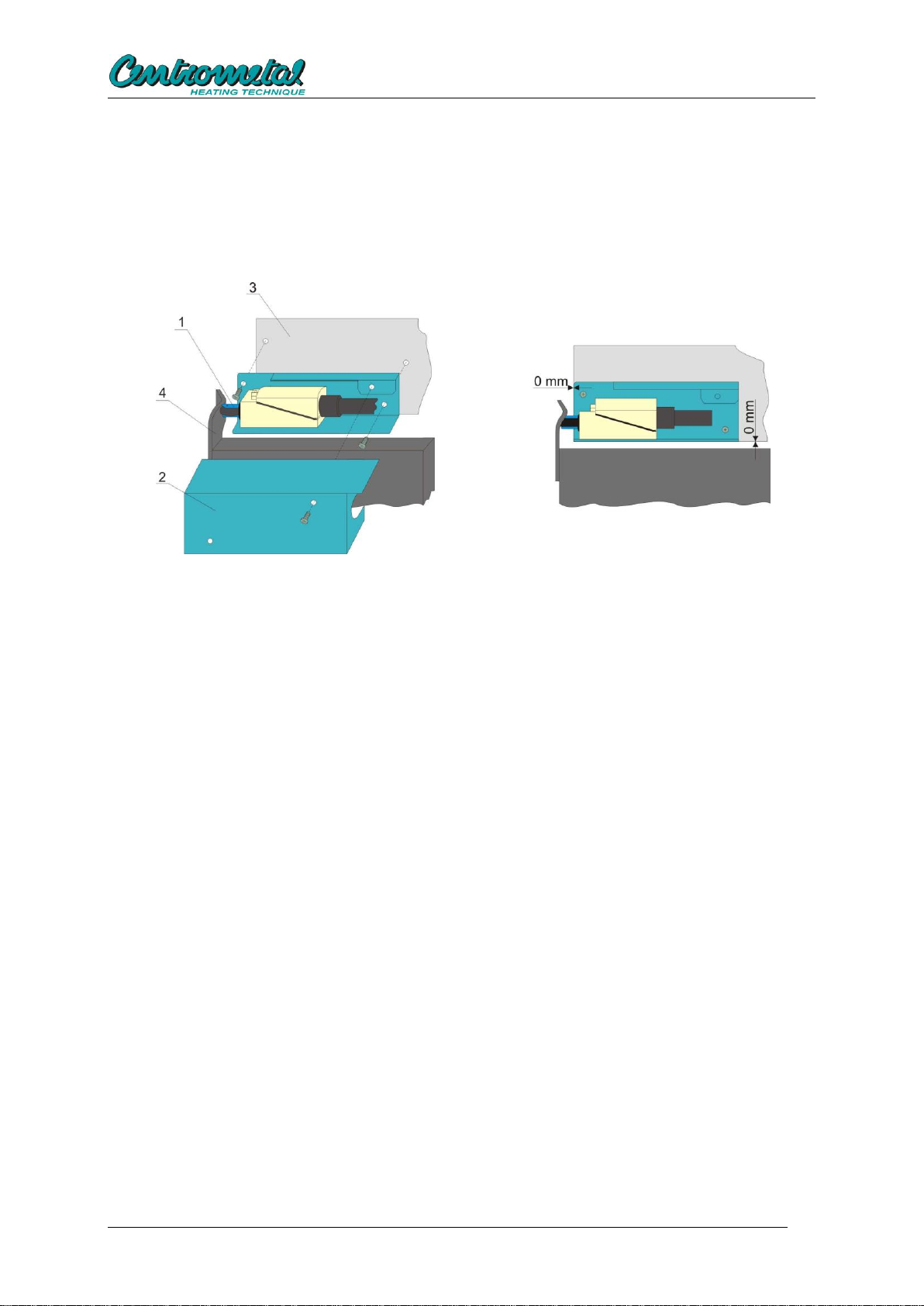
Mounting of the micro switch for lower boiler door
d) Set the micro switch (1) in lower left corner of the lower front casing of the boiler (3) using 2
screws, put the cover (2) according to the picture on micro switch and fasten it with the screw.
Check if lower boiler door, when they are closed, push the micro switch.
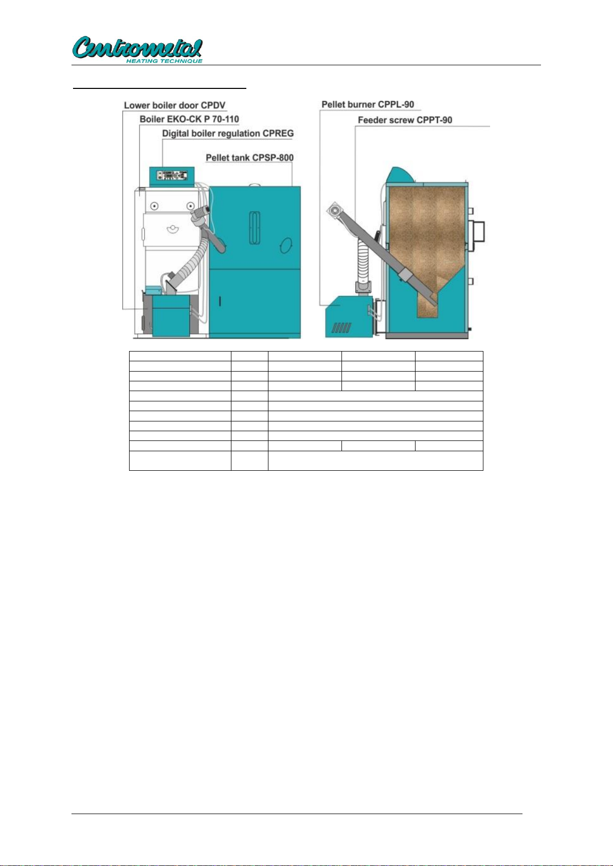
e) Assembly the pellet tank CPSP-800 according to technical instructions and position it next to
the right or left boiler side onto horizontal surface. Align tank bottom with the boiler bottom and
align the front tank side with the front side of boiler plating.
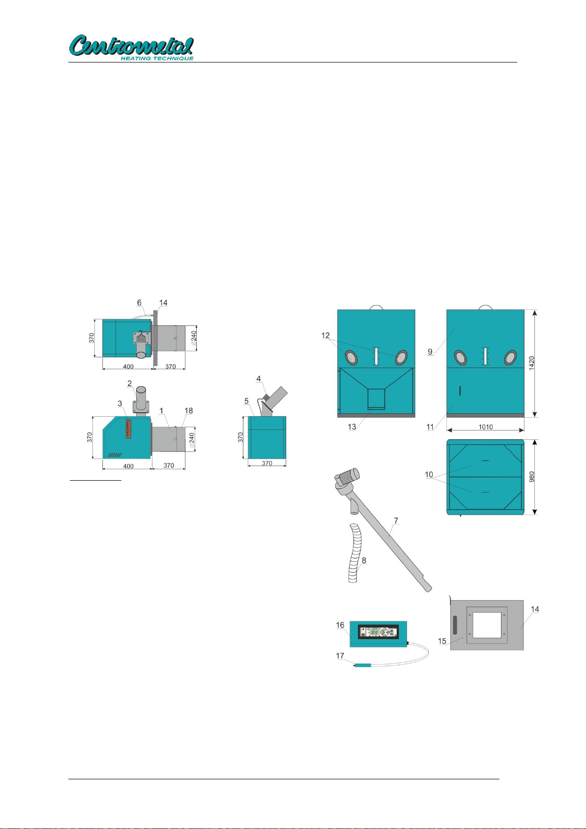
f) Place the feeder CPPT-90 into tank and connect it by a transparent flexible tube with a pellet
burner CPPL-90. Fix one end of transparent flexible tube to the burner (onto the feeding tube)
to backfilling sensor / temperature gauge on inlet tube, and other end should be fixed to the
feeder so that the tube will not become loosen. Transparent tube between the feeder and
burner must be as straight as possible so that pellets can fall smoothly from the feeder into the
burner (if pellets remain in the tube, it should be straighten and shorten, if necessary).
g) Connect a wire for power supply to the screw feeder CPPT-90 to the connector (2) on the
back side of the control unit CPREG.
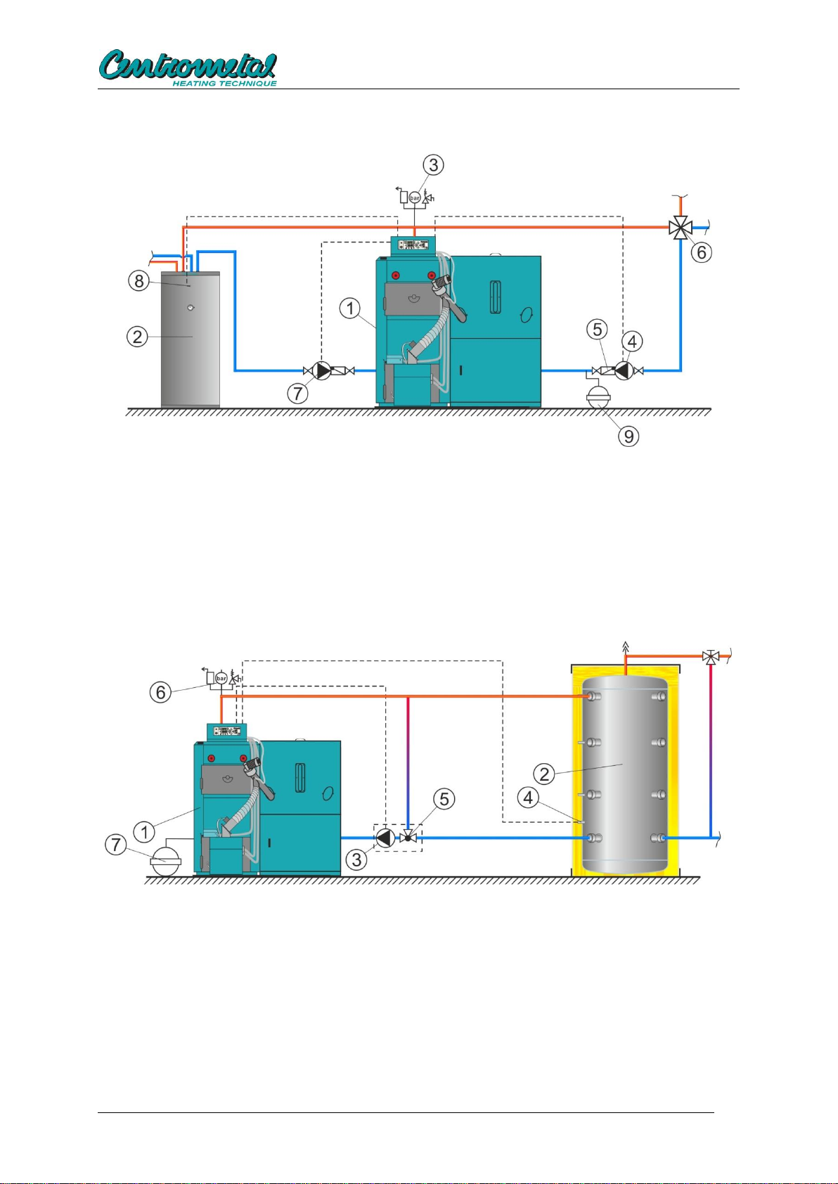
h) If sanitary water is prepared by using the boiler control unit, or the system installed one or
more accumulation tank (CAS) a sanitary water sensor should be fixed to connector 4 instead
of a jumper wire.
h1) If the sanitary water is prepared with the help of boiler control unit, sensor should
be placed in domestic hot water tank (Figure 1a).
h2) if it is installed one or more accumulation tanks (CAS) it is necessary to set the
domestic hot water sensor at the lowest sensor sleeve on the last accumulation
tank (CAS) or in a sensor tube below the water level we want to warm up (see
Figure 1b). In this case the hot water sensor has no direct connection with the
preparation of hot water (Figure 1b).
i) If used Telecontrol or cascade manager they is connected in place of a room thermostat
(Connector 3).
j) A jumper wire is factory installed in the place of room thermostat (connector (3). If an adapter
is used for ‘’more zones’’ control (optional equipment), a jumper wire in the connector (3) must
be put.
k) Do not connect boiler control unit to power supply via a built in thermostat on the boiler (if
there is a thermostat on the upper side of EKO-CK P boiler).

Technical instructions for the commissioning and adjustment
7
Figure 1a. Connection scheme of the boiler EKO-CK P 70,90 and 110 with in-built Cm Pelet-set
90 on heating installation with stainless steel hot water boiler:
1. Boiler EKO-CK P 70,90,110 with in-built Cm Pelet-set 90
2. Stainless steel hot water boiler TB
3. Air selfventing group
4. Heating system pump
5. Non-return valve
6. Manual 4-way mixing valve
7. Sanitary water pump
8. Sanitary water sensor
9. Expansion vassel (10% volume of water in the installation)
Figure 1b. Connection scheme of the boiler EKO-CK P 70,90 and 110 with in-built Cm Pelet-set
90 on heating installation with accumulation tank:
1. Boiler EKO-CK P 70,90,110 with in-built Cm Pelet-set 90
2. Accumulation tank (CAS)
3. Heating pump between boiler and accumulation tank (CAS)
4. Sanitary water sensor (at the lowest sensor sleeve on the accumulation tank (slučaj h2))
5. 3 - way thermostat valve for outlet protection (as ESBE VTC 512, VTC 531, LTC 141
or Laddomat 21)
6. Air selfventing group
7. Expansion vassel (10% volume of water in the installation)
4.2. Installation of CPSP-800 pellet tank and CPPT-90 pellet feeder
See Technical instructions for installation, use and maintenance of pellet tank and feeder supplied with
CPSP-800 pellet tank and CPPT-90 screw feeder.

Technical instructions for the commissioning and adjustment
8
5. Draught of the chimney
Chimney of appropriate size is one of conditions for proper operation of the boiler. Chimney has to be
select according to diagram for solid fuel firing (see Technical instructions EKO-CK P or EKO-CKB P)
or a chimney with the following minimum draughts has to be select for certain powers:
-Cm Pelet-set 60 = 24 Pa
-Cm Pelet-set 70 = 25 Pa
-Cm Pelet-set 90 = 28 Pa
6. Boiler control unit
Boiler control unit is supplied in a plasticized metal box prepared for installation on boilers EKO-CK P
70, 90 and 110.
6.1. Description of buttons and symbols on the control unit
Button
Function
Safety thermostat button.
0
1
Main switch to turn on/turn off power supply to the control unit
Start/stop button (on/off)
- By pressing the button for 3 sec. the burner turns on.
- While the burner operates, by pressing the button for 3 sec. the burner goes to
extinction phase.
- Short pressing of the button: Exit from parameter setting and their saving.
Entry button to the parameter setting menu and going to the next parameter
Setting of the selected parameter to higher value.
Setting of the selected parameter to lower value
Selection of the WINTER firing regime. In this regime the heating pump turns on and a
sanitary water pump also turns on if a sanitary water sensor and tank is built in.
Selection of the SUMMER firing regime. In this regime only the sanitary water pump
turns on if a sanitary water sensor is built in. If it is a boiler with sanitary hot water
heater inside the boiler water and if no sanitary water sensor and tank is built in,
neither the heating pump nor the sanitary water pump will turn on in the summer
regime.
Manual switch on of the pellet feeder. It is used to supply the feeder with pellets (after
tank cleaning, tank discharge…).

Technical instructions for the commissioning and adjustment
9
6.2. Symbol description
Indication of operation of the sanitary water heating pump
Indication of operation of the heating pump circuit.
Indication of turn on status of timer (time programmes)..
Indication of operation of pellet feeding screw feeder
Indication of flame presence in the burner
Indication of operation of the burner fan.
Indication of operation of electric heater (for firing of pellets).
An indication of activation errors except errors of safety pressure switch.
Indication of the safety pressure switch due to too high pressure in the boiler
combustion chamber
6.3. Basic setting of burner operation
Basic setting of burner operation is described in details in ''Technical instructions for use and
maintenance of Cm Pelet-set''.
Turning on of control unit
If control unit is turned on by a main
switch, it will be in OFF mode, i.e. the
burner does not work.
''OFF'' appears on the upper display,
and current time and current
temperature in boiler are alternately
displayed on the lower display.
Burner operating parameters can be set in
any operation mode (‘’ON’’ mode) or standby
mode (‘’OFF’’ mode) of the burner.
By longer pressing of ‘’SET’’ button the
parameter setting menu is entered, and by short
pressing of ‘’SET’’ button you can switch from
menu to menu.
Exit from a menu to home display and saving of
modified values is made by short pressing of
‘’On/Off’’ button or by passing through all 9
parameters and returning to the home display
In service menu you can move to next
parameter by short pressing of ‘’SET’’ button.
Exit from service menu, saving and return to
home display is done by short pressing of
‘’ON/OFF’’ button.
If no button is pressed within 90 seconds, the
control unit automatically exits the service menu
to home display without saving of modified
parameters..

Technical instructions for the commissioning and adjustment
10
6.4. The basic software configuration (by authorized service)
It is used for the case:
- on CentroPlus/-B boiler firing with solid fuel / pelets: adjusting the temperature of the boiler
for the first firing a pellet burner (for CentroPlus /-B boilers fired with solid fuel / wood pellets)
when working on wood without accumulation tank (CAS)
- adjust the maximum temperature in the accumulation tank (CAS) for the first firing a pellet
burner (if accumulation tank (CAS) is installed).
- Adjust the switch off of pump heating to accumulation tank (CAS)
- adjust the desired temperature in the accumulation tank (CAS) for the first firing a pellet
burner (if accumulation tank (CAS) is installed)
- Adjust the diference "D" of burner work
- Adjust the domestic hot water priority (must remain at the factory settings if the accumulation
tank (CAS) is built-in).
- adjustment work with external controller or remote control "telecontrol"
Service menu Pr09 for a basic software configuration
After entering the setting menu move to Pr09 programme by multiple short pressure on ‘’SET’’ button
and entering the correct ‘’PIN’’ for entering the service menu.
Pr09: PIN entry
Factory setting: OFF (turned off)
Available setting: Pin (turned on)
When ''+'' button is pressed, ‘’PIN’’ is displayed in the
lower display, and after that PIN can be entered; PIN
enables to enter the burner setting menu. PIN is the
following series of 5 buttons:
PIN is the following series of 5 buttons:
(-), (winter), (screw), (+),
(summer).
If a wrong PIN is entered, you may start the series
from the beginning at any time.
Exit from Pr09 is done by pressing SET button.
OP01 - The temperature of the boiler
for the first firing a pellet burner
(for CentroPlus /-B boilers fired with
solid fuel / wood pellets) when working
on wood without accumulation tank (CAS)
Factory setting: "0" (turned off)
Available setting: "0" ili "50...80 °C".
OP02 - maximum temperature in the accumulation
tank (CAS) for the first firing a pellet
burner (if accumulation tank (CAS) is
installed).
Factory setting: "0" (turned off)
Available setting: "0" ili 40...85 °C".
When ''+'' button is pressed ‘’ 40...85°C’’ is displayed
in the display (turned on - the first start of the burner
at a temperature below the accumulation tank
temperature setting). If "OP02" is turned on then
domestic hot water sensor is defined as a

Technical instructions for the commissioning and adjustment
11
accumulation tank sensor it is necessary to set at the
lowest sensor sleeve on the last accumulation tank
(CAS) or in sensor sleeve below the level that we
want to heat up in accumulation tank (CAS).
OP03 - Switch off of pump to accumulation tank
(CAS)
Factory setting: "0" (turned off)
Available setting: "0" ili 60°C...(90-(D+1).
When ''+'' button is pressed ‘’60°C...(90-(D+1)’’ is
displayed in the display.
if the "OP03" is "ON", Tboiler set ("Pr01") min.=
("OP03 set) + (D+1)°C).
D = diference of burner work
In case the built-in protection element return line
"OP03" should be set at a minimum temperature of
the opening of the protective elements +1.
OP04 - Desired temperature in the accumulation
tank (CAS) for the first firing a pellet
burner (if accumulation tank (CAS) is
installed).
Factory setting: "0" (turned off)
Available setting: "0" ili "20...90°C".
Not valid for the first start if active "OP02".
When ''+'' button is pressed "20...90°C" is displayed in
the display, diference applies the same as in the
boiler.
OP05 - Diference "D" of burner work
Factory setting: "0" (turned off), boiler diference
(and accumulation tank diference if "OP03" and
"OP04" is turned on) = 5°C.
Available setting: "0" ili "6...15°C".
When ''+'' button is pressed "6..15°C" is displayed in
the display - diference of the boiler (and accumulation
tank if "OP04" is turned on).
OP06 - Domestic hot water priority (must remain
at the factory settings if the accumulation tank
(CAS) is built-in).
Factory setting: "0" (turned off)
Available setting: "0" (turned off), "1" (turned on), "2"
(turned on).
"1" - a priority hot water (heat pump shuts down when
there is a requirement for a sanitary water)
"2" - when there is a need for sanitary water pump
heat for 5 minutes (if request) / stand 5 minutes
When is "OP02" and/or "OP04" is turned on, "OP06"
is doesn't have function.
If the accumulation tank is installed, the option must
be disabled ("0").

Technical instructions for the commissioning and adjustment
12
OP07 - Work with external controller or remote
control "telecontrol"
Factory setting: "0" (turned off)
Available setting: "0" (turned off), "1" (turned on).
"OP07" can be turned on ("1") if "OP01" and "OP02" is
turned off.
Turning off with "ON/OFF" button have a priority and
throughout the closing phase + 5 minute except hand
hitting the button "ON/OFF" can't start a burner (or
integrating the time will blend with the wait until after
the closing phases +5 minutes). The procedure to
cancel the action (simultaneous ignition "0 / 1" and
hold "ON / OFF") here goes.
OP08 - Setting functions for REL1- voltage
output 230V (OPTIONAL)
Factory setting "1" (Flap - not used).
Available setting:
0 - (off),
1 - (flap - not used)
2 - (air cleaning)
It cannot be selected the same setting Pr9_OP8 and
Pr9_OP9 except 0 - Off, or in default, / after resetting
to factory settings both values are factory setted to 1 -
flap. Any change to one-flap on something else is not
possible during work
OP09 –Setting functions for REL2- voltage free
contact NO/NC/COM (on optional board)
Factory setting "1" (Flap -not used).
Available setting:
0 - off
1 - flap (not used)
2 - air cleaning
3 - alarm (relay is switched on when there is no alarm,
selecting the appropriate connector on the PCB can
be obtained by peaceful or make contact).
It can not be selected the same setting Pr9_OP8 and
Pr9_OP9 except 0 - (off) or in default, / after resetting
to factory settings both values are the factory at 1-flap.
Any change to one-flap on something else is not
possible during work.
6.5. Fine tuning of burner operating parameters
If fine tuning of burner operating parameters (different quality of pellets, different chimney draught,…)
is required, pellet falling time and fan speed can be changed by entering the service menu.
Pr08 to fine tune the parameters of the burner
After entering the setting menu move to Pr08 programme by multiple short pressure on ‘’SET’’ button
and entering the correct ‘’PIN’’ for entering the service menu.

Technical instructions for the commissioning and adjustment
13
Pr08: PIN entry
Factory setting: OFF (turned off)
Available setting: Pin (turned on)
When ''+'' button is pressed, ‘’PIN’’ is displayed in the
lower display, and after that PIN can be entered; PIN
enables to enter the burner setting menu. PIN is the
following series of 5 buttons:
PIN is the following series of 5 buttons:
(-), (winter), (screw), (+),
(summer).
If a wrong PIN is entered, you may start the series
from the beginning at any time.
Exit from Pr08 is done by pressing SET button.
Service menu Pr08
Depending on the burner operation phase or stand-
by phase (OFF mode), the following is displayed in
displays after PIN is entered:
Burner is not operating (''OFF'' mode): Parameter
FP01 is displayed in the upper display, and set value
of the parameter is displayed in the lower display
Burner is operation (''ON'' mode): Current burner
parameter is displayed and set value of the
parameter is displayed in the lower display.
Symbols and values of a parameter are shown in a
table of fine tuning parameters.
Data saving and exit from service menu is done by
short pressing of ‘’ON/OFF’’ button.
After exit the service menu, it is possible, within 60 minutes, to follow current burner operating
parameters in the upper and lower display of the control unit. After 60 minute the overview function of
current parameters is cancelled and, in order to resume it, you have to enter PIN again and leave the
service menu (short push of ‘’ON/OFF’’ button).
Overview of the burner current mode
While the burner is operating, when ''-'' button is
pressed, the burner current mode is displayed in the
lower display, and time to go to new mode is
displayed in the upper display. Mode symbols are
described in section ‘’Burner modes’’.
Overview of the burner current mode
While the burner is operating, when ''-'' and ''SET''
buttons are pressed together, the burner current
parameter (FPXX) is displayed in the lower display,
and set value of the parameter is displayed in the
upper display.

Technical instructions for the commissioning and adjustment
14
Overview of the burner current mode
When the burner reached the set programme, when
''-'' button is pressed, the current burner output and
current burner sub-mode (for example, P6 1, P4 2,
P2 3…) are displayed in the lower display and 0000
is displayed in the upper display. Symbols of modes
and submodes are described in ‘’Burner modes’’.
When several times are overlapped in the transition burner operating mode, total times can be
accessed additionally by the following combination of buttons. These combinations are available only
in transition phase and only in case of simultaneous counting of 2 times.
Overview of the burner current mode
(only in transition phase)
While the burner is operating, if ''-'' and ''+'' buttons
are pressed simultaneously, transition phase (PPX)
is displayed in the lower display and total time of the
transition phase remaining to transition to the next
phase is counted down in the upper display. Mode
description can be found in ‘’Burner mode’’.
Overview of the burner current mode
(only in transition phase)
While the burner is operating, if ''-'', ''+'' and ''SET''
buttons are pressed simultaneously, the current
burner parameter (FPXX) is displayed in the lower
display, while the set parameter value is displayed in
the upper display.
Within 60 minutes after exit the service menu, fan revolution number can be seen on the control unit,
in any phase of the burner operation.
Overview of the current fan revolution number
While the burner is operating, if ''-'' and ''WINTER''
buttons are pressed simultaneously, current fan
revolution number (rpm), is displayed in the lower
display, while the set revolution number in that
phase is displayed in the upper display.
Overview of the current fan revolution number
While the burner is operating, if ''-'', ''SET'' and
''WINTER'' buttons are pressed simultaneously, the
current burner parameter (FPXX) (according to rpm)
is displayed in the lower display, while the set
parameter value is displayed in the upper display.

Technical instructions for the commissioning and adjustment
15
The table below shows times in seconds (sec.) and revolution number per minute (rpm) of individual
parameters with factory settings and available setting range
TABLE WITH FINE TUNING OF BURNER OPERATING PARAMETERS CPPL-90
Param.
Description
Factory
settings
Setting range
FP01
Time of initial pellet feeding
75 sec.
0 - 200 sec.
FP02
Time after which the burner, if in a continuous
phase of work, goes into automatic shutdown
phase and re-ignition
180 min.
0 or 60 - 360 min.
FP03
Time of fan operation at maximum voltage at
the beginning of the burner operation
10 sec.
0 - 999 sec.
FP04
Time for flame development, safety time
900 sec.
0 - 999 sec.
FP05
Working time of electric heater without fan
1 sec.
0 - 99 sec.
FP06
Working time of electric heater after photocell
has detected flame
100 sec.
0 - 300 sec.
FP07
Initial fire developing time from flame
occurrence to transition to P1
160 sec
0 - 999sec.
FP08
Not used
0
FP09
Fan working time in extinction phase at the
voltage of set programme
130 sec.
0 - 999 sec.
FP10
Fan working time at max. revolution number at
the end of burner operation
200 sec.
0 - 999 sec.
FP11
Fan revolution number during fire developing
from the beginning of initial pellet feeding to
transition to programme P1
1560 rpm
500 - 2600 rpm
FP12
Revolution number for programme P1
2200 rpm
500 - 2600 rpm
FP13
Screw working time in programme P1
4 sec.
0 –99 sec.
FP14
Screw stand by time in programme P1
11 sec.
0 –99 sec.
FP15
Screw working time in programme P2
4 sec.
0 –99 sec.
FP16
Screw stand by time in programme P2
10 sec.
0 –99 sec.
FP17
Screw working time in programme P3
4 sec.
0 –99 sec.
FP18
Screw stand by time in programme P3
8 sec.
0 –99 sec.
FP19
Screw working time in programme P4
5 sec.
0 –99 sec.
FP20
Screw stand by time in programme P4
6 sec.
0 –99 sec.
FP21
Screw working time in programme P5
6 sec.
0 –99 sec.
FP22
Screw stand by time in programme P5
5 sec.
0 –99 sec.
FP23
Screw working time in programme P6
8 sec.
0 –99 sec.
FP24
Screw stand by time in programme P6
5 sec.
0 –99 sec.
FP25
Revolution number for programme P2
2200 rpm
500 - 2600 rpm
FP26
Revolution number for programme P3
2200 rpm
500 - 2600 rpm
FP27
Revolution number for programme P4
2300 rpm
500 - 2600 rpm
FP28
Revolution number for programme P5
2330 rpm
500 - 2600 rpm
FP29
Revolution number for programme P6
2450 rpm
500 - 2600 rpm
FP30
Revolution number for additional fire
developing in set programme
180 rpm
0 - 500 rpm
FP31
Working time of additional fire developing in
set programme
300 sec.
0 –999 sec.
FP32
Burner work time in transition phase in
programme P1
200 sec.
0 –999 sec.
FP33
Burner work time in transition phase in
programme P2
60 sec.
0 –999 sec.
FP34
Burner work time in transition phase in
programme P3
60 sec.
0 –999 sec.
FP35
Burner work time in transition phase in
programme P4
48 sec.
0 –999 sec.
FP36
Burner work time in transition phase in
programme P5
30 sec.
0 –999 sec.

Technical instructions for the commissioning and adjustment
16
FP37*
Suction system configuration
0
0- suction
system is not
installed
1- suction
system is
installed
FP38*
START time
5 sec
1 –20 sec
FP39*
RUNNING time
45 sec
1 –360 sec
FP40*
END time
10 sec
1 –60 sec
FP41*
CYCLE PAUSE time
15 sec
1 –60 sec
FP42*
Maximum RUNNING TIME
30 min
30 –60 min
FP43*
NUMBER OF CYCLES until the sensor is covered
3
1 –20
FP44*
TYPE OF SENSOR
0
This parameter must
be always set on 0.
*parameters for additional equipment (pellet suction system, for detailed description see
technical instructions for installation and use of pellet suction system)
If value of any parameter is changed from its factory setting, the modified parameter is blinking to
enable the fitter/serviceman to notice such change.
Resetting to factory setting
To reset to factory setting, the control unit has to be
switched off on the main switch, then press
simultaneously „WINTER“ and „SUMMER“ buttons
and keep them pressed until main switch turns on.
Four 8 digits are displayed in the upper display, and
FAC X (X shows current set programme) is displayed
in the lower display.
FAC 3-Cm Pelet-set 50 kW
After that, both display return to initial settings: OFF is
displayed in the upper display and current time/current
boiler temperature are displayed in the lower display.
Overview of software version
Software version can be displayed by keeping ''-''
button pressed with simultaneous turning on of control
unit on the main switch. Software version is displayed
in the upper display, and four ''-'' signs are displayed in
the lower display.
6.5. Burner operating mode
The burner operation in each mode (current mode can be seen on displays of the control unit) is
described below:
Mode A0:
Fan is operating at max. speed and after expiry time FP3 it goes to Mode A1.
If '-' is pressed, A0 Mode is displayed in the lower display and time to FP3 is counted down in the
upper display.
If '-' and 'SET' are pressed, „FP:03“ Mode is displayed in the lower display and FP3 parameter value is
displayed in the upper display
Mode A1:
Counting down of FP4 safety time starts (flame should appear in this time).

Technical instructions for the commissioning and adjustment
17
Fan turns off and heater turns on. After expiry of FP5 time, it goes to Mode A2.
If '-' is pressed, A1 Mode is displayed in the lower display and time to FP5 is counted down in the
upper display.
If '-' and 'SET' are pressed, „FP:05“ is displayed in the lower display, and FP5 parameter value is
displayed in the upper display.
Mode A2:
Screw turns on, fan turns on to FP11 speed, and heater still works.
Upon expiry of FP1, it goes to Mode A3.
If '-' is pressed, A2 Mode is displayed in the lower display and time to FP1 is counted down in the
upper display.
If '-' and 'SET' are pressed, „FP:01“ is displayed in the lower display, and FP1 parameter value is
displayed in the upper display.
Mode A3:
If FP4 expires, control unit goes to error E2.
If a flame occurs before FP4 time expires, it goes to Mode A4.
If '-' is pressed, A3 Mode is displayed in the lower display and time to FP4 is counted down in the
upper display.
If '-' and 'SET' are pressed, „FP:04“ is displayed in the lower display, and FP4 parameter value is
displayed in the upper display.
Mode A4:
Counting down of times FP6 and FP7 starts.
Upon expiry of FP6 the heater turns off and goes to Mode A5.
If '-' is pressed, A4 Mode is displayed in the lower display and time to FP6 is counted down in the
upper display.
If '-' and 'SET' are pressed, „FP:06“ is displayed in the lower display, and FP4 parameter value is
displayed in the upper display.
By entering into this Mode, monitoring of possible flame loss commences. If flame is absent
over 4 minutes, the heater turns on and control unit goes to Mode A3.
Mode A5:
Upon expiry of FP7 control unit goes to Mode PP1.
If '-' is pressed, A4 Mode is displayed in the lower display and time to FP7 is counted down in the
upper display.
If '-' and 'SET' are pressed, „FP:07“ is displayed in the lower display, and FP7 parameter value is
displayed in the upper display.
Mode PP1:
Fan works at FP12 speed.
Screw alternately turns on (FP13) and turns off (FP14) until FP32 time expires and then goes to Mode
PP2.
If '-' is pressed, PP1 Mode is displayed in the lower display and time to FP13 or FP14 is counted down
in the upper display.
If '-' and 'SET' are pressed, „FP:13“ or „FP:14“, is displayed in the lower display, and FP13 or FP14
parameter value is displayed in the upper display.
If '-' and '+' are pressed, PP1 Mode is displayed in the lower display and time to FP32 is counted down
in the upper display.
If '-' and'+' and 'SET' are pressed, „FP:32“ is displayed in the lower display, and FP32 parameter value
is displayed in the upper display.
If flame is absent over 4 minutes, the heater turns on and control unit goes to Mode A3.
Mode PP2:

Technical instructions for the commissioning and adjustment
18
Fan works at FP25 speed.
Screw alternately turns on (FP15) and turns off (FP16) until FP33 time expires and then goes to Mode
PP3.
If '-' is pressed, PP2 Mode is displayed in the lower display and time to FP15 or FP16 is counted down
in the upper display.
If '-' and 'SET' are pressed, „FP:15“ or „FP:16“, is displayed in the lower display, and FP15 or FP16
parameter value is displayed in the upper display.
If '-' and '+' are pressed, PP2 Mode is displayed in the lower display and time to FP33 is counted down
in the upper display.
If '-' and'+' and 'SET' are pressed, „FP:33“ is displayed in the lower display, and FP33 parameter value
is displayed in the upper display.
If flame is absent over 4 minutes, the heater turns on and control unit goes to Mode A3.
Mode PP3:
Fan works at FP26 speed.
Screw alternately turns on (FP17) and turns off (FP18) until FP34 time expires and then goes to Mode
PP4.
If '-' is pressed, PP3 Mode is displayed in the lower display and time to FP17 or FP18 is counted down
in the upper display.
If '-' and 'SET' are pressed, „FP:17“ or „FP:18“, is displayed in the lower display, and FP17 or FP18
parameter value is displayed in the upper display.
If '-' and '+' are pressed, PP3 Mode is displayed in the lower display and time to FP34 is counted down
in the upper display.
If '-' and'+' and 'SET' are pressed, „FP:34“ is displayed in the lower display, and FP34 parameter value
is displayed in the upper display.
If flame is absent over 4 minutes, the heater turns on and control unit goes to Mode A3.
Mode PP4:
Fan works at FP27 speed.
Screw alternately turns on (FP19) and turns off (FP20) until FP35 time expires and then goes to Mode
PP5.
If output of P5 on control unit is set, it goes to Mode A6.
If '-' is pressed, PP4 Mode is displayed in the lower display and time to FP19 or FP20 is counted down
in the upper display.
If '-' and 'SET' are pressed, „FP:19“ or „FP:20“, is displayed in the lower display, and FP19 or FP20
parameter value is displayed in the upper display.
If '-' and '+' are pressed, PP4 Mode is displayed in the lower display and time to FP35 is counted down
in the upper display.
If '-' and'+' and 'SET' are pressed, „FP:35“ is displayed in the lower display, and FP35 parameter value
is displayed in the upper display.
If flame is absent over 15 seconds, the heater turns on and control unit goes to Mode A3.
Mode PP5:
Fan works at FP28 speed.
Screw alternately turns on (FP21) and turns off (FP22) until FP36 time expires and then goes to Mode
A6.
If '-' is pressed, PP5 Mode is displayed in the lower display and time to FP21 or FP22 is counted down
in the upper display.
If '-' and 'SET' are pressed, „FP:21“ or „FP:22“, is displayed in the lower display, and FP21 or FP22
parameter value is displayed in the upper display.
If '-' and '+' are pressed, PP5 Mode is displayed in the lower display and time to FP36 is counted down
in the upper display.
If '-' and'+' and 'SET' are pressed, „FP:36“Mode is displayed in the lower display, and FP36 parameter
value is displayed in the upper display.
If flame is absent over 15 seconds, the heater turns on and control unit goes to Mode A3.

Technical instructions for the commissioning and adjustment
19
Mode A6:
Fan works at speed:
FP28+FP30 if control unit output is P5
FP29+FP30 if control unit output is P6
Upon expiry of FP31 time, control units goes to Mode PX, wherein X control unit output is set.
Screw alternately turns on and turns off as at PPX.
If control output is P6, screw turning on lasts FP23, and turning off FP24.
If '-' is pressed, A6 Mode is displayed in the lower display and time to FP31 is counted down in the
upper display.
If '-' and 'SET' are pressed, „FP:31“, is displayed in the lower display, and FP31 parameter value is
displayed in the upper display.
P1 to P6 Mode
Fan operates at appropriate speed. Screw operates alternately as at transition phase.
An example at P6 control unit output is shown in brackets.
Sub-Mode 1:
(Work at P6)
When temperature reaches the value Tset-4, control unit decreases output for two stages (on P4) and
goes to sub-Mode 2.
Sub-Mode 2:
Counting down of 3 minutes starts.
If temperature Tset-2 is reached, control unit decreases output for another two stages (on P2) and goes
to sub-Mode 3.
If time of 3 minutes expires, it resumes setting output (on P6) and goes to sub-Mode 4.
Sub-Mode 3:
Counting down of 2 minutes starts.
If temperature Tset is reached within this time, it goes to Mode A7 (extinction).
If time of 2 minutes expires, it increases output by two stages (on P4) and goes to sub-Mode 5
Sub-Mode 4:
If temperature Tset-2 is reached, it sets output to two stages less than set (on P4) and goes to sub-
Mode 5.
Sub-Mode 5:
Counting down of 2 minutes starts.
If temperature Tset is reached within this time, it goes to Mode A7 (extinction).
If time expires, it resumes setting output (on P6) and goes to Mode 6.
Sub-Mode 6:
After Tset is reached it goes to Mode A7 (extinction).
Mode A7
Screw is turned off.
Sub-Mode 1:
Fan operates at speed at which it was operating in previous Mode.
Counting down of time FP9 starts.
If this time expires or flame extinguishes (10s+5s) before time expires, it goes to sub-Mode 2.
Sub-Mode 2:
Fan operates at maximum speed until FP10 time expires and then goes to sub-Mode 3.
Sub-Mode 3:
If temperature drops to Tset-5, it goes to Mode A0.

Technical instructions for the commissioning and adjustment
20
7. Power supply interruption
If power supply is interrupted while the burner is operating (what can also occur because of opening
the lower boiler door while the burner is working), regardless the phase it has been operating in, upon
resume of supply, the burner starts with firing phase (without feeding), of max. duration of 12 minutes
(parameter FP 04). If flame occurs, it goes to fire developing phase (till Mode PP1), after which the fan
starts working at maximum revolution number (max. 30 minutes), and after flame disappears, blowing
off phase starts.
If, before power interruption, the burner was turned on manually or by timer, i.e. turn on time which is
still running, after blowing off the burner starts with firing phase (with feeding) and continues with
normal operation.
If the burner is, after power supply is re-established, out from activating time according to which it
operates it will stop operation after blowing off phase (‘’OFF’’ is displayed in the upper display, and
current time/temperature in boiler is displayed in the lower display).
After power supply is re-established, ''On'', ''230'' and Tboiler, are displayed alternately in the upper
display, and current time or, in extinction phase (‘’OFF’’) is displayed alternately in the lower display.
If during re-firing the burner error E2 or E6 occur before reaching the set programme, the control unit
will display E230 error indicating that error was, most probably, caused power interruption. After
coming to set programme, the control unit does not remember power interruption and operates under
standard work regime.
If it is necessary to apply forced shut down of the burner during any operation phase, it can be done
by turning off of the main switch and by keep pressing ''-'' button at re-ignition and turning on the main
switch.
If during the operation the main switch of the boiler has been turned off, after the new activation of the
main switch the burner will continue his work like the power supply interruption has occurred.
8. Electric connection
Preparation for disconnection of all poles from net voltage supply must be built in electric installation in
accordance with the country installation regulations. Fuses 4A and 3.15A (fast acting fuse) are
installed on the control unit box. Fuse 1.6A is installed on electronic board. After connecting control
unit to the burner connector, connectors should be fixed by screws (supplied with set) to the burner
body. All connections with control unit are made by enclosed connectors.
A room thermostat, which operates circulating heating pump, can be connected to the control unit. If it
is necessary to manage several room thermostats, they should be connected to the control unit
through a zone regulation adapter (optional items).
Electric diagrams of connectors of burner, zone regulation adapter and control unit diagram are given
below.
Other manuals for Cm Pelet-set 90
1
Table of contents
Other Centrometal Boiler Supplies manuals