OEG DKS-classic User manual

Boiler panel controller
DKS - classic
DKS - expert
Operating manual
for the specialist
DKS expertDKS expert
5s
Dok. Nr. 112819 31/2011

Operating manual
DKS - classic DKS - expert
2Dok. Nr. 112819 31/2011
Contents
1 Information for mounting . . . . . . . . . . . . . . . . . . . . . . . . . . . . . . . . . . . . . 4
1.1 General information . . . . . . . . . . . . . . . . . . . . . . . . . . . . . . . . . . . . . . . . . . . 4
1.2 Preparation of the assembly and start-up . . . . . . . . . . . . . . . . . . . . . . . . . . 5
1.3 Start-up. . . . . . . . . . . . . . . . . . . . . . . . . . . . . . . . . . . . . . . . . . . . . . . . . . . . . 5
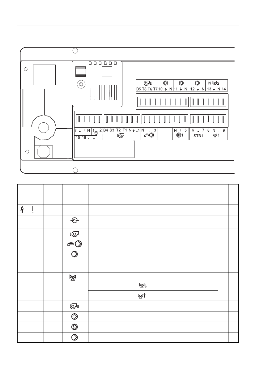
1.4 Allocation of the connectors 230 V parte . . . . . . . . . . . . . . . . . . . . . . . . . . . 6
1.4.1 Connection burner . . . . . . . . . . . . . . . . . . . . . . . . . . . . . . . . . . . . . . . 7
1.4.2 1-stage heat generator without burner norm-connector. . . . . . . . . . . 8
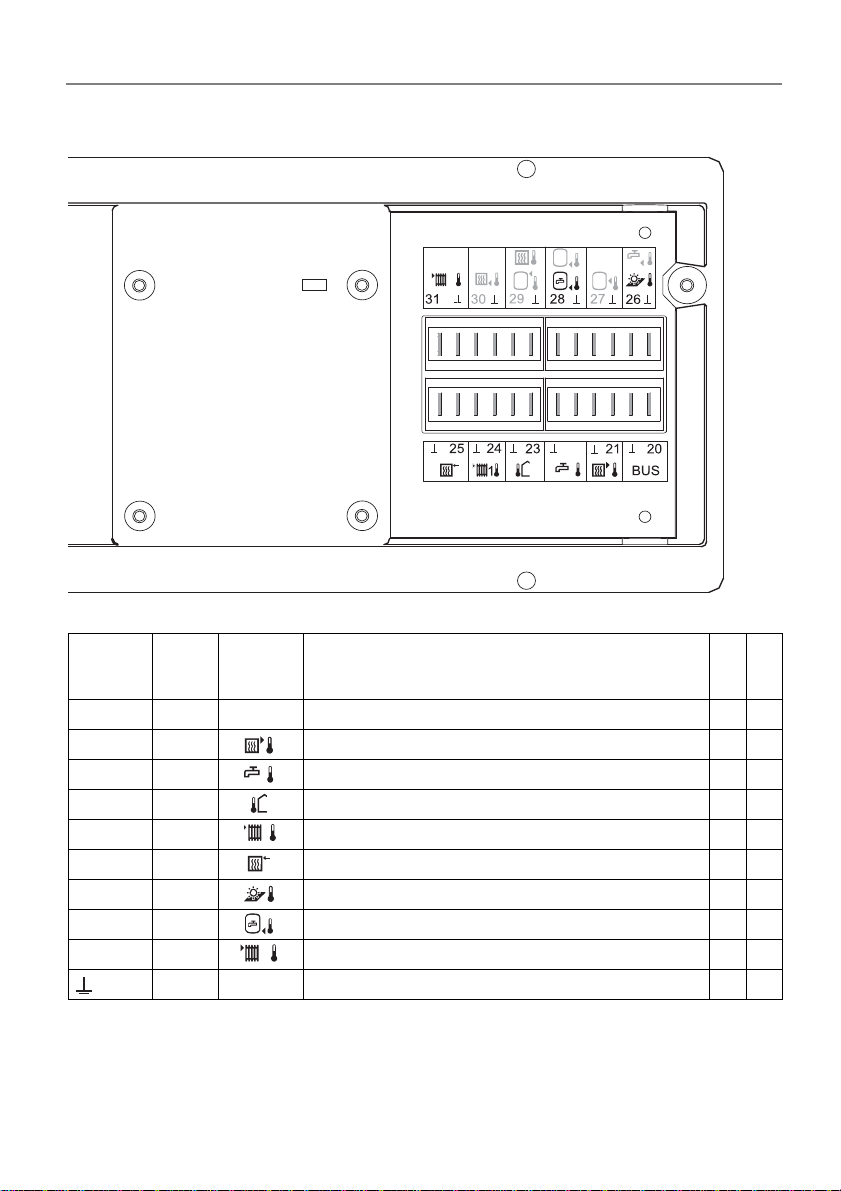
1.4.3 Allocation of the connectors sensors part . . . . . . . . . . . . . . . . . . . . . 9
1.5 Dimensions DKS - classic/ - expert . . . . . . . . . . . . . . . . . . . . . . . . . . . . . . 10
2 Specialist notes to the operation . . . . . . . . . . . . . . . . . . . . . . . . . . . . . . 11
2.1 Display check . . . . . . . . . . . . . . . . . . . . . . . . . . . . . . . . . . . . . . . . . . . . . . . 11
2.2 Structure of the parameter levels . . . . . . . . . . . . . . . . . . . . . . . . . . . . . . . . 12
3 Parameter levels. . . . . . . . . . . . . . . . . . . . . . . . . . . . . . . . . . . . . . . . . . . . 13
3.1 Level 1 and 2 . . . . . . . . . . . . . . . . . . . . . . . . . . . . . . . . . . . . . . . . . . . . . . . 13
3.2 Service level . . . . . . . . . . . . . . . . . . . . . . . . . . . . . . . . . . . . . . . . . . . . . . . 13
3.2.1 Operating data "dat". . . . . . . . . . . . . . . . . . . . . . . . . . . . . . . . . . . . . 13
3.2.2 Switching output function on and off . . . . . . . . . . . . . . . . . . . . . . . . 13
3.2.3 Displaying the controller output ports. . . . . . . . . . . . . . . . . . . . . . . . 15
3.2.4 Change of parameters on level 3 . . . . . . . . . . . . . . . . . . . . . . . . . . 16
3.3 Change of settings in the coded service levels 4 to 12 . . . . . . . . . . . . . . . 17
3.3.1 Example: Sensor configuration store (parameter 4-0) . . . . . . . . . . . 17
4 General description of functions and parameters . . . . . . . . . . . . . . . . 19
4.1 Level 3 - Heating circuits/Domestic hot water . . . . . . . . . . . . . . . . . . . . . . 19
4.1.1 Heating curve/base point (parameter 3-1) . . . . . . . . . . . . . . . . . . . . 19
4.1.2 Room-temperature compensation
(Reinforcement room influence, p-part) (parameter 3-7) . . . . . . . . . . . . . 22
4.2 4th level - Configuration of the plant. . . . . . . . . . . . . . . . . . . . . . . . . . . . . . 23
4.3 5th level - Domestic hot water production . . . . . . . . . . . . . . . . . . . . . . . . . 23
4.3.1 Basic function of domestic hot water production . . . . . . . . . . . . . . . 23
4.4 7th level - Heating circle function . . . . . . . . . . . . . . . . . . . . . . . . . . . . . . . . 24
4.4.1 Basic functions heating circle function . . . . . . . . . . . . . . . . . . . . . . . 24
4.4.2 Heating limits . . . . . . . . . . . . . . . . . . . . . . . . . . . . . . . . . . . . . . . . . . 25
4.5 8th level - Solar function. . . . . . . . . . . . . . . . . . . . . . . . . . . . . . . . . . . . . . . 27
4.5.1 Basic functions solar . . . . . . . . . . . . . . . . . . . . . . . . . . . . . . . . . . . . 27
4.6 10th-11th level - Boiler management . . . . . . . . . . . . . . . . . . . . . . . . . . . . . 27
4.6.1 Basic functions heat generator management. . . . . . . . . . . . . . . . . . 27

Operating manual
DKS - classic DKS - expert
Dok. Nr. 112819 31/2011 3
5 Overview of settings . . . . . . . . . . . . . . . . . . . . . . . . . . . . . . . . . . . . . . . . 28
5.1 3rd level . . . . . . . . . . . . . . . . . . . . . . . . . . . . . . . . . . . . . . . . . . . . . . . . . . . 28
5.2 4th level - Configuration of the plant. . . . . . . . . . . . . . . . . . . . . . . . . . . . . . 30
5.3 5th level - DHW production . . . . . . . . . . . . . . . . . . . . . . . . . . . . . . . . . . . . 31
5.4 7th level - Heating circuits . . . . . . . . . . . . . . . . . . . . . . . . . . . . . . . . . . . . . 31
5.5 8th level - Solar functions . . . . . . . . . . . . . . . . . . . . . . . . . . . . . . . . . . . . . 32
5.6 10th level - Parameters of heat generator . . . . . . . . . . . . . . . . . . . . . . . . . 32
5.7 11th level - Parameters of heat generator . . . . . . . . . . . . . . . . . . . . . . . . . 33
6 Assistance for start-up and elimination of errors. . . . . . . . . . . . . . . . . 33
6.1 Checking the controller. . . . . . . . . . . . . . . . . . . . . . . . . . . . . . . . . . . . . . . . 33
6.2 Factory settings / RESET . . . . . . . . . . . . . . . . . . . . . . . . . . . . . . . . . . . . . . 34
6.2.1 Delete operating data. . . . . . . . . . . . . . . . . . . . . . . . . . . . . . . . . . . . 34
6.2.2 Unlock during error message. . . . . . . . . . . . . . . . . . . . . . . . . . . . . . 35
6.2.3 Reload factory settings. . . . . . . . . . . . . . . . . . . . . . . . . . . . . . . . . . . 35
6.3 Error-messages . . . . . . . . . . . . . . . . . . . . . . . . . . . . . . . . . . . . . . . . . . . . . 35
6.4 Error message . . . . . . . . . . . . . . . . . . . . . . . . . . . . . . . . . . . . . . . . . . . . . . 36
6.5 Heating circulation pump functions . . . . . . . . . . . . . . . . . . . . . . . . . . . . . . 36
6.6 Remote control operation . . . . . . . . . . . . . . . . . . . . . . . . . . . . . . . . . . . . . . 36
6.7 FS 5601 remote control . . . . . . . . . . . . . . . . . . . . . . . . . . . . . . . . . . . . . . . 37
6.7.1 Connecting the FS 5601 remote control . . . . . . . . . . . . . . . . . . . . . 37
6.7.2 Start-up of the FS 5601 remote control . . . . . . . . . . . . . . . . . . . . . . 37
6.7.3 Operating with FS 5601 remote control . . . . . . . . . . . . . . . . . . . . . . 38
7 Technical data . . . . . . . . . . . . . . . . . . . . . . . . . . . . . . . . . . . . . . . . . . . . . 39
7.1 General data. . . . . . . . . . . . . . . . . . . . . . . . . . . . . . . . . . . . . . . . . . . . . . . . 39
7.2 Checking temperature sensors . . . . . . . . . . . . . . . . . . . . . . . . . . . . . . . . . 40
8 Hydraulic variants DKS - classic /- expert . . . . . . . . . . . . . . . . . . . . . . . 41
8.1 Variant 1: DKS - expert . . . . . . . . . . . . . . . . . . . . . . . . . . . . . . . . . . . . . . . 41
8.2 Variant 2: DKS - expert . . . . . . . . . . . . . . . . . . . . . . . . . . . . . . . . . . . . . . . 42
8.3 Variant 1: DKS - classic . . . . . . . . . . . . . . . . . . . . . . . . . . . . . . . . . . . . . . . 43
8.4 Variant 2: DKS - classic . . . . . . . . . . . . . . . . . . . . . . . . . . . . . . . . . . . . . . . 44
8.5 Variant 3: DKS - classic . . . . . . . . . . . . . . . . . . . . . . . . . . . . . . . . . . . . . . . 45
9 Explanation of terms and abbreviations . . . . . . . . . . . . . . . . . . . . . . . . 46
10 INDEX . . . . . . . . . . . . . . . . . . . . . . . . . . . . . . . . . . . . . . . . . . . . . . . . . . . . 47

Operating manual
DKS - classic DKS - expert
4Dok. Nr. 112819 31/2011
1 Information for mounting
1.1 General information
Electrical installation and safety must correspond to local regulations. The control-
ler is to left under continuing tension in order to guarantee functional readiness at
any time. Pre-positioned power switches are, therefore limited to emergency or
main switches which are usually left in the ’on position.
Warning: Make sure all electricity is switched off or fuses removed be-
fore beginning wiring work. The electricity supply must be switched
off before connecting or removing connectors. Never change the wi-
res and connections of the controller.
Connections of sensors, remote controllers, data BUS etc. to the controller must
be installed separately from those to the mains.
It may be advisable to suppress inductive loads (such as contactors, relays, mixer
drive units etc.) in the vicinity of the programmable thermostat by means of RC
circuits over their coils. (Recommended: 0.047 mF/100W, 250 VAC)
Unused sensor and signal inputs and outputs must not be connected.
The respective symbols and temperatures will not be displayed when
checking the sensors. The parameter 7-0 must be set on 3 for an unu-
sed heating circuit.
The data in this chapter refers to the connector numbering at the con-
troller. This connector numbering may deviate with installation in a
switchgear cabinet etc. Please refer to the appropriate documents.

Operating manual
DKS - classic DKS - expert
Dok. Nr. 112819 31/2011 5
1.2 Preparation of the assembly and start-up
The two fixing screws can be seen in the front housing.
1. Wire and attach all electrical connectors.
2. The controller must be inserted into the intended installation cut-out and fixed
by means of the 2 fixing screws.
Before start-up it must be ensured that all components are correctly attached.
When the plant is correctly installed and ready for use the following safety precau-
tions must be taken:
• check that the protective fuse of the electricity installation is in order
• check that all necessary connectors are joined
• check that all switches are switched on
• check that all necessary sensors are attached
• check that the output functions work correctly.
1.3 Start-up
The basic display (as example see the cover page) appears after switching on the
boiler. The parameters can be adjusted afterwards! If no basic display appears,
refer to "6.1 Checking the controller", page 33.
At start-up, determine that:
• the boiler is switched on
• the clock program is correctly programmed
• all temperatures are correctly adjusted
• heating is required according to the outside temperature
• the time and the date are set correctly.
Note: Due to the automatic summer/winter time change it is possible that the time
may be adjusted by 1 h. The time in each case will not change. The time is
corrected automatically, as soon as the controller is attached at the supply,
on the next day between 2.00 and 3.00 o'clock
In addition, depending upon plant configuration, carry out the following start-up
steps:
• Controller internal function check, see "6.1 Checking the controller",
page 33
• Examine the sensors, see "7.2 Checking temperature sensors", page 40
• If all sensors are attached correctly, the sensor configuration must be
saved (Parameter 4-0 = on)
• Switching output functions on and off, see user operating manual.

Operating manual
DKS - classic DKS - expert
6Dok. Nr. 112819 31/2011
1.4 Allocation of the connectors 230 V parte
Connec-
tor No. Abbr. Symbol Denomination
classic
expert
L N Net Net connection 230 VAC X X
1
2
SK Security circuit heat generator, potential-free (without
power)
X X
B4...L1 B1 Burner stage 1 X X
3 L Output phase DHW charge pump X X
5U1 Output phase heating circuit pump 1 green X X
6
7
STB1 STB1 Security thermostat heating pump circuit 1, green , poten-
tial-free (without power)
X X
8
9
M1 Output mixer heating circuit 1, green X X
8 = Mixer OPEN
9 = Mixer CLOSE
B5...T7 B2 Burner stage 2 X X
10 COutput phase DHW circulation pump X X
11 SOutput phase solar pump X X
12 U2 Output phase heating circuit pump 2 red X
1

Operating manual
DKS - classic DKS - expert
Dok. Nr. 112819 31/2011 7
1.4.1 Connection burner
13
14
M2 Output mixer heating circuit 2, red X
14 = Mixer OPEN
13 = Mixer CLOSE
15
16
Not Heating emergency switch, potential-free (without power) X X
PE Additional ground X X
Connec-
tor No. Abbr. Symbol Denomination
classic
expert
2
WireWire
A
Connector 3-pol
black
A
Connector 4-pol
brown
Ye/gr
Connector Cable
Ye/gr
Cable

Operating manual
DKS - classic DKS - expert
8Dok. Nr. 112819 31/2011
1.4.2 1-stage heat generator without burner norm-connector
• Unscrew and remove the cable with mating connector
• Use the screw connectors of the panel controller
Connection by the direct power supply of the heat generator
screw connectors of the panel controller
Power supply heat generator

Operating manual
DKS - classic DKS - expert
Dok. Nr. 112819 31/2011 9
1.4.3 Allocation of the connectors sensors part
Connec-
tor No. Abbr. Symbol Denomination
classic
expert
20 eBUS eBUS eBUS X X
21 TK Sensor heat generator X X
22 TB Sensor domestic hot water X X
23 TA Outside temperature sensor X X
24 TV1 Flow temperature sensor heating circuit 1, green X X
25 SW Setpoint value input analog 0-10V X X
26 TKO Solar panel sensor X X
28 TBU DHW tank bottom with solar application X X
31 TV2 Flow temperature sensor heating circuit 2, red X
MGround X X
22
2
1
2

Operating manual
DKS - classic DKS - expert
10 Dok. Nr. 112819 31/2011
1.5 Dimensions DKS - classic/ - expert
Fixing housing
290
265
405
116
128
4,4
4,4
8,5
8,5
A
A
A
A
98 11
Screw hole A
145
84,7
180
115
100
290
400
450

Operating manual
DKS - classic DKS - expert
Dok. Nr. 112819 31/2011 11
2 Specialist notes to the operation
2.1 Display check
When first switching on or after a RESET the display appears temporary the soft-
ware-version and all segments.
The controller changes afterwards to the normal indication.
Note: The display test takes place with closed or open cover.
1. Software number 521822
Note: First zeros in the second line are not indicated.
2. Software version 6.3
3. Display representation with all segments

Operating manual
DKS - classic DKS - expert
12 Dok. Nr. 112819 31/2011
2.2 Structure of the parameter levels
The parameter levels and parameters are divided into three entrance stages:
• uncoded: Level 1 to 3 (user and specialist)
• code 1: Level 4 to 19 (specialist)
• code 2: Level 4 to 11 (system supplier)
Note: In the levels 4 to 11 the individual parameters are assigned to code 1 or
code 2. Parameters in code 2 are indicated only after input the code.
You receive the code from your system supplier.
Parameter levels
uncoded
(specialist)
coded
(specialist = code 1;
system supplier = code 2)
...
Parameters ... ... ...

Operating manual
DKS - classic DKS - expert
Dok. Nr. 112819 31/2011 13
3 Parameter levels
3.1 Level 1 and 2
see the user operating manual doc. no. 112818.
3.2 Service level
In the service level a heating technician can make basic adjustments and queried
functions which give information about the correct mode of operation of the plant.
3.2.1 Operating data "dat"
Operating data can be queried, which is important for the plant operators and also
gives information about the interpretation and economy of the heating system, e.g.
the burner running times. More about this can be found in the user operating ma-
nual doc. no. 112818.
3.2.2 Switching output function on and off
This function serves the heating specialist for testing output functions. Each output
function may be selected and switched on or off for checking the components such
as pump, mixer etc. The system can be tested to check whether the switched-on
output function is correctly executed.
This function is not executable while operating in manual mode .
During the checking of the output functions the control and security
functions are not in use. The specialist must continuously check the
condition of the plant, before and during this phase.
The exceeding of critical values must be prevented manually.
Operation step Operation Display
Select the heating circuit
(in case of setting on 7-0)
Select service level
D
B
DKS expertDKS expert
D
A

Operating manual
DKS - classic DKS - expert
14 Dok. Nr. 112819 31/2011
Note: Depending upon controller version, relay symbols which are not available
also appear, see operating manual Doc. No. 112818, "Displaying the controller
output ports".
Select function "out"
Select output function
Example: A1 = burner stage I = "off"
Select output function
Example: A1 = burner stage I = "on"
Select further relays or leave function Close cover The standard display
appears
Operation step Operation Display
B
2 x
A
B

Operating manual
DKS - classic DKS - expert
Dok. Nr. 112819 31/2011 15
3.2.3 Displaying the controller output ports
Depending on the operating mode, some of these symbols will be shown.
Symbol Designation
heating circuit/generator (1=green; 2=red)
DHR - classic DHR - com-
fort
1
green
2
red
Generator I or burner stage I b1 A1 A1
Burner stage II b2 A12 A12
Heating circuit mixing valve open M+ A6 A6 A8
Heating circuit mixing valve closed M- A5 A5 A7
Heating circuit circulation pump UA4 A4 A9
Charging pump DHW LA2 A2
Circulation pump DHW CA11 A11
Solar pump SA10 A10

Operating manual
DKS - classic DKS - expert
16 Dok. Nr. 112819 31/2011
3.2.4 Change of parameters on level 3
Example: Room protection temperature (parameter 3-0)
Note: Control steps apply also to following parameters!
Note: All uncoded functions/parameters are described in the user opera-
ting manual (Doc. No. 112818) !
Operation step Operation Display
Select the heating circuit
(if switched ON, parameter 7-0)
Select service level
Select function
Parameter 3-0
Example: 10.0 °C
Parameter 3-0
change value, example: 12.0 °C
Select another function
or close the cover
The setting is stored
The standard display ap-
pears
D
B
DKS expertDKS expert
D
A
B
1 x
A
B

Operating manual
DKS - classic DKS - expert
Dok. Nr. 112819 31/2011 17
3.3 Change of settings in the coded service levels
4 to 11
3.3.1 Example: Sensor configuration store (parameter 4-0)
Note: Control expiration applies to all following adjusters!
Operation step Operation Display
Select the heating circuit
(if switchet ON, parameter 7-0)
Select service level
Set code
Confirm code
Select parameter level
Example: Level 4
Select parameter
Example: parameter 4-0
Change parameter
Example: on
D
B
DKS expertDKS expert
D
A
B
A
1 X
B
A
B

Operating manual
DKS - classic DKS - expert
18 Dok. Nr. 112819 31/2011
Select another function
or close the cover
The setting is stored
The selected function or
the standard display
appears
Operation step Operation Display

Operating manual
DKS - classic DKS - expert
Dok. Nr. 112819 31/2011 19
4 General description of functions and
parameters
4.1 Level 3 - Heating circuits/Domestic hot water
4.1.1 Heating curve/base point (parameter 3-1)
The heating curve indicates the relationship between the flow water and the out-
side temperature, ΔTV/ΔTA.
Because of the building's thermal inertia, it is recommended to per-
form no more than one adjustment step per day.
-15 -10 -5 0
5
10
15
20
25
5
15
25
35
45
55
65
75
85
°C
°C
TA
°C
15 °C
25 °C
Flow / boiler
set point maximum
0
0.4
0.8
1.2
1.6
2.0 2.4 3.0 4.0 5.0
Gen. flow temperature (TV)
Room temperature
Set point
Slope
Slope
Outside temperature
Base point

Operating manual
DKS - classic DKS - expert
20 Dok. Nr. 112819 31/2011
Adjusting the heating curve slope and base point
The heating curve is governed by the following adjustments:
The table below will assist in determining the heating curve appropriate to a given
heating system. You will need to know the type of heating system, and the climatic
zone in which it will operate.
High-temperature 90/70 Radiator heating
Medium-temperature 70/50 Radiator heating
Low-temperature 50/35 Underfloor heating
Ultra-low temperature 40/30 Underfloor heating
Example:
Heating system = 70/50 Climatic zone - 8 °C = E
Base point at TA 20 °C = 25 °C Resulting :=1.6
Function Symbol Basic setting performed by
Slope Specialist
(probably adjusting by user)
Base point flow temperature Specialist
Set point room temperature User
Set point reduced room tem-
perature
User
Heating
system
class
Base point:
TV at TA
+ 20 C
Slope of heating curve = ΔTV / ΔTA
40/30
50/35
70/50
90/70
22
23
24
19
20
21
24
25
26
25
26
30
31
30
35
0.5
0.6
0.7
0.8
0.9
1.0
1.1
1.2
1.3
1.4
1.5
1.6
1.7
1.8
1.9
2.0
2.1
2.2
2.3
2.4
2.5
2.6
2.7
2.8
2.9
3.0
3.2
3.4
AD H
BEG
CF I K
BE
AD I
CFGH K
CF
AE K
BD GHI
CDE
BAFG
HK
I
AHIK
BCDEFG
ABC DE F G H KI
KIHGFEDCB
A
Climatic zone where the building is located?
- 16 °C = A- 12 °C = C- 8 °C = E- 4 °C = G0 °C = I
- 14 °C = B- 10 °C = D- 6 °C = F- 2 °C = H+2 °C = K
Other manuals for DKS-classic
1
This manual suits for next models
2
Table of contents
Other OEG Boiler Supplies manuals
Popular Boiler Supplies manuals by other brands

Buderus
Buderus Logamax plus GB142-24 instructions

Grunbeck
Grunbeck GENO-Neutra FNH-420-R Operation manual

TriangleTube
TriangleTube PGRKIT30 Assembly instructions

Honeywell
Honeywell AQ25A Series Technical reference booklet

Immergas
Immergas 3.014083 quick start guide

LK
LK 816 ThermoKit E Eco instruction manual