Watts Vision BT-CT03 RF Quick start guide

wattswater.eu
EN
FR
DE
NL
IT
ES
DA
SV
NO
FI
Installation and user guide.................................................................................................................................. 2-24
Guide d‘installation et d‘utilisation..................................................................................................26-48
Installations- und Bedienungsanleitung.................................................................................50-72
Installatie- en gebruikersgids....................................................................................................................74-96
Guida all‘installazione e all‘uso......................................................................................................... 98-120
Guía de instalación y uso..........................................................................................................................122-144
Installations- og brugervejledning............................................................................................146-168
Installations och användaranvisningar.............................................................................170-192
Installasjons- og brukerhåndbok.................................................................................................194-216
Asennus- ja käyttöopas.................................................................................................................................218-240
BT-CT03 RF
Central Unit WIFI
Vision®Wireless
Installation and operational manual

EN
2BT-CT03-RF-IOM-FR-W-EN-10-23
TABLE OF CONTENT
General information .............................................................................................................................................................................................................3
1. Presentation
............................................................................................................................................................................................................................... 4
2. Installation............................................................................................................................................................................................................................................4
2.1 Installation sequence
2.2 Install your central
2.2.1 Wall mounting
2.2.2 Table installation (with optional mini USB cable – sold seperately)
2.3. Main screen icons description
2.3.1 General pictograms and actions
3. Settings........................................................................................................................................................................................................................................................ 7
3.1 Main menu
3.2 Adjust time / user settings
3.3 Configure your house
3.4 Pair your devices to the central
4. Hydraulic system assignement............................................................................................................................................ 11
5. Installation types (heating/cooling)........................................................................................................................... 12
6. Set up Wifi connection for remote control.......................................................................................... 15
7. Heating/cooling devices management & programming..................................16
7.1 Programming your devices
7.2 Lighting devices management
7.3 ON/OFF devices management
8. Voice control.............................................................................................................................................................................................................................21
8.1 Amazon Alexa
8.2 Google home
3.3 Google Home and Amazon Alexa controls
9. Maintenance............................................................................................................................................................................................................................. 22
10. Technical characteristics................................................................................................................................................................. 22
11. EU Declaration of conformity................................................................................................................................................. 23
12. Compatible devices .........................................................................................................................................................................................24
EN
3
BT-CT03-RF-IOM-FR-W-EN-10-23
GENERAL INFORMATION
Safety warnings and operating
instructions
• This product should be installed prefer-
ably by a qualified professional.Subject
to observation of the above terms, the
manufacturer shall assume the liabil-
ity for the equipment as provided by
legal stipulations. All instructions in this
Installation & Operation manual should
be observed when working with the
controller.
• Failures due to improper installation,
improper use or poor maintenance are
voiding manufacturer liability.
• Any attempt to repair voids the respon-
sibility and the obligation to guarantee
and replacement from the manufacturer.
• Risk of explosion if battery is replaced
by an incorrect type.
• This device may be used by children
aged at least 8 years and by people
with reduced physical, sensory or men-
tal capabilities or lack of experience or
knowledge, if they are properly super-
vised or if instructions relating to the
safe use of the device have been given
to them and if the risks involved have
been understood. Children should not
play with the device. Cleaning and user
maintenance must not be carried out
by children without supervision.
Disposal and recycling
information
The full text of the EU declaration of con-
formity is available at the following internet
address: www.wattswater.eu
• 2012/19/EU (WEEE directive): Products
marked with this symbol cannot be dis-
posed of as unsorted municipal waste
in the European Union. For proper recy-
cling, return this product to your local
supplier upon the purchase of equiva-
lent new equipment, or dispose of it at
designated collection points. For more
information see: www.recyclethis.info
• 2006/66/EC (battery directive): This
products contains a battery that cannot
be disposed of as unsorted municipal
waste in the European Union. See the
product documentation for specific bat-
tery information. The battery is marked
with this symbol, which may include
lettering to indicate cadmium (Cd), lead
(Pb), or mercury (Hg). For proper recy-
cling, return the battery to your supplier
or to a designated collection point. For
more information see: www.recycle-
this.info

EN
4BT-CT03-RF-IOM-FR-W-EN-10-23
1. PRESENTATION
Thank you for choosing Vision®Wireless,
a Wireless communication system for
controlling heating and cooling system.
It allows multi zones management (up to
50) of your electrical and hydraulic heating
system.
The central unit, main characteristics:
• Touch screen
• Interface via internet (WiFi)
• Wall mountable with power supply
85-265VAC (50-60) Hz
• Table mountable with supplied bracket
and mini USB power supply (0-5V)
(sold separately)
• Back up Battery for installation opera-
tion of 1 hour maximum
• RF Communication only with Vision®
Wireless devices (up to 40m internal,
extendable with repeater)
• Able to manage up to 50 zones or
rooms and 4 main supply circuits with
a dedicated pump or boiler on each
• Multiple heating / cooling devices control
• SD Card slot for updating software
• Intuitive menus for devices manage-
ment
Content of the packaging:
• Central unit
• 230V Flush mounted power supply
• wall/table support
• CE conformity declaration
• Quick installation guide
2. INSTALLATION
2.1 Installation sequence
Please follow the set-up sequence below;
STEP 1 Install your central unit (see 2.2
Install your central)
STEP 2 Create your house / create and
name your rooms (see 3.3 Configure your
house). Please note when pairing the WFC-
03 HC RF with the central unit, the rooms
are automaticaly created according to the
number of RF thermostats.
STEP 3 Pair your devices to the central
controller / allocate them to the appropriate
rooms (see 3.4 Pair your devices to the
central). Please charge the central unit
for at least 1 hour before pairing the
devices already mounted.
STEP 4 Personalise your central unit user
settings (see 3. Settings)
STEP 5 Set up Wifi for remote control of
your system via smartphone / tablet (see 6.
Set up Wifi control)
STEP 6 Program your devices so that they
work on a time schedule (see 7. Heating /
Cooling Device Management)

EN
5
BT-CT03-RF-IOM-FR-W-EN-10-23
2.2 Install your central
2.2.1 Wall mounting
2.2.2 Table installation (with
optional mini USB cable – sold
seperately)
Connect the central unit with the
mini USB cable (5V, 1A) and then
mount the leg support on it and
put the switch on ON position.
The central unit is ready for oper-
ation.
mains power supply
85-265vac - 50 /60hz
not to be used
Connect the power as described above
Screw the power unit on the wall and
connect to power supply.
Note! The tab must be on the top!
Put the switch on ON position
ON /OFF
Mount the Central on the
power unit and slide it on the
bottom to clip it. The Central
is ready for operation.
ON /OFF
Mini
USB
cable
Tab
UP
EN
6BT-CT03-RF-IOM-FR-W-EN-10-23
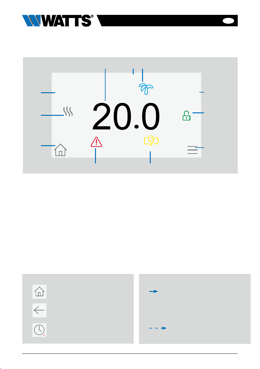
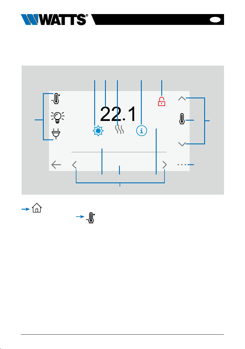
1Current time or room ambient
temperature. Make your choice by
pressing on it.
2Date
3Holidays mode status.
4 Display the ambient temperature in
desired room.
5Screen lock. Long press toggles
between locking / unlocking.
6Main menu.
7The device is working on battery
(! only for settings and pairing).
8Error flag – press to access RF, limits,
alarms, battery anomalies.
9Rooms access (if Central is locked –
cannot change settings).
10 Boiler status displayed if connected
to the Central.
11 Outside sensor temperature (Require
Outdoor sensor device)
2.3.1 General pictograms and actions
To return to the main screen.
To return to the previous screen.
The buttons with a red point
requires a long press (min 5s)
short press
long press (min 5s)
2.3 Main screen icons description
Tuesday 2023/08/29 08:24
19,0°C
Room 1
16,5°C
Outside
Battery powered
2 31
11
9
10 5
6
4
8 7
EN
7
BT-CT03-RF-IOM-FR-W-EN-10-23
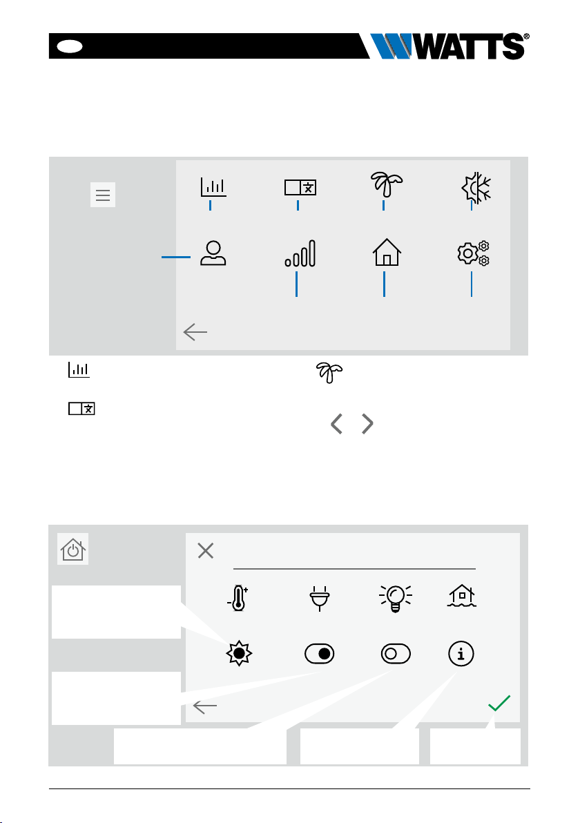
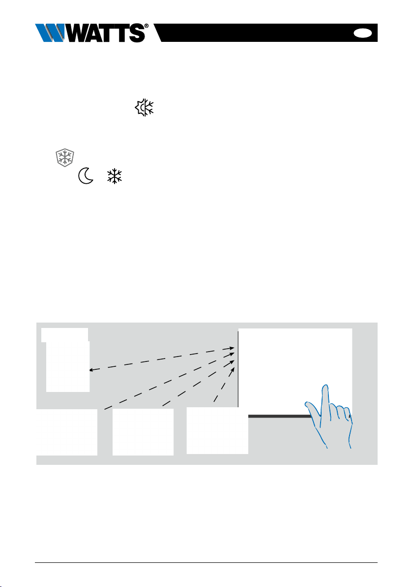
Whole installation
3 Holidays menu.
• To set the departure / return dates and
time.
• Use or to select year / month /
day / hour & minute.
Set and validate the operating mode
of the devices in holiday mode.
(Same menu then general commands
menu).
To select the heating/
cooling devices mode
for all the installation.
To select the ON/OFF
devices mode for all
the installation.
To select the lighting devices
mode for all the installation. To get information
about leak sensor To validate the
selections.
3. SETTINGS
3.1 Main menu
1Energy consumption statistics
menu.
2
ALanguage (the flag of the cur-
rent language is displayed). 8 lan-
guages are proposed. If you want to
select another language, you need to
insert the software (available on www.
wattswater.eu.) on a microSD then
select yours.
A
V.xx.xx
6 7 8
Press
to go to main menu 2 3 41
5

EN
8BT-CT03-RF-IOM-FR-W-EN-10-23
4 Heating/cooling mode man-
agement menu. See section
“Heating and cooling control”
5 User settings menu.
In this menu, you can set:
• Time, Date (Manual, Automatic).
• Time and date if the device is in manu-
al time update mode.
• Summer-Winter (Manual, Automatic).
• Temperature unit (°C, °F).
• Backlight brightness
• Screen saver (Enabled, Disabled).
• Factory default user (interface).
6 WIFI menu.
Reading button (refreshment).
The Internet access password allows to link
your central unit to your Internet account
(See below) for a remote control of your
system through the Internet or smartphone.
n.b.: At first use or software update, wait for
some time until the green State icon is active.
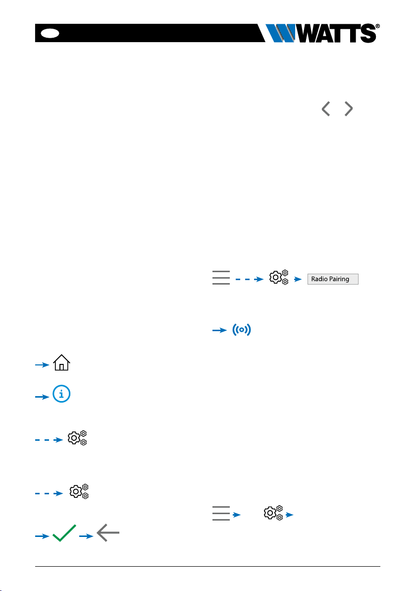
7 General commands menu. Use
this menu to put all the same devices
type in the same operating mode.
8 Installation menu
(Long press)
AWIFI settings
To set the Wi-Fi configuration (SSID
and password), you can do it manually
or by scanning active networks.
Configuration requesting a registration
on a web page is not supported.
Wi-Fi status:
0/2 : Central unit is not connected to
the Wi-Fi router
1/2 : Central unit is connected to the
Wi-Fi router but not to the server
2/2: Central unit connected to the
Wi-Fi router and to the server (pair-
ing of the central to an account is
required)
n.b.: The connection to Internet is rec-
ommended with Certified Wi-Fi routers
(http://www.wi-fi.org/certification).
n.b.: For the network scan, repeat
at least twice the operation if your
desired Wi-Fi network is not displayed.
If your desired Wi-Fi network is still
not displayed, enter the Wi-Fi settings
manually.
!
Installation
WIFI settings
House creation
Radio Pairing
Delete all devices
Anti freeze setpoint: 7.0°C
Heating Settings
H&C
General factory default
Update Firmware
Delete a device
A
D
J
B
E
C
F
G
H
I
EN
9
BT-CT03-RF-IOM-FR-W-EN-10-23
BHouse creation
See house creation section.
CRadio pairing
See radio pairing section.
DDelete a device
Select device type and then the
device.
EDelete all devices
All devices installed in the system will
be deleted (rooms will be maintained).
FAntifreeze setpoint
You can set the antifreeze setpoint as
reference for the whole installation.
GHeating setting
You can fix setpoint limitations (min/
max) per zone and the offset assigned
to devices working in floor sensor reg-
ulation.
HHeating/cooling settings
You can set the installation in heating
mode, in cooling mode or in manual
mode. If you set the device in manual
mode, the icon appears on the
main menu
IGeneral factory default
To reset the system with the factory val-
ues, but the software version will remain
the same.
JUpdate Firmware
To update the software, with the SD-card.
The system is qualified to work with
SD-cards less than or equal to 16GB.
Select to proceed (long press)
Please wait the end of the update
procedure (The Wifi icon should be
available for the Wifi central unit) before
removing the microSD from the cen-
tral unit. The SW and the procedure to
update the central unit is available on
www.wattswater.eu.
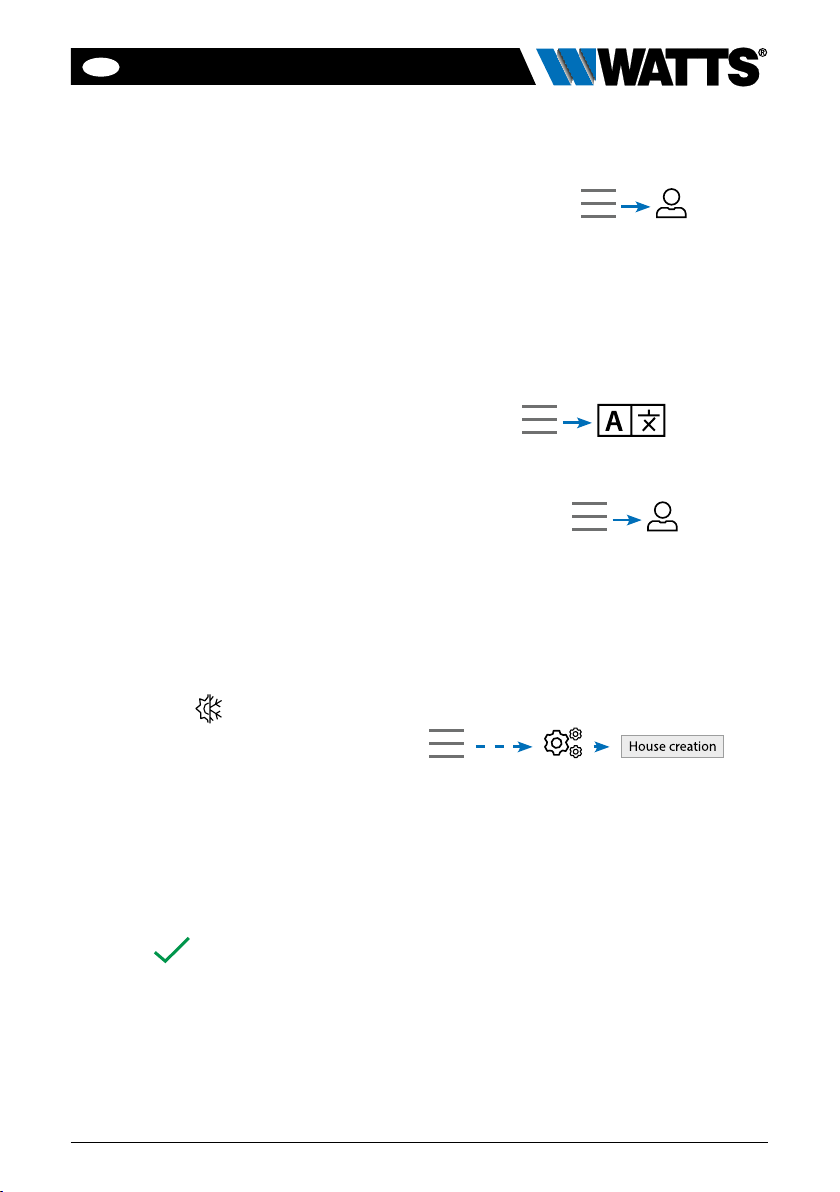
3.2 User settings
Adjust time/date
Date and time can be set manually or
automatically.
If auto is selected, location must be defined
on the smartphone or web application.
Then, the device will automatically get cur-
rent time from internet (Wi-Fi connection is
mandatory).
Language
Language settings - see MAIN MENU
section.
Personalization
Personalization settings (background color,
screen brightness, etc). See “User Settings
Menu” in MAIN MENU section for further
information.
3.3 Configure your house
Now, you need to “create” your house - a
list of rooms where various devices such
as thermostats will be placed.
Create all the rooms and re-name them
(e.g. Room 1 = Kitchen, Room 2 =
Lounge, etc)

EN
10 BT-CT03-RF-IOM-FR-W-EN-10-23
3.4 Pair your devices to the
central
• Install your devices (see relevant device
manuals)
• Create the room if it doesn’t exist (See
section 3)
• Go to Radio pairing
• Choose the device type (heating, On/Off
device, etc)
• Choose the room
• Note: The master (WFC-03 HC RF with
thermostat) must be paired first
• Put the device in pairing mode (refer to
the device manual)
• Start the pairing on the Central
• Follow the instructions given by the
Central (check on the device that the
pairing is successful, refer to the device
manual)
• n.b.: Automatic pairing time in case of
RF communication loss: 10s.
• n.b.: Pairing of the repeater: Select any
device type, any room and does not
consider the pairing failure message on
the central unit at the end of the proce-
dure. The led should be green fix on the
repeater.
• When you have finished pairing all devic-
es, please check that the range allows
good communication. To do this, adjust
the setpoint temperature on the central
and make sure that the information is
received by the thermostat/receiver.
• Check the successful installation
In the radio pairing menu, choose test RF
installation.
You will have warning in home
menu for RF errors communications. The
warning flag should appear for a maximum
of 10mn. It would then disappear if there
are no communication problems. If not,
check devices showing RF errors, try
moving them to another place and repeat
the procedure.
Room 1
Scroll over rooms. To change current room (zone) name.
To create or
add a room
(zone).
To delete a
room (zone).
Current room name
EN
11
BT-CT03-RF-IOM-FR-W-EN-10-23
4. HYDRAULIC SYSTEM
ASSIGNEMENT
If your installation has several separate
hydraulic circuits containing their own
pumps or boilers, you may want to drive
each pump/boiler separately from specific
heating receivers or thermostatic actua-
tor(s). With Vision® Wireless you can cre-
ate and control up to 4 hydraulic circuits.
Each of the circuits will have an RF remote
circuit receiver linked to it that will activate
the intended pump and boiler. If at least
one heating receiver or thermostatic actu-
ator on the circuit has a demand, the linked
circuit receiver will operate and activate the
pump (and / or boiler).
STEP 1:Definewhichdeviceisassigned
to a hydraulic circuit
With the plan of your installation, define
which devices are on “circuit 1”.
Then, pair and configure all these devices
on circuit 1.
, enter a zone (room) that belong
to circuit 1,
, and select one device of circuit 1
(radio connecting box, radio receiver or radia-
tor thermostatic head)
Now you have entered the
configuration menu of the device. Select
the menu “Heating settings” and make
sure that “Hydraulic heating” is selected
You can now select the
hydraulic circuit linked to this receiver (e.g.
circuit 1).
Repeat the procedure for each device of
the room (zone) you want to link to the
hydraulic circuit. Further devices can be
selected using the buttons or at the
top of the device name.
Repeat the procedure for each room (zone)
that you want to link to hydraulic circuit
1. If you have assigned all rooms / devic-
es, repeat the procedure for any further
hydraulic circuits.
STEP 2:pairing radio receiver hydraulic
circuit with the central unit
For each circuit, you can link a circuit receiver
to drive the pump devices, valve drive or
heat / cool generator of the circuit. This can
be done for example by BT-WR02 RF.
Select “Circuit”, then select the number
of the circuit, e.g. circuit 1. Put the radio
receiver in pairing mode (BT-WR02 RF).
Repeat the procedure for additional
hydraulic circuits.
Heat and Cool installations
If your installation includes both heating and
cooling functions, you can switch either
from Heat to Cool manually or automati-
cally:
• If you have a WFC-03 HCM RF in your
installation set as “Master” (refer to
Manual instruction of the device) then
all is automatic you don’t have to do
anything
• For all other cases, you have to do the
switch manually:
then go in “H&C”.
There you will have the choice between
“Heating Only”, “Cooling Only” or “Manual
Reversible”.
EN
12 BT-CT03-RF-IOM-FR-W-EN-10-23
With this last option, you create a shortcut
in the main menu where you can easily
change Heat/Cool mode
Notes:
• In Cooling Mode, Reduced mode and
Antifreeze mode are inactive:
icon is displayed
instead of or
• In the thermostat, user can configure
the parameter “Cold” that allows the
zone to do Cooling or not. If it is set
to “No”, then if the mode of the zone
is Cooling then the zone won’t make
Cooling.
5. INSTALLATION TYPES (HEATING/COOLING)
TYPE 1 In this configuration:
• Pair first the thermostat (master - configured as a heating device) with the Central
before pairing the other devices (configured as heating devices).
• The thermostatic heads regulate on thermostat temperature.
ROOM 1
Master-Thermostat
and/or and/or
Thermostatic heads

EN
13
BT-CT03-RF-IOM-FR-W-EN-10-23
TYPE 2 In this configuration:
• Pair first the thermostat (master - configured as a heating device) with the Central
before pairing the other devices.
• The other devices regulate on thermostat temperature.
Warning! In this installation type, the thermostat (MASTER) must be in regulation Air
mode (not floor or Air + Floor).
TYPE 3 In this configuration (no thermostat):
• BT-TH configured as heating device. BT-PR, BT-FR, BT-WR can be configured as
an On / Off or lighting devices.
ROOM 1
and/or and/or and/or
ROOM 1
and/or and/or and/or
BT-PR03BT-TH BT-FR BT-WR
Master-Thermostat

EN
14 BT-CT03-RF-IOM-FR-W-EN-10-23
TYPE 4 In this configuration:
• Each thermostat is first paired with the appropriate WFC-03 HC RF and then the
WFC-03 HC RF are paired with the Central
• During the pairing, the Central automatically creates rooms according to the number
of thermostats (rooms) of master controller.
ROOM 1 ROOM 2 ..... ROOM 12
WFC-03 HC RF

EN
15
BT-CT03-RF-IOM-FR-W-EN-10-23
STEP 3 Create an Account
• Enter your details and select language.
• Select “Validate” (email will be sent to
you with link).
• Go to your email and click on the link.
• Go back to your App account and follow
the on screen instructions.
• Request a pairing code to link your
central unit. The pairing code (valid
24h) is sent to your email inbox.
In the WiFi status menu of the central
unit, enter the pairing code (internet access
password).
Your central unit should appear after a few
minutes in the application or the web page.
Click the refresh button if necessary. WiFi
status should read 2/2.
Please note! It may take up to a few hours
to display all rooms and devices in the
application. You can then operate your
central unit from anywhere.
Watts is not responsible for the correct
operation of the connected devices, and
potential damage caused by malfunction
or improper use of the connected devices
and appliances.
6. SET UP WIFI CONNECTION
FOR MOBIL APP REMOTE
CONTROL
STEP 1 Connect the central unit to
your WiFi network:
• Choose WiFi settings
• Choose Research Networks (searches
for your WiFi)
• Choose your WiFi from the list and
enter your regular WiFi password
• Observe unit counting down from 120
to zero
• Make sure that the central is now con-
nected to the WiFi network with an IP
address (WiFi status should read 1/2)
If after several attempts, connection is
unsuccessful, connect the central unit to
WiFi manually.
STEP 2 Download the app to your
device:
• For PC: click on this link or copy/paste
this URL on you Web browser
http://smarthome.wattselectronics.com/
mobile/dist/#/login
• For Smartphone: download WATTS
Vision®application from App store or
Google Play.
EN
16 BT-CT03-RF-IOM-FR-W-EN-10-23
1Device type choice (heating/cooling,
lighting, On/Off). These buttons are
only displayed if one device type is
installed in the room (colored if active).
2Current mode, press on this icon
to enter in the menu where you can
change the current operating mode.
3Ambient temperature or setting tem-
perature (setpoint) or humidity after
one press on 8.
4Heating/cooling indicator (animated if
demand).
5Information about the heating/cooling
devices installed in the room
6Only displayed if the screen is locked.
7Set the current setpoint (deactivated if
the screen is locked).
8To display either the ambient or setting
temperature or Humidity in 3.
9Quick access to the desired room.
10 Pilot wire status.
11 Current room name.
12 Floor temperature if floor regulation.
13 Room changing.
in the main screen and after
selecting the room
7. HEATING/COOLING DEVICES MANAGEMENT
& PROGRAMMING
-1°C
Ambient
Room 1
PW
Floor tem. : 30°C
34 5 62
17
8
9
13
11 1012

EN
17
BT-CT03-RF-IOM-FR-W-EN-10-23
Anti freeze Mode: Use this mode
to put your room in anti-freeze mode (the
temperature is set in the Installation menu)
OFF Mode: To switch OFF the
device (room in off mode). Be careful! In
this mode, your installation can freeze!
to access this modes menu:
Comfort Mode: Set the room
in comfort mode. If it remains active, the
comfort temperature will be followed all
the time.
Reduced Mode: Set the room
in reduced mode. If it remains active, the
reduced temperature will be followed all
the time.
Timer or Boost Mode: Temporary
derogation. Set the timer duration (days,
hours, minutes) by pressing on button,
then validate and set the desired tempera-
ture on main screen.
Comfort Auto Reduced Timer Ant.Free. OFF
Room 1
19.0°C15.5°C7.0°C
MODES
Comfort mode
Automatic mode Reduced mode Timer or Boost Mode
Anti-Freeze mode
OFF mode
EN
18 BT-CT03-RF-IOM-FR-W-EN-10-23
!
Room 1
Select
Create
Edit
Delete all devices
Anti freeze setpoint: 7.0°C
Heating Settings
H&C
General factory default
Update Firmware
Delete a device D
E
F
G
H
I
J
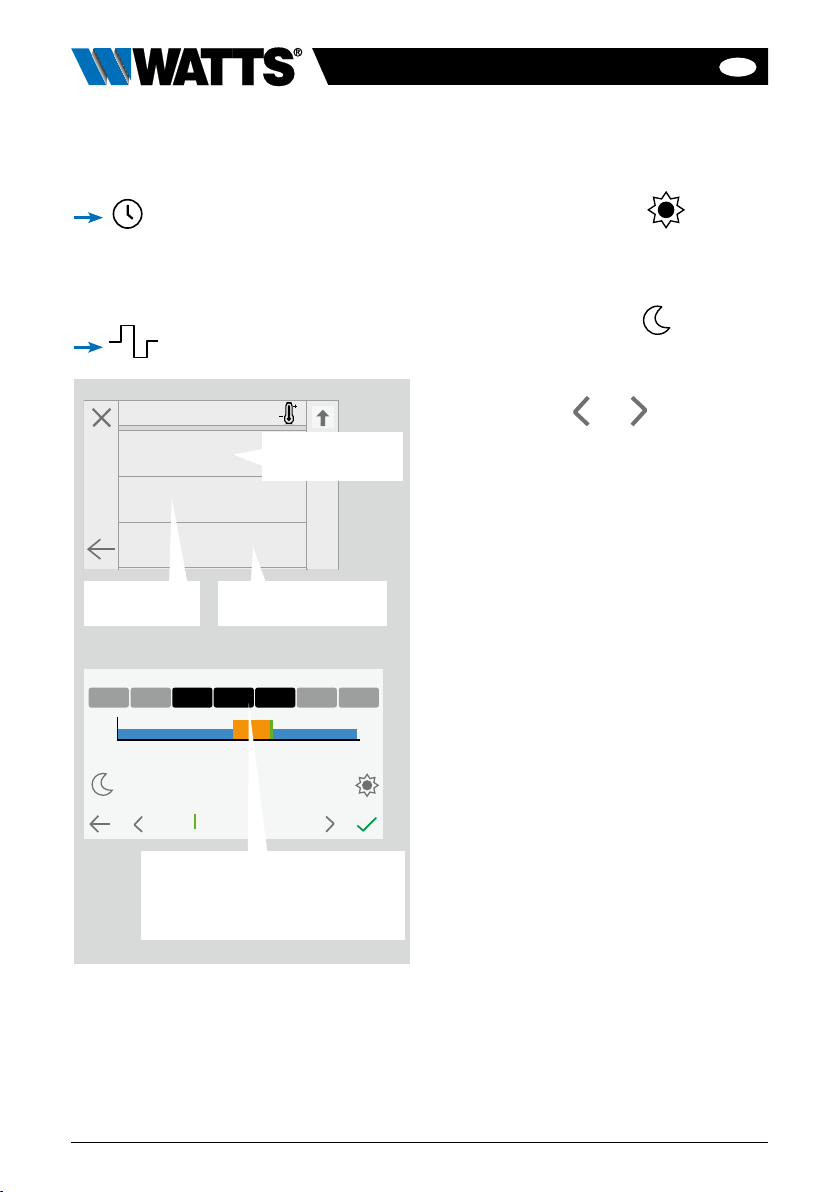
Program : Room 1
15:15
-> 15:30
15.5°C
0 6
12 18 24
19.0°C
Mon Tues Sat SunWed Thu Fri
7.1 Programming your devices
Auto Mode: In this mode, the
room temperature will follow the program
you have chosen. You can choose between
existing programs or you can create a new
one that you can modify as you want.
to select between :
Use the Comfort button to select
the hourly ranges during which the com-
fort temperature will be followed (orange
range)
• and the reduced button to select
the hourly ranges during which the
reduced temperature will be followed
(blue range).
• Use the arrows and to put the
cursor on the desired hours.
Validate the program; the validated days
are then highlighted in green (on this exam-
ple: Wednesday, Thursday and Friday).
The days that are not programmed are
displayed in grey.
• Information to view the current program
• Default programs:
P1: morning, evening & weekend.
P2: morning, midday, evening & weekend.
P3: day & weekend.
P4: evening & weekend.
P5: morning, evening (bathroom).
To select an
existing program
To create a
new program To view and modify
an existing program
Select the days for which you
want the same program (in the
example, Wednesday, Thursday
and Friday)

EN
19
BT-CT03-RF-IOM-FR-W-EN-10-23
7.2 Lighting devices
management
in the main screen and
1Device type choice (heating / cooling,
lighting, On / Off). These buttons are
only displayed if one device type is
installed in the room (colored if active).
2Information about the lighting devices
installed in the room.
3Indicates both the current lighting
device number / the number of lighting
devices in the room.
4Only displayed if the number of devices
is upper than 1; used to select the
devices in the room.
5Only displayed if the screen is locked.
6General management for all lighting in
the room.
7Quick access to the desired room.
8Current room.
9Room changing.
10 Indicates the lighting status. A press on
it switches the lighting status.
Please note that the lighting functionality
does not support programs. If you want
to program the lighting devices, please set
the devices as ON / OFF.
Room 2
Lighting
1/2
Whole room
3 44 52
1
10
6
7
9
8

EN
20 BT-CT03-RF-IOM-FR-W-EN-10-23
7.3 ON/OFF devices
management
in the main screen and on
1Long press to switch between auto
mode and normal mode (colored if
active).
2Information about the device.
3Indicates both the number of the current
device / number of devices in the room.
4Displayed only if the device is in Auto
mode, press to access and edit the
device program.
5Only displayed if the number of devices
is upper than 1; used to select the devic-
es in the room.
6Only displayed if the screen is locked.
7General management for all the
ON / OFF devices in the room.
8Quick access to the desired room.
9Current room.
10 Room changing.
11 Indicates the ON / OFF status. A press
on it switches the status of the device.
12 Device type choice (heating/cooling,
lighting, On / Off). These buttons are
only displayed if one device type is
installed in the room (colored if active).
Room 3
ON/OFF Device
1/3
Whole room
3 55 641 2
12
11
7
8
10
9
Other manuals for Vision BT-CT03 RF
1
Table of contents
Languages:
Popular Conference System manuals by other brands


Bosch
Bosch CCS 900 Ultro Installation and operating manual

Bell System
Bell System Com Key 416 Identification, Installation, Connection, Operation, and Maintenance Customer Equipment

Vidyo
Vidyo VidyoRoom HD-110 Getting started

EMC-PARTNER
EMC-PARTNER CN16 user manual

Intracom
Intracom WiBAS OSDR Commissioning manual

Twiins
Twiins D1 VA instruction manual